Transmission
Manual gearbox: Removal - Refitting
In this manual: Transmission
~10min read
F4R or F9Q
Essential special tools |
|
| Rou. 604-01 | Hub holder |
| Tav. 476 | Ball joint extractor |
| Mot. 1453 | Multi-adjustable engine mounting bracket, with retaining straps |
Essential equipment |
| steering wheel lock |
| component spring compressor |
Tightening torques |
|
| wheel mounting bolts | 11 daN.m |
| driveshaft nut | 28 daN.m |
| lower ball joint nut | 6.2 daN.m |
| steering ball joint nut | 3.7 daN.m |
| stabilizer bar ball joint nut | 4.4 daN.m |
| side cheek mounting bolts | 2.1 daN.m |
| gearbox bellhousing and starter bolts | 4.4 daN.m |
| engine torque rod bolt | 18 daN.m |
| subframe torque rod bolt | 10.5 daN.m |
| gearbox pendulum mount bolt | 6.2 daN.m |
| pendulum mount nut on bump stop | 18 daN.m |
| steering clevis bolt | 2.1 daN.m |
| front radiator crossmember mounting bolts | 10.5 daN.m |
| rear radiator crossmember mounting bolt | 2.1 daN.m |
| subframe crossmember mounting bolt | 6.2 daN.m |
| rear subframe mounting bolt | 14 daN.m |
| subframe brace mounting bolts | 10.5 daN.m |
| gearbox drain plug | 2.5 daN.m |
| gearbox filler plug | 0.3 daN.m |
| battery cover | 0.4 daN.m |

To avoid any risk of damaging the clockspring, observe the following instructions:
- Be sure to immobilise the steering wheel, wheels straight, using the steering wheel lock for the entire duration of the operation, before disconnecting the steering column and the rack.
- Any doubt about the correct centring of the clockspring requires removing the steering wheel to apply the centring method described in the Controls - Signalling chapter.
In this case, only qualified personnel who have received training must carry out the work.
REMOVAL
- Position the vehicle on a two-post lift.
- Remove the battery cover.
- Disconnect the battery, starting with the negative terminal.
- Remove the undershield.
- Drain the gearbox oil.
- Remove:
- the front wheels,
- the engine covers,
- the battery,
- the battery tray,
- the injection ECU with its bracket,
- the air flow meter,
- the air intake hose.
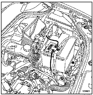
- Remove the wiring harness mountings.
- Unclip the gear selector cables from the gearbox.
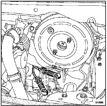
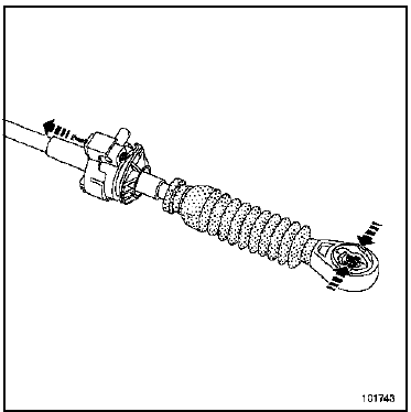
Note: Do not touch the spool valve.
F9Q
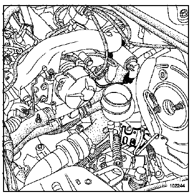
Disconnect the air duct between the intercooler and the turbocharger.
- Disconnect:
- the wheel anti-lock sensor wiring,
- the xenon headlamp levelling sensor wiring (if fitted).
- Remove the mudguards.
I - LEFT-HAND SIDE OF THE VEHICLE
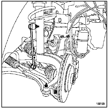
- Remove:
- the hub nut, using tool (Rou. 604-01),
- the steering track rod end, using tool (Tav. 476),
- the anti-roll bar link ball joint,
- the lower ball joint.
- Release the hub carrier from the driveshaft.
- Remove the driveshaft.
II - RIGHT-HAND SIDE OF THE VEHICLE
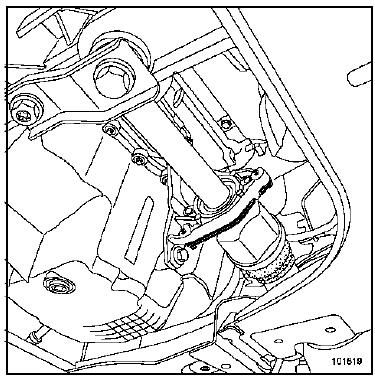
- Remove:
- the hub nut, using tool (Rou. 604-01),
- the steering track rod end, using tool (Tav. 476),
- the anti-roll bar link ball joint,
- the lower ball joint,
- the intermediate bearing bracket.
- Release the hub carrier from the driveshaft.
- Remove the driveshaft.
- Tie all the cooling radiators to the upper cross member using ropes.
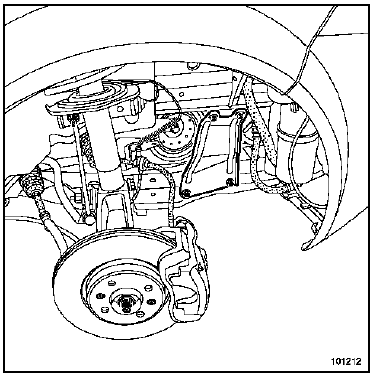
- Remove the side reinforcements.
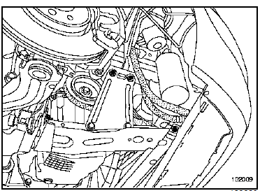
- Remove the radiator cross member.
- Remove:
- the catalytic converter bracket on the clutch housing,
- the starter motor mounting bolts,
- the starter motor.
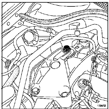
- Remove the upper torque strut.
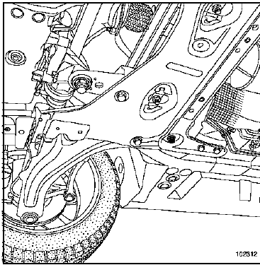
- Remove the lower torque strut.
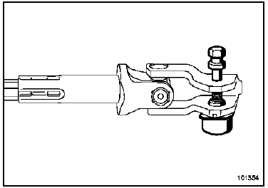
- Remove the steering yoke.
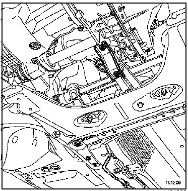
- Remove the subframe bracket.
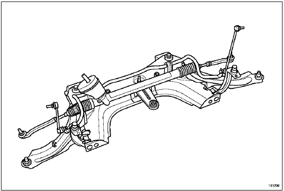
- Remove the subframe.
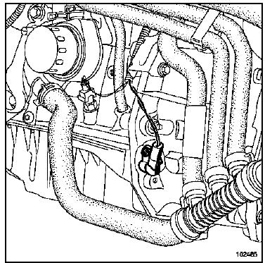
- Disconnect:
- the reverse gear connector,
- the top dead centre sensor.
- Drain the brake fluid reservoir using a syringe down to the clutch slave cylinder hose connection.
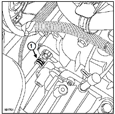
- Disconnect the clutch release bearing by removing the clip (1).
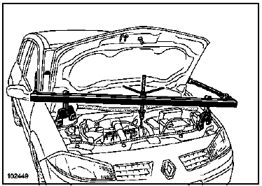
- Fit the engine support tool (Mot. 1453).
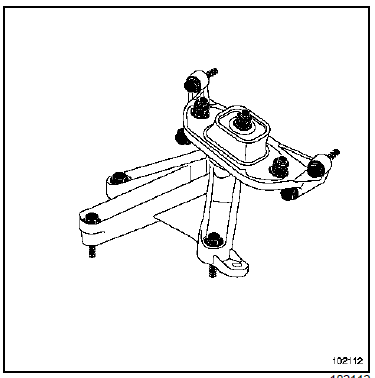
- Remove:
- the gearbox support bush,
- the gearbox pendulum mount,
- the upper gearbox torque bolts.
- Fit the unit support jack under the gearbox.
- Remove:
- the lower gearbox torque bolts,
- the gearbox mounting studs,
- the gearbox.
INSTALLATION
WARNINGDo not grease:
- the gearbox output shaft with grease, to avoid damaging the clutch release bearing,
- the clutch shaft splines.
- Make sure the engine - gearbox centring dowels are present and correctly positioned.
- Refit in the reverse order of removal.
- Tighten to the following torques:
- wheel mounting bolts (11 daN.m),
- the driveshaft nut (28 daN.m),
- the lower ball joint nut (6.2 daN.m),
- the steering ball joint nut (3.7 daN.m),
- stabilizer bar ball joint nut (4.4 daN.m),
- the side plate mounting bolts (2.1 daN.m),
- the gearbox and starter motor torque bolts (4.4 daN.m),
- the torque strut bolts on the engine (18 daN.m),
- the torque strut bolts on the subframe (10.5 daN.m),
- the gearbox pendulum mount bolts (6.2 daN.m),
- the pendulum mount nut on the bush (18 daN.m),
- the steering yoke fixing bolt (2.1 daN.m),
- front radiator crossmember mounting bolts (10.5 daN.m),
- the rear radiator cross member mounting bolts (2.1 daN.m),
- the subframe cross member mounting bolts (6.2 daN.m),
- the rear subframe mounting bolts (14 daN.m),
- the subframe tie rod mounting bolts (10.5 daN.m),
- the gearbox drain plug (2.5 daN.m),
- the gearbox filler plug (0.3 daN.m).
- Check the gearbox oil level.
The hydraulic clutch circuit must be bled, following these instructions:
- Add brake fluid to the reservoir.
- Bleed the circuit (see Mechanical Controls chapter).
- Top up the brake fluid level.
Connect the battery; carry out the necessary relearn procedures (see Battery chapter).
- Torque the battery cover (0.4 daN.m).
K4J or K4M or K9K
Essential special tools |
|
| Rou. 604-01 | Hub holder |
| Tav. 476 | Ball joint extractor |
| Mot. 1453 | Multi-adjustable engine mounting bracket, with retaining straps |
Essential equipment |
| component spring compressor |
Tightening torques |
|
| wheel mounting bolts | 11 daN.m |
| driveshaft nut | 28 daN.m |
| lower ball joint nut | 6.2 daN.m |
| steering ball joint nut | 3.7 daN.m |
| anti-roll bar link ball joint nut | 4.4 daN.m |
| side cheek mounting bolts | 2.1 daN.m |
| gearbox bellhousing and starter bolts | 4.4 daN.m |
| engine torque rod bolt | 10.5 daN.m |
| subframe torque rod bolt | 10.5 daN.m |
| gearbox pendulum mount bolt | 6.2 daN.m |
| pendulum mount nut on bump stop | 18 daN.m |
| front radiator crossmember mounting bolts | 10.5 daN.m |
| gearbox drain plug | 2.5 daN.m |
| gearbox filler plug | 0.3 daN.m |
| battery cover | 0.4 daN.m |

REMOVAL
- Position the vehicle on a two-post lift.
- Remove the battery cover.
- Disconnect the battery, starting with the negative terminal.
- Remove the undershield.
- Drain the gearbox oil.
- Remove:
- the front wheels,
- the engine covers,
- the battery,
- the battery tray,
- the injection ECU with its bracket,
- the air flow meter,
- the air intake hose.
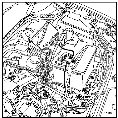
- Remove the wiring harness mountings.
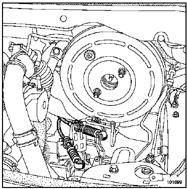
- Unclip the gear selector cables from the gearbox
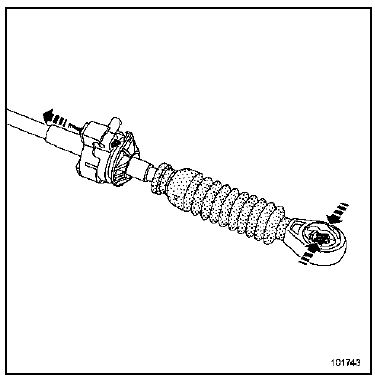
- Disconnect:
- the wheel anti-lock sensor wiring,
- the xenon headlamp levelling sensor wiring (if fitted).
- Remove the mudguards.
I - LEFT-HAND SIDE OF THE VEHICLE
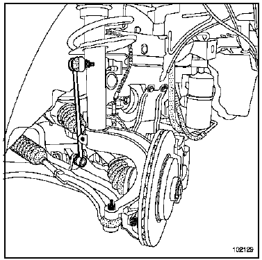
- Remove:
- the hub nut, using tool (Rou. 604-01),
- the steering track rod end, using tool (Tav. 476),
- the anti-roll bar link ball joint,
- the lower ball joint.
- Release the hub carrier from the driveshaft.
- Remove the left-hand driveshaft.
II - RIGHT-HAND SIDE OF THE VEHICLE
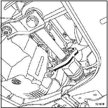
- Remove:
- the hub nut, using tool (Rou. 604-01);,
- the steering track rod end, using tool (Tav. 476),
- the anti-roll bar link ball joint,
- the lower ball joint,
- the intermediate bearing bracket.
- Release the hub carrier from the driveshaft.
- Remove the right-hand driveshaft.
- Tie all the cooling radiators to the upper cross member using ropes.
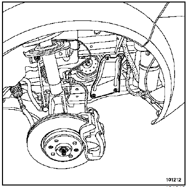
- Remove the side reinforcements.
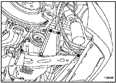
- Remove the radiator cross member.
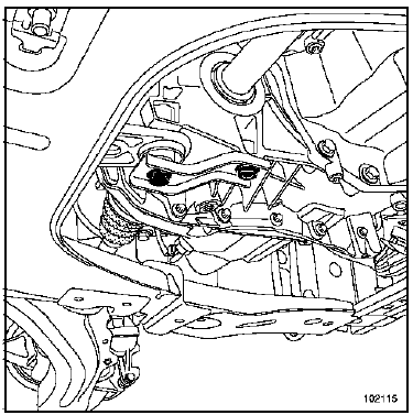
- Remove:
- the catalytic converter bracket on the clutch housing,
- the starter motor mounting bolts,
- the starter motor.
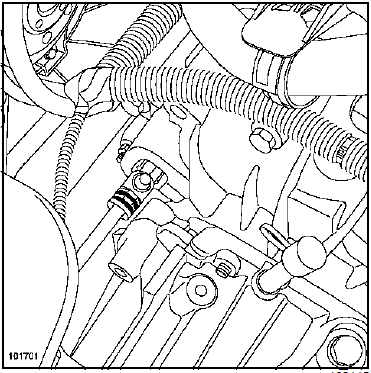
- Remove the torque strut.
- Disconnect:
- the reverse gear connector,
- the top dead centre sensor.
- Drain the brake fluid reservoir using a syringe down to the clutch slave cylinder hose connection
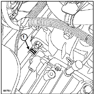
- Disconnect the clutch release bearing by removing the clip (1).
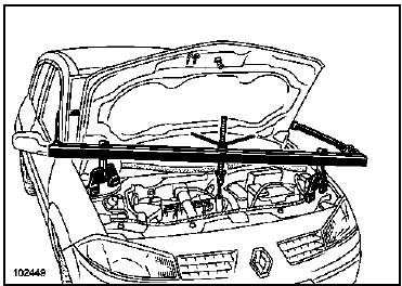
- Fit the engine support tool (Mot. 1453).
- Remove:
- the gearbox support bush,
- the upper gearbox torque bolts.
- Fit the unit support jack under the gearbox.
- Remove:
- the lower gearbox torque bolts,
- the gearbox mounting studs,
- the gearbox.
INSTALLATION
WARNINGDo not grease:
- the gearbox output shaft with grease, to avoid damaging the clutch release bearing,
- the clutch shaft splines.
- Make sure the engine - gearbox centring dowels are present and correctly positioned.
- Refit in the reverse order of removal.
- Tighten to the following torques:
- wheel mounting bolts (11 daN.m),
- the driveshaft nut (28 daN.m),
- the lower ball joint nut (6.2 daN.m),
- the steering ball joint nut (3.7 daN.m),
- the anti-roll bar link ball joint nut (4.4 daN.m),
- the side plate mounting bolts (2.1 daN.m),
- the gearbox and starter motor torque bolts (4.4 daN.m),
- the torque strut bolts on the engine (10.5 daN.m),
- the torque strut bolts on the subframe (10.5 daN.m),
- the gearbox pendulum mount bolts (6.2 daN.m),
- the pendulum mount nut on the bush (18 daN.m),
- front radiator crossmember mounting bolts (10.5 daN.m),
- the gearbox drain plug (2.5 daN.m),
- the gearbox filler plug (0.3 daN.m).
Check the gearbox oil level.
WARNINGThe hydraulic clutch circuit must be bled, following these instructions:
- Add brake fluid to the reservoir.
- Bleed the hydraulic circuit (see Mechanical Controls chapter).
- Top up the brake fluid level.
Connect the battery; carry out the necessary relearn procedures (see Battery chapter).
- Torque the battery cover (0.4 daN.m).
Test yourself
A quick Renault Megane quiz: every answer comes with an explanation and a link to the manual page.
Was this page helpful?