Timing belt
K4J or K4M
Essential special tools |
|
| Mot. 1453 | Multi-adjustable engine mounting bracket, with retaining straps |
| Mot. 1453-01 | Additional crank nut for engine lifting support Mot. 1453 |
| Mot. 1489 | TDC timing pin |
| Mot. 1368 | Eccentric tensioner pulley bolt tightening tool. Torx 8 key and 12.7 square drive |
| Mot. 1496 | Camshaft timing tool |
| Mot. 1490-01 | Camshaft pulley locking tool |
| Mot. 799-01 | Timing belt sprocket locking tool |
| Mot. 1487 | Camshaft cover refitting tool |
| Mot. 1488 | Camshaft covers refitting tool |
Tightening torques |
|
| crankshaft auxiliary pulley bolt | 4 daN.m + 115 +/- 15 |
| tensioner pulley fixing nut | 2.7 daN.m |
| idler pulley fixing bolt | 4.5 daN.m |
| new camshaft pulley nuts | 3 daN.m + 84 +/-4 |
| camshaft pulley bolt of the phaser | 7.5 daN.m |
| phaser pulley plug | 1.5 daN.m |

CAUTION Never turn the engine in the reverse direction to normal operation.
REMOVAL
- Position the vehicle on a two-post lift.
- Disconnect the battery (see Electrical Equipment chapter).
- Remove:
- the engine undershield,
- the drive belt (Chapter Upper and front engine, Drive belt, page 11A-1).
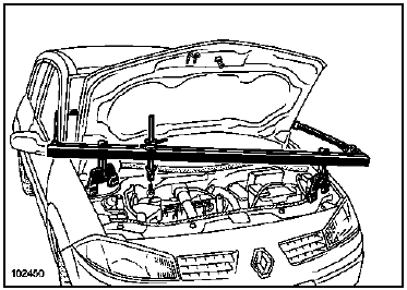
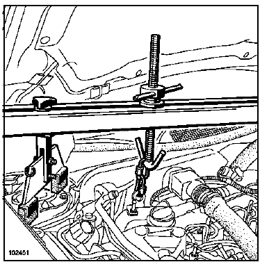
- Fit tool (Mot. 1453) and tool (Mot.1453-01) with the retaining straps.
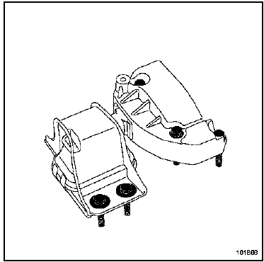
- Remove:
- the "pendulum suspension - engine" assembly,
- the lower torque rod.
CAUTION Do not damage the air conditioning line
K4J
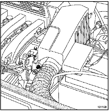
- Remove:
- the air resonator mounting,
- the air resonator.
K4M
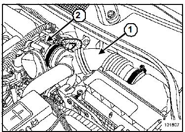
- Remove:
- the air filter outlet duct (1),
- the throttle body (2),
- the connector on the lifting eye.
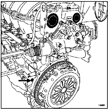
- Remove:
- the camshaft blanking plugs,
- the TDC pin plug.
TIMING BELT TIMING
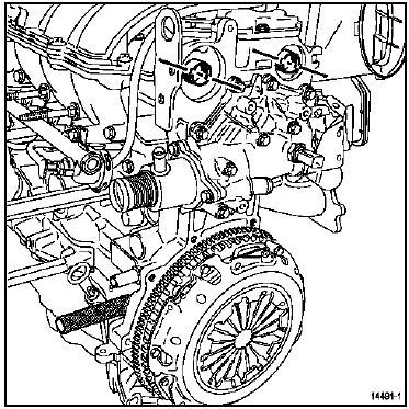
- Position the camshaft grooves downward (as shown in the illustration).
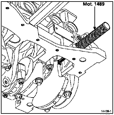
- Screw in the TDC pin (Mot. 1489).
- Turn the engine clockwise (timing side).
- Slowly and smoothly bring the crankshaft to rest against the pin.
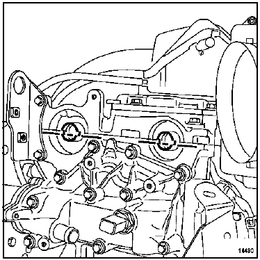
- Check that the camshaft grooves are horizontal and offset downward.
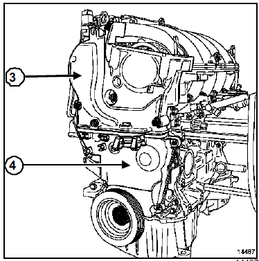
- Remove:
- the crankshaft pulley while locking the flywheel with a screwdriver,
- the upper timing cover (3),
- the lower timing cover (4).
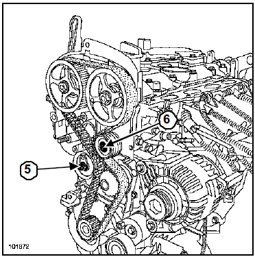
- Release the timing belt tension by unscrewing nut (5) of the tensioner pulley.
- Remove:
- the idler pulley (6) using tool (Mot. 1368),
- the timing belt, taking care not to drop the crankshaft sprocket.
REFITTING - PROCEDURE 1
I - TIMING BELT TIMING
- Procedure 1 applies when replacing any component located at the timing end of the engine that does not require loosening one or more camshaft pulleys.
Thoroughly degrease:
- the crankshaft nose,
- the bore and bearing faces of the timing sprocket,
- the bearing faces of the crankshaft accessory pulley.
- This is to prevent slippage between:
- the crankshaft,
- the camshaft pulleys.
- This slippage will destroy the engine.
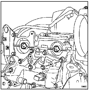
- Position the camshaft grooves horizontally and offset downward.
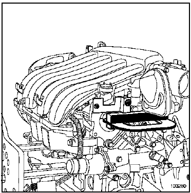
- Fit tool (Mot. 1496) to the ends of the camshafts.
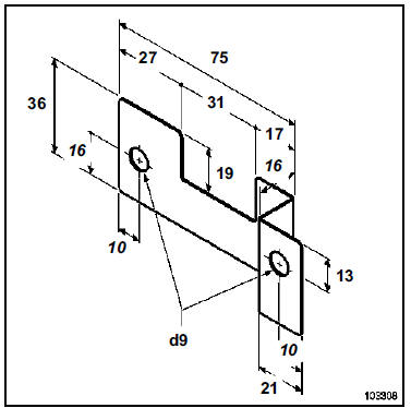
- Make a locally manufactured bracket to hold tool (Mot. 1496) in place (for K4M engine).
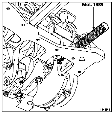
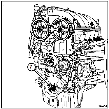
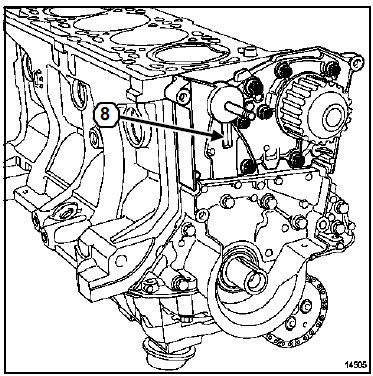
- Check that the crankshaft is resting on the TDC pin (Mot. 1489) (the crankshaft groove (7) must face upward).
II - REFITTING
When replacing the timing belt as recommended by the manufacturer, the timing belt, tensioner pulley and idler pulley must always be replaced.
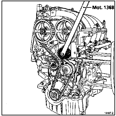
- Refit:
- the timing belt,
- the idler pulley.
- Tighten the idler pulley mounting bolt to torque (4.5 daN.m) using tool (Mot. 1368).
III - BELT TENSIONING
- There are two versions of tensioner pulley.
First version
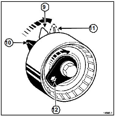
- Using a 6 mm hex key at (12), move the moving pointer (11) of the tensioner pulley so that it protrudes 7 to 8 mm beyond the fixed pointer (9).
Note: Position (10) corresponds to the moving pointer at rest.
Second version
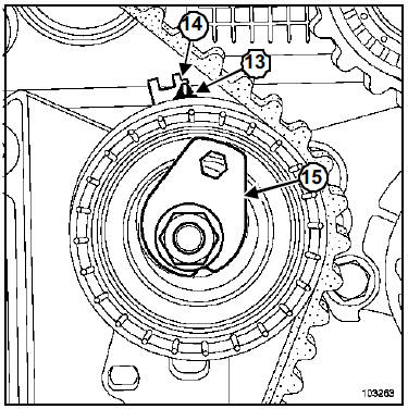
- Using a 6 mm hex key, bring the moving pointer (13) in line with the notch (14) by turning the eccentric (15) clockwise.
- Tighten the tensioner pulley nut to torque (0.7 daN.m)
- Refit the crankshaft accessory pulley.
- The crankshaft pulley bolt may be reused if the length under head does not exceed 49.1 mm.
- Do not oil the new bolt. Oil the bolt without fail if it is reused.
- Tighten the crankshaft accessory pulley bolt to torque and angle (4 daN.m + 115 +/- 15 ) (crankshaft resting against the TDC pin).
- Remove:
- tool (Mot. 1496),
- the TDC pin (Mot. 1489).
- Turn the crankshaft two full turns clockwise (timing side); before the end of the two turns:
- screw the TDC pin (Mot. 1489) into the cylinder block,
- slowly and smoothly bring the crankshaft to rest against the TDC pin.
- Remove the TDC pin (Mot. 1489).
- Loosen the tensioner pulley nut by one turn maximum, while holding the moving pointer with a 6 mm hex key.
- For the first version of tensioner pulley, align the moving pointer (11) with the fixed pointer (9).
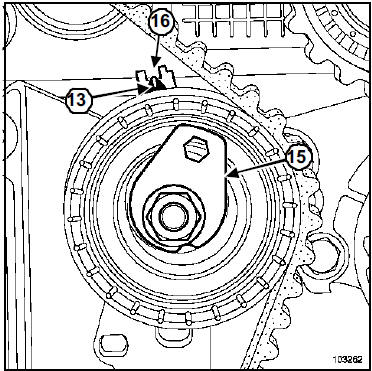
- For the second version of tensioner pulley, gradually bring the moving pointer (13) back to the middle of the timing window (16) by turning the eccentric (15) anticlockwise.
- Tighten the tensioner pulley nut to torque (2.7 daN.m).
IV - CHECKING TIMING AND TENSION
1 - Checking tension
- Turn the crankshaft two full turns clockwise (timing side).
- Before the end of the two turns, screw in the TDC pin (Mot. 1489).
- Slowly and smoothly bring the crankshaft to rest against the TDC pin (Mot. 1489).
- Remove the TDC pin.
Check that the tensioner pulley pointers are aligned; otherwise repeat the tensioning procedure.
2 - Checking timing
- Make sure the tensioner pulley pointers are correctly positioned before checking the timing.
- Screw the TDC pin (Mot. 1489) into the cylinder block.
- Slowly and smoothly bring the crankshaft to rest against the pin.
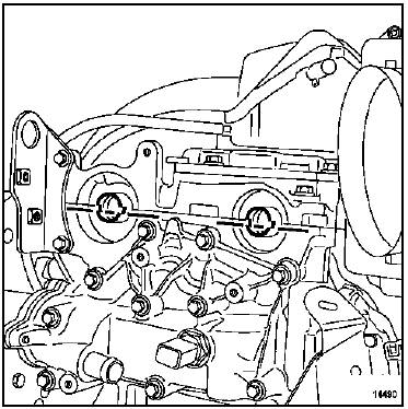
- Fit the camshaft timing tool (Mot. 1496) without forcing (the camshaft grooves must be horizontal and offset downward).
If the tool does not engage, redo the timing alignment and belt tensioning.
REFITTING - PROCEDURE 2
I - TIMING BELT TIMING
- The second procedure applies when replacing any component that requires loosening one or more camshaft pulleys.
- Always replace the camshaft pulley bolts.
- Thoroughly degrease:
- the crankshaft nose,
- the bore and bearing faces of the timing sprocket,
- the bearing faces of the crankshaft auxiliary pulley,
- the camshaft ends (timing belt side),
- the bores and bearing faces of the camshaft pulleys.
- This is to prevent slippage between:
- the crankshaft,
- the camshaft pulleys.
- This slippage will destroy the engine.
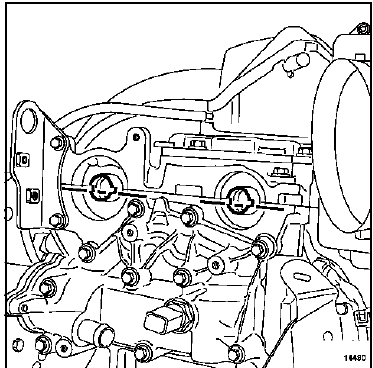
- Position the camshaft grooves horizontally and offset downward.
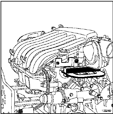
- Fit tool (Mot. 1496) to the ends of the camshafts.
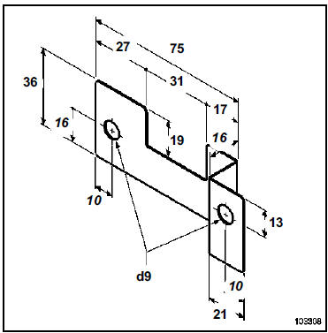
- Make a locally manufactured bracket to hold tool (Mot. 1496) in place (for K4M engine).
- Fit the camshaft pulleys, screwing on the new bolts loosely (do not lock the bolts; leave a gap of 0.5 to 1 mm between the bolt and the pulley).
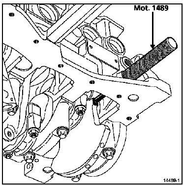
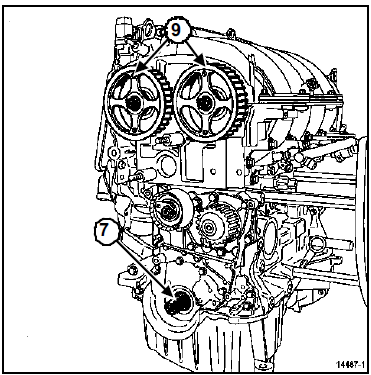
- Check that the crankshaft is resting on the TDC pin (Mot. 1489) (the crankshaft keyway (7) facing upward).
When replacing the timing belt as recommended by the manufacturer, the timing belt, tensioner pulley and idler pulley must always be replaced.
II - REFITTING
On engines without a camshaft phaser, position the RENAULT logo engraved on the camshaft pulley arms vertically and facing upward (9).
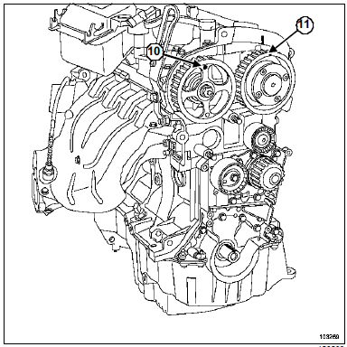
- On engines with a camshaft phaser, position the RENAULT logo (10) engraved on the exhaust camshaft pulley arm, and the mark (11) engraved on the intake camshaft phaser, vertically and facing upward.
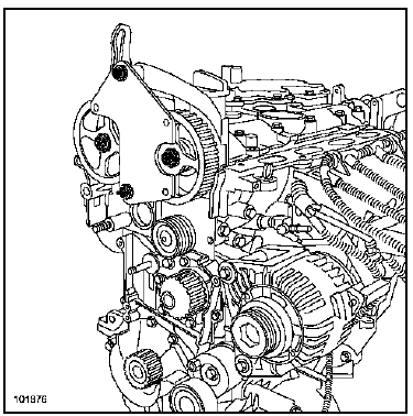
- Refit:
- the timing belt on the camshaft pulleys,
- the camshaft pulley locking tool (Mot. 1490-01) (use the timing cover fixing points to secure tool Mot. 1490-01).
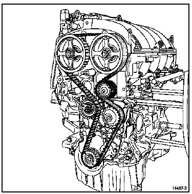
- Refit the idler roller.
- Tighten the idler pulley mounting bolt to torque (4.5 daN.m) using tool (Mot. 1368).
- Fit the crankshaft auxiliary pulley (do not lock the bolt; leave a gap of 2 to 3 mm between the bolt and the pulley).
III - BELT TENSIONING
- There are two versions of tensioner pulley.
First version
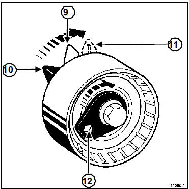
- Using a 6 mm hex key at (12), move the moving pointer (11) of the tensioner pulley so that it protrudes 7 to 8 mm beyond the fixed pointer (9).
Note: Position (10) corresponds to the moving index at rest.
Second version
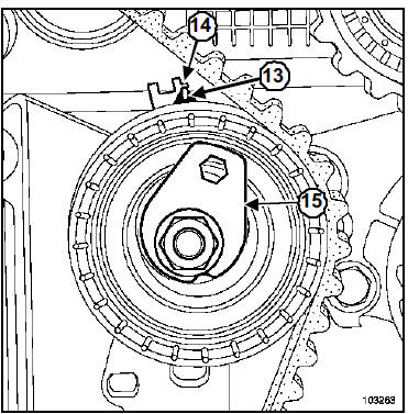
- Using a 6 mm hex key, bring the moving pointer (13) in line with the notch (14) by turning the eccentric (15) clockwise.
- Pre-tighten the tensioner roller nut to torque (0.7 daN.m).
- Remove the camshaft pulley locking tool (Mot. 1490-01).
- Turn the timing belt six full revolutions using the exhaust camshaft pulley, using tool (Mot. 799-01).
- For the first version of tensioner pulley, align the moving pointer (11) with the fixed pointer (9).
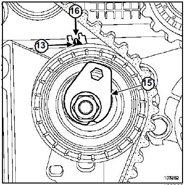
- For the second version of tensioner pulley, gradually bring the moving pointer (13) back to the middle of the timing window (16) by turning the eccentric (15) anticlockwise.
- Tighten the tensioner pulley nut to torque (2.7 daN.m).
- Remove the crankshaft pulley.
- Fit the lower timing cover.
- Refit the crankshaft pulley.
- The crankshaft pulley bolt may be reused if the length under head does not exceed 49.1 mm.
- Do not oil the new bolt. Oil the bolt without fail if it is reused.
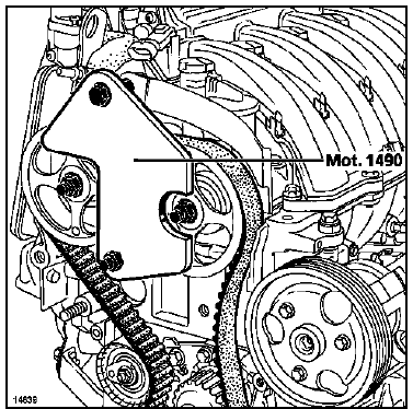
- Fit the camshaft pulley locking tool (Mot. 1490-01).
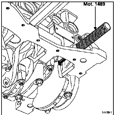
Check that the crankshaft is resting on the TDC pin (Mot. 1489).
- Tighten the crankshaft auxiliary pulley bolt to torque and angle (4 daN.m + 115 +/- 15°) (crankshaft resting on the TDC pin).
- Tighten the new camshaft pulley nuts to torque and angle (3 daN.m + 84 +/-4°), starting with the exhaust pulley.
- Tighten to the following torques:
- the camshaft phaser pulley bolt (7.5 daN.m),
- the phaser pulley plug (1.5 daN.m).
- Remove:
- tool (Mot. 1496),
- the camshaft pulley locking tool (Mot. 1490-01),
- the TDC pin (Mot. 1489).
IV - CHECKING TIMING AND TENSION
1 - Checking tension
- Turn the crankshaft two full turns clockwise (timing side); before the end of the two turns:
- screw the TDC pin (Mot. 1489) into the cylinder block,
- slowly and smoothly position the crankshaft resting on the TDC pin (Mot. 1489).
- Remove the TDC pin (Mot. 1489).
Check that the idler roller indexes are aligned; otherwise repeat the tensioning procedure.
2 - Checking timing
- Make sure the tensioner pulley pointers are correctly positioned before checking the timing.
- Screw the TDC pin (Mot. 1489) into the cylinder block.
- Slowly and smoothly bring the crankshaft to rest against the pin.
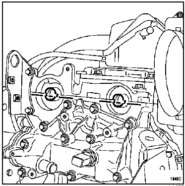
- Fit the camshaft timing tool (Mot. 1496) without forcing (the camshaft grooves must be horizontal and offset downward).
If the tool does not engage, redo the timing alignment and belt tensioning.
INSTALLATION
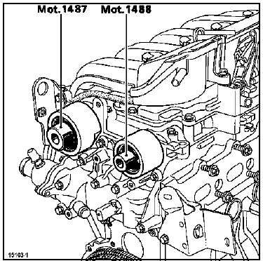
- Refit:
- the auxiliary drive belt (Chapter Upper and front engine, Auxiliary drive belt, page 11A-1),
- new sealing plugs for the intake camshaft (Mot. 1487),
- new sealing plugs for the exhaust camshaft (Mot. 1488),
- the engine pendulum mount (Chapter Engine mounting).
Connect the battery; carry out the necessary re-learns (see Electrical Equipment chapter).
K9K
Essential special tools |
|
| Mot. 1453 | Multi-adjustable engine mounting bracket, with retaining straps |
| Mot. 1453-01 | Additional crank nut for engine lifting support Mot. 1453 |
| Mot. 1489 | TDC timing pin |
| Mot. 1430 | |
Tightening torques |
|
| tensioner roller bolt | 2.5 daN.m |
| crankshaft auxiliary pulley fixing bolt | 2 daN.m + 130 +/- 15° |
| tensioner pulley fixing nut | 2.5 daN.m |
| TDC pin plug | 2 daN.m |
| cylinder head pendulum bracket fixing bolt | 2.1 daN.m |

CAUTION Never turn the engine in the reverse direction to normal operation.
REMOVAL
- Position the vehicle on a two-post lift.
- Disconnect the battery.
- Remove the auxiliary drive belt (Chapter Upper and front engine, Auxiliary drive belt, page 11A-1).
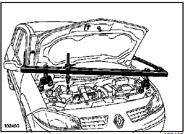
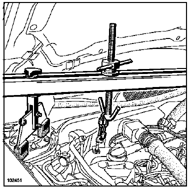
- Fit tools (Mot. 1453) and (Mot. 1453-01) with the retaining straps.
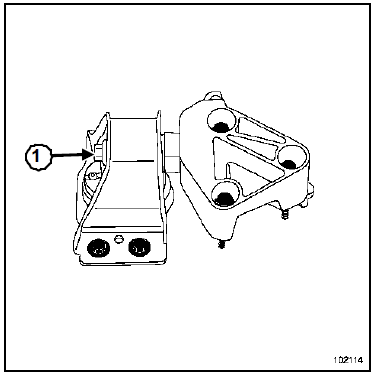
- Loosen bolt (1) and remove the engine pendulum bracket.
CAUTION: Do not deform the air conditioning pipes.
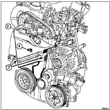
- Remove:
- the upper timing cover by unclipping its two tabs,
- the high-pressure pump position sensor (2).
- Remove the plastic bolt (4).
- Unclip the three tabs (3).
- Remove the lower timing cover.
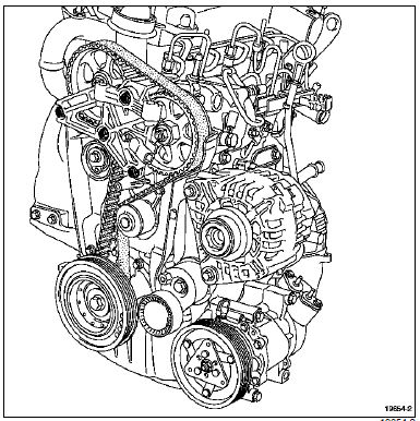
- Remove the cylinder head pendulum bracket.
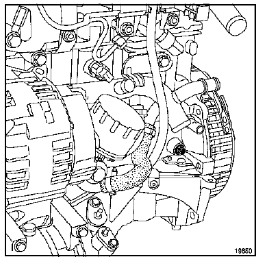
- Remove the TDC pin plug.
Timing belt positioning at the timing mark
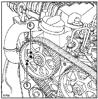
- Turn the engine to position the hole (5) in the camshaft pulley almost opposite the hole (6) in the cylinder head.
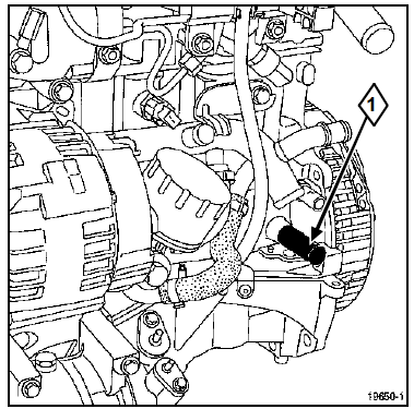
- Screw in the TDC pin (1) (Mot. 1489).
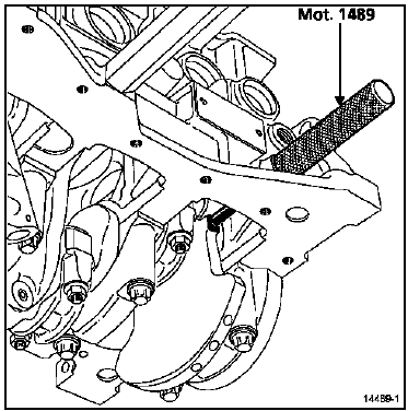
- Turn the engine smoothly clockwise (timing belt side) until the crankshaft rests on the TDC pin (Mot. 1489).
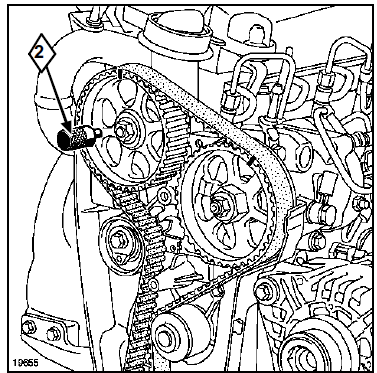
- Insert the pin (2) (Mot. 1430) into the holes in the camshaft pulley and the cylinder head.
- Remove:
- the pin (Mot. 1430),
- the TDC pin (Mot. 1489).
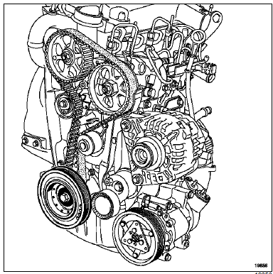
- Remove the crankshaft auxiliary pulley, locking the flywheel with a screwdriver.
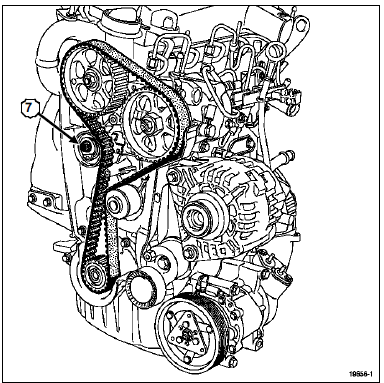
- Loosen the timing belt tensioner roller bolt (7) to release the timing belt tension.
- Remove the timing belt.
INSTALLATION
WARNINGWhen replacing the timing belt, the manufacturer requires that the belt and the tensioner roller are always replaced.
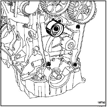
- Refit the timing belt tensioner roller.
TIMING BELT TIMING
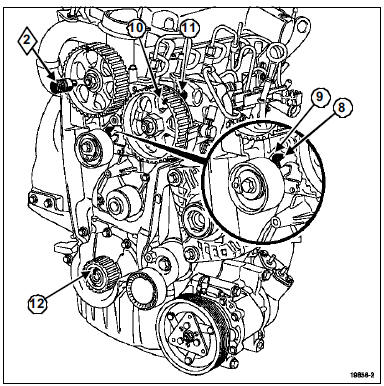
Thoroughly degrease:
- the crankshaft nose,
- the bore and bearing faces of the timing sprocket,
- the bearing faces of the accessory pulley.
- This is to prevent slippage between:
- the crankshaft,
- the camshaft pulley.
- This slippage will destroy the engine.
- Insert the pin (Mot. 1430) into the holes in the camshaft pulley and the cylinder head.
- Check that:
- the mark on the high-pressure pump pulley (10) is opposite the bolt head (11),
- the crankshaft is resting on the TDC pin (Mot. 1489) (the crankshaft keyway (12) facing upward).
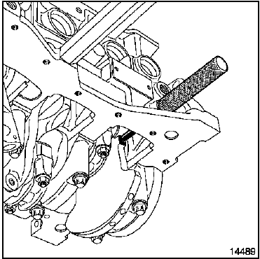
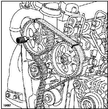
- Fit the timing belt, aligning the belt marks with those on the camshaft and high-pressure pump sprockets (19 belt tooth gaps between the camshaft and pump sprocket marks).
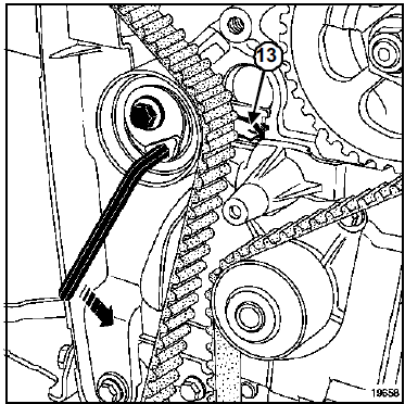
- Bring the moving index (13) of the tensioner roller opposite the lug using a 6 mm Allen key, turning counterclockwise.
- Tighten the tensioner roller bolt to torque (2.5 daN.m).
- Refit the crankshaft accessory pulley.
- Tighten the crankshaft accessory drive pulley bolt to torque and angle (2 daN.m + 130 +/- 15) (crankshaft held at the TDC pin).
- Remove:
- the TDC pin (Mot. 1489),
- the camshaft pulley timing pin (Mot.1430).
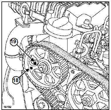
- Turn the crankshaft two full turns clockwise (timing side).
- Before the hole (18) in the camshaft pulley lines up with the hole (19) in the cylinder head, screw the TDC pin (Mot. 1489) into the cylinder block.
WARNING: Never turn the engine against its normal direction of rotation.
- Slowly position the crankshaft against the pin without jerking.
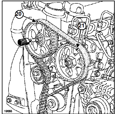
- Check that:
- the timing pin (Mot. 1430) engages correctly in the holes of the camshaft pulley and the cylinder head,
- there are 19 belt tooth gaps between the marks on the camshaft sprocket (20) and the high-pressure pump sprocket (21).
- Remove:
- the TDC pin (Mot. 1489),
- the camshaft pulley timing pin (Mot.1430).
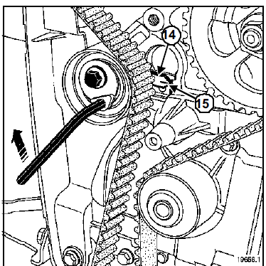
- Loosen the tensioner pulley bolt by one turn maximum while holding it with a 6 mm hex key.
- Gradually align the moving pointer (14) to the middle of the timing window (15), turning the key clockwise.
- Torque the tensioner pulley nut (2.5 daN.m).
- Refit the TDC pin plug, applying a drop of RHODORSEAL 5661 to the thread.
- Torque the TDC pin plug (2 daN.m).
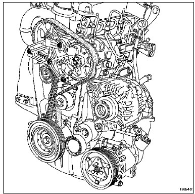
- Refit the cylinder head pendulum bracket.
- Torque the cylinder head pendulum bracket bolts (2.1 daN.m).
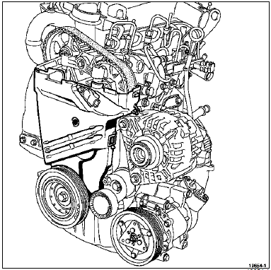
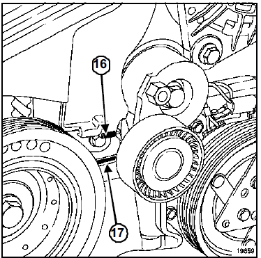
- Refit the lower timing cover, positioning the tab (16) in the opening (17) of the lower timing cover.
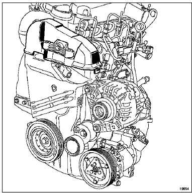
- Refit:
- the upper timing cover,
- the engine pendulum mount (see Engine Mounting chapter),
- the accessory drive belt (see Engine Top and Front chapter).
- Refit in the reverse order of removal.
Connect the battery; carry out the necessary re-learns (see Electrical Equipment chapter).
F9Q
Essential special tools |
|
| Mot. 1453 | Multi-adjustable engine mounting bracket, with retaining straps |
| Mot. 1453-01 | Additional crank nut for engine lifting support Mot. 1453 |
| Mot. 1054 | TDC pin |
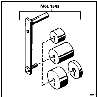
| Mot. 1543 | Timing belt pre-tensioning tool |
| Mot. 1705 | Timing belt pre-tensioning attachment for F9Q engine (33 teeth) |
| Mot. 1505 | Belt tension checker (frequency meter) |
Tightening torques |
|
| tensioner pulley fixing nut | 5 daN.m |
| accessory drive pulley bolt | 4 daN.m + 110 +/- 10 |

CAUTION Never turn the engine in the reverse direction to normal operation.
REMOVAL
- Position the vehicle on a two-post lift.
- Disconnect the battery.
- Remove:
- the engine undershield,
- the drive belt (Chapter Upper and front engine, Drive belt, page 11A-1).
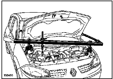
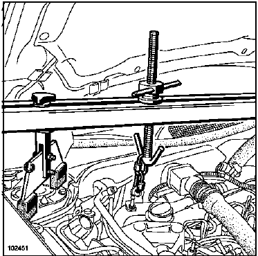
- Fit tools (Mot. 1453) and (Mot. 1453-01) with the retaining straps.
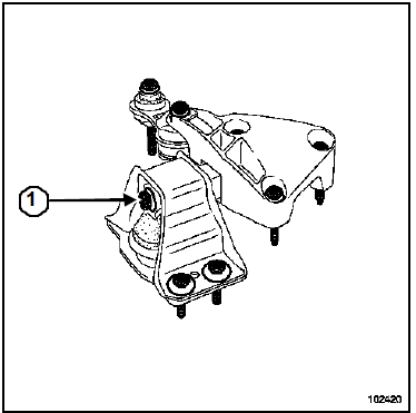
- Loosen bolt (1) and remove the engine pendulum mount bracket.
- Remove:
- the upper torque link,
- the lower torque rod.
CAUTION: Do not deform the air conditioning pipes.
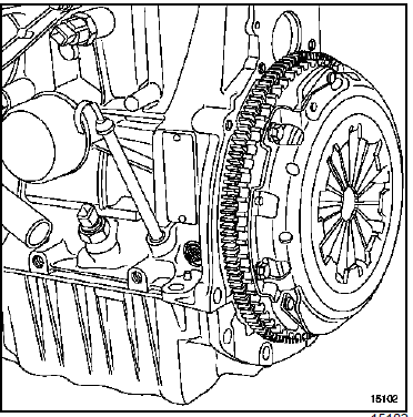
- Remove the TDC pin plug.
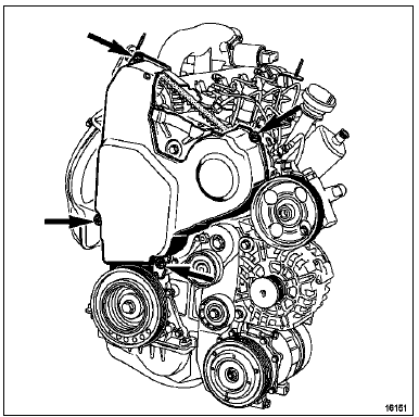
- Remove:
- the flywheel access cover,
- the accessory drive pulley, holding the flywheel with a screwdriver,
- the timing cover.
TIMING BELT TIMING
- Turn the crankshaft clockwise (timing side). As soon as the camshaft pulley mark is half a tooth before the mark on the protective plate, press the TDC pin (Mot. 1054) until the crankshaft locks.
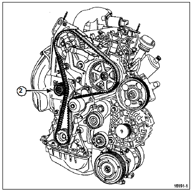
- Loosen the tensioner pulley nut (2) to release tension on the tensioner pulley.
- Remove the timing belt.
INSTALLATION
WARNINGWhen replacing the timing belt as specified by the manufacturer, the belt and the tensioner pulley must always be replaced.
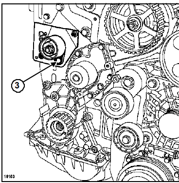
- Check that the tensioner pulley is correctly seated on the locating pin (3).
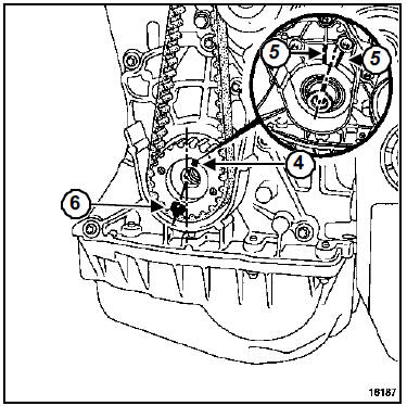
- Check that the TDC pin (Mot. 1054) is in place.
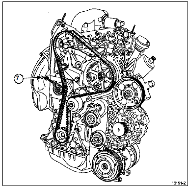
- Fit the new timing belt, aligning the belt marks with those of the camshaft and crankshaft sprockets.
- Bring the tensioner pulley into contact with the belt by screwing bolt (7) into the tensioner pulley bracket.
Note: Bolt (7) is locally manufactured.
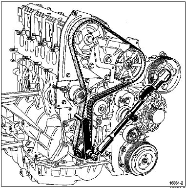
- Remove the TDC pin (Mot. 1054).
- Fit the accessory drive pulley bolt.
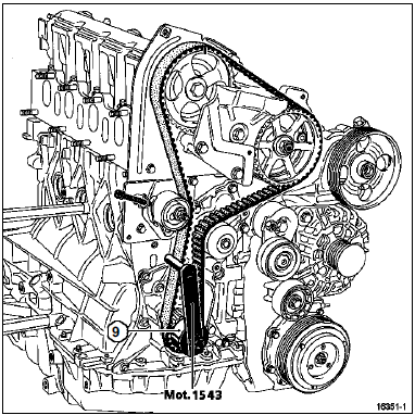
- Fit tool (Mot. 1543) with adaptor (Mot. 1705) (9) onto the accessory drive pulley bolt.
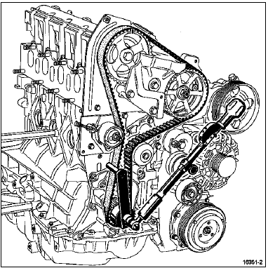
- Apply pre-tension between the crankshaft timing sprocket and the tensioner pulley using tool (Mot. 1543) and a torque wrench set to 1.1 daN.m.
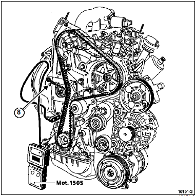
- Place the sensor of tool (Mot. 1505) between the crankshaft sprocket and the tensioner pulley.
- Tension the belt to the specified value of 95 +/- 3 Hz by turning bolt (8).
- Tighten the tensioner pulley nut to torque (1 daN.m).
WARNING: Never turn the engine against its normal direction of rotation.
- Turn the crankshaft two full turns.
- Reinstall the TDC pin (Mot. 1054).
- Set the timing to its timing point (start engaging the pin half a tooth before the camshaft pulley mark lines up with the mark on the inner timing cover, to avoid dropping into a crankshaft balance hole).
- Remove the TDC pin (Mot. 1054).
- Apply pre-tension between the crankshaft timing sprocket and the tensioner pulley using tool (Mot. 1543) and a torque wrench set to 1.1 daN.m.
- Place the sensor of tool (Mot. 1505) between the crankshaft sprocket and the tensioner pulley.
- Check that the tension value is 90 +/- 3 Hz; if not, readjust.
- Torque the tensioner pulley nut (5 daN.m).
- Remove tool (Mot. 1543).
- Refit the crankshaft accessory pulley.
- Tighten the accessory drive pulley bolt to torque and angle (4 daN.m + 110 +/- 10).
- Refit:
- the right-hand pendulum mount, tightening it to torque (see Engine Mounting chapter, Setting value
- pendulum mount, page 19D-1),
- the drive belt (Chapter Upper and front engine, Drive belt, page 11A-1).
- Refit in the reverse order of removal.
Connect the battery; carry out the necessary re-learns (see Electrical Equipment chapter).
F4R
Essential special tools |
|
| Mot. 1453 | Multi-adjustable engine mounting bracket, with retaining straps |
| Mot. 1453-01 | Additional crank nut for engine lifting support Mot. 1453 |
| Mot. 1054 | TDC pin |
| Mot. 799-01 | Timing belt sprocket locking tool |
| Mot. 1496 | Camshaft timing tool |
| Mot. 1509 | Camshaft sprocket locking tool |
| Mot. 1487 | Camshaft cover refitting tool |
| Mot. 1488 | Camshaft covers refitting tool |
Tightening torques |
|
| idler pulley fixing bolt | 5 daN.m |
| tensioner pulley nut | 2,8 daN.m |
| exhaust and intake camshaft pulley nuts | 3 daN.m + 86 +/- 6 |
| accessory drive pulley bolt | 4 daN.m + 110 |
| upper pendulum mount link bolt | 10.5 daN.m |
| engine-side bolt of the pendulum mount cover | 6.2 daN.m |
| wheel bolt | 11 daN.m |

- Never turn the engine against its normal direction of rotation.
- Fitting the crankshaft sprocket with the integrated key is mandatory for the F4R engine.
- Always replace the following during this operation:
- the camshaft pulley nuts,
- the tensioner and idler pulleys,
- the crankshaft accessory drive pulley,
- the crankshaft accessory drive pulley bolt.
REMOVAL
- Position the vehicle on a two-post lift.
- Disconnect the battery.
- Remove:
- the front right wheel,
- the right front wheel arch,
- the engine covers.
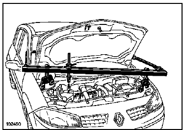
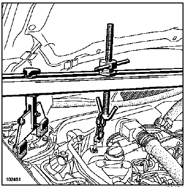
- Fit tools (Mot. 1453) and (Mot. 1453-01) with the retaining straps.
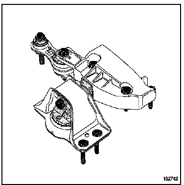
- Remove the pendulum mount assembly.
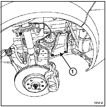
- Remove:
- the right-hand side reinforcement of the radiator crossmember (1),
- the lower torque rod.
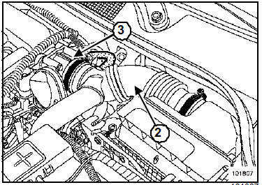
- Remove:
- the air filter outlet duct (2),
- the throttle body (3),
- the connector on the lifting eye.
- Remove the auxiliary drive belt (Chapter Upper and front engine, Auxiliary drive belt, page 11A-1).
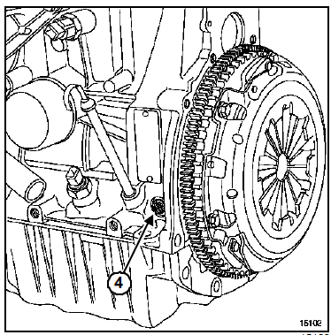
- Remove the TDC plug (4).
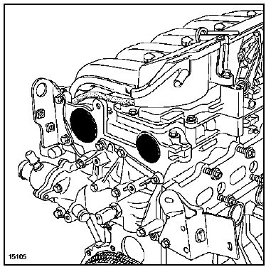
- Remove the camshaft seal plugs.
I - TIMING BELT TIMING
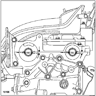
- Turn the engine clockwise (timing side) so that the camshaft grooves point downwards into an almost horizontal position, as shown in the illustration.
- Insert the TDC locating pin (Mot. 1054) so that it sits between the balance hole and the crankshaft locating groove.
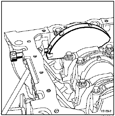
- Turn the engine slightly in the same direction, engaging the TDC locating pin (Mot. 1054) up to the setting point.
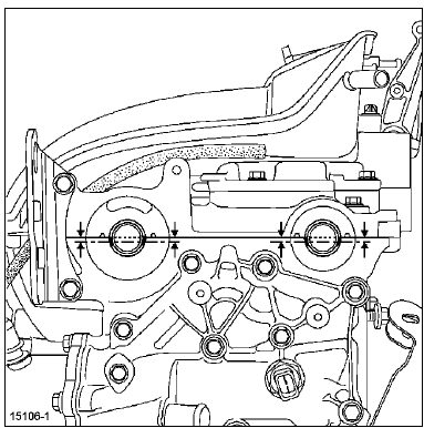
- At the setting point, the camshaft grooves must be horizontal and pointing downwards, as shown in the illustration.
Correct position
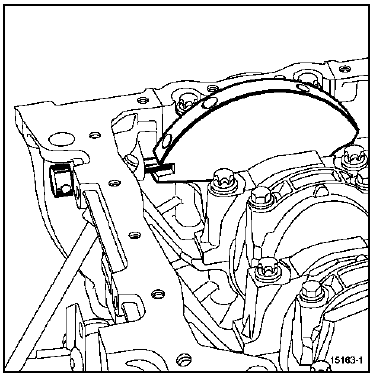
Incorrect position
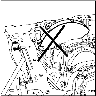
- The pin is in the balance hole.
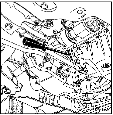
- Remove:
- the flywheel cover,
- the crankshaft pulley, locking the flywheel with a screwdriver.
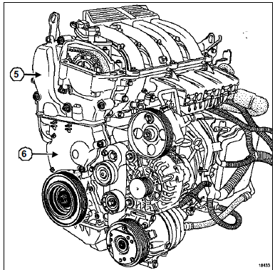
- Remove:
- the upper timing cover (5),
- the lower timing cover (6).
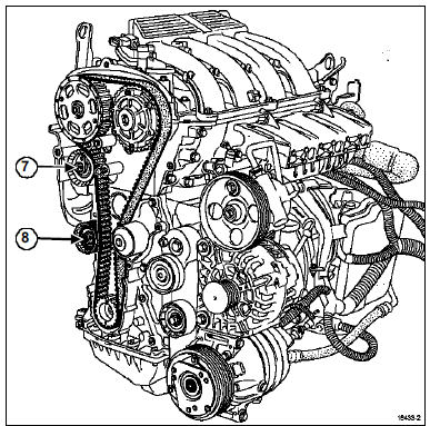
- Loosen the timing belt tension by unscrewing the tensioner roller nut (7).
- Remove:
- the idler pulley (8),
- the timing belt,
- the crankshaft timing sprocket.
- When replacing the timing belt as recommended by the manufacturer, the timing belt, tensioner pulley and idler pulley must always be replaced.
- Never turn the engine against its normal direction of rotation.
II - TIMING ALIGNMENT
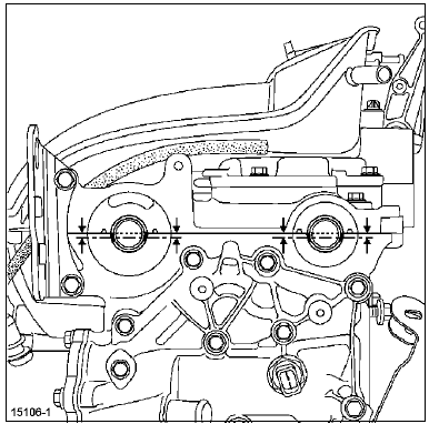
- Position the camshaft grooves using tool (Mot. 799-01) as shown in the illustration.
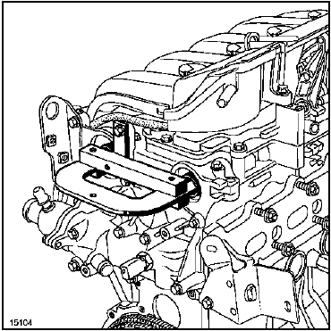
- Fit tool (Mot. 1496), attaching it to the ends of the camshafts.
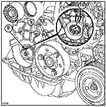
- Check that the crankshaft is correctly locked at TDC and not in the balance hole (the crankshaft groove (9) must be centred between the two ribs (10) of the crankshaft cover).
Correct position
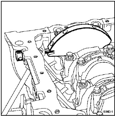
Incorrect position
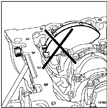
- Loosen the exhaust and intake camshaft pulleys.
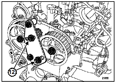
- Fit the camshaft locking tool (Mot. 1509) while tightening the nuts (12) to 8 daN.m.
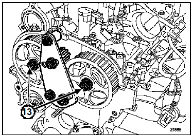
- Remove the nuts (13) from the exhaust and intake pulleys.
- Remove tool (Mot. 1509).
- Thoroughly degrease the bores and bearing faces of the camshaft pulleys.
- This is to prevent slippage between:
- the timing belt,
- the camshaft pulleys.
- This slippage will destroy the engine.
- Refit the camshaft pulleys.
When replacing the timing belt, always replace:
- the crankshaft accessory drive pulley,
- the tensioner and idler pulleys,
- the crankshaft sprocket (if it is not fitted with an integrated key).
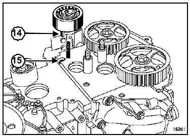
- Make sure the lug (14) of the tensioner roller is correctly located in the groove (15).
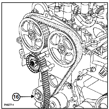
- Refit:
- the timing sprocket (fitted with an integrated key),
- the timing belt,
- the idler pulley (16).
- Torque tighten the idler pulley mounting bolt (5 daN.m).
III - BELT TENSIONING
Note: Do not turn the tensioner roller anticlockwise.
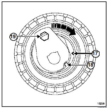
- Align the marks (17) and (18) on the tensioner roller using a 6 mm Allen key at (19).
- Pre-tighten the tensioner roller nut to 0.7 daN.m.
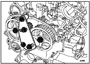
- Fit the camshaft pulley locking tool (Mot. 1509).
- Pre-tighten the new intake and exhaust camshaft pulley nuts to 3 daN.m.
- Remove tools (Mot. 1509), (Mot. 1496) and (Mot. 1054).
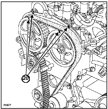
- Make a mark (20) with a pencil between the camshaft pulleys and the camshaft bearing cap.
IV - CHECKING TIMING AND TENSION
1 - Checking tension
- Turn the crankshaft two full turns clockwise (timing side).
- Before the end of the two turns (i.e. half a turn before the previously made marks align), insert the crankshaft TDC locating pin (Mot. 1054) so that it sits between the balance hole and the setting hole.
- Bring the timing to its setting point.
Before timing setting
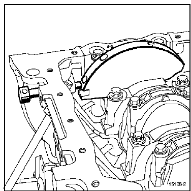
Crankshaft locked
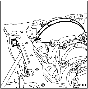
- Check that the tensioner roller marks are correctly aligned; otherwise redo the tensioning as follows:
- fit tools (Mot. 1496) and (Mot. 1509),
- loosen the camshaft pulleys,
- remove tool (Mot. 1509).
- Loosen the tensioner roller nut by a maximum of one turn while holding it with a 6 mm Allen key.
- Align the tensioner roller marks.
- Torque tighten the tensioner roller nut (2.8 daN.m).
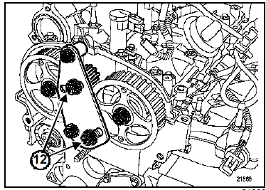
- Fit the camshaft locking tool (Mot. 1509) while tightening the nuts (12) to 8 daN.m.
- Remove the old pulley nuts and replace them with new nuts.
- Torque and angle tighten the exhaust and intake camshaft pulley nuts (3 daN.m + 86 +/- 6).
- Remove:
- tool (Mot. 1496),
- the camshaft pulley locking tool (Mot. 1509),
- the crankshaft TDC locating pin (Mot. 1054).
2 - Checking timing
- Turn the crankshaft two full turns clockwise.
- Fit the TDC locating pin (Mot. 1054) (check that the marks made earlier on the pulleys
Test yourself
A quick Renault Megane quiz: every answer comes with an explanation and a link to the manual page.