Cylinder head gasket
K4J or K4M
Essential special tools |
|
| Mot. 1202-01 | Spring clamp pliers (large model) |
| Mot. 1202-02 | Spring clamp pliers (small model) |
| Mot. 1367-02 | Engine support |
| Mot. 1490-01 | Camshaft pulley locking tool |
| Mot. 1669 | Fitting the counter-cam pusher |
| Mot. 1632 | Camshaft seal fitting tool |
| Mot. 1512 | Camshaft seal fitting tool (28 x 47) |
| Mot. 1487 | Camshaft cover refitting tool |
| Mot. 1488 | Camshaft covers refitting tool |
Essential equipment |
| cylinder head test tools |
Tightening torques |
|
| bearing housing mounting bolts no. 22, 23, 20, 13 | 0.8 daN.m |
| camshaft "bearing cap" mounting bolts no. 1 to 12, 14 to 19, 21 to 24 | 1.2 daN.m |
| oil separator mounting bolts (new) in unthreaded holes (K4J engine) | 1.5 daN.m |
| oil separator mounting bolts (new or original) in already threaded holes (K4J engine) | 1 daN.m |
| oil separator mounting bolt (K4M engine) | 1.5 daN.m |
| ignition coil mounting bolts | 1.3 daN.m |
| intake manifold mounting bolt | 0.9 daN.m |
| throttle body mounting bolt | 1.5 daN.m |
| air filter housing mounting bolt | 0.9 daN.m |

REMOVAL
- Position the vehicle on a two-post lift.
- Remove the engine covers.
- Disconnect the battery (see Electrical Equipment chapter).
- Remove the undershield.
- Drain the cooling system through the lower radiator hose using tool (Mot. 1202-01) and (Mot. 1202-02).
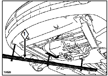
- Fit the engine support (1) (Mot. 1367-02).
- Remove:
- the auxiliary drive belt (Chapter Upper and front engine, Auxiliary drive belt, page 11A-1),
- the timing belt (Chapter Upper and Front Engine, Timing Belt, page 11A-5).
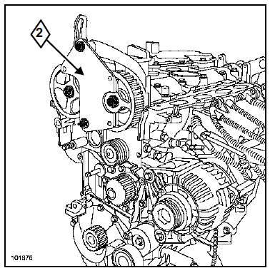
- Remove:
- the camshaft pulleys using camshaft pulley locking tool (2) (Mot. 1490-01),
- the fuel rail protector,
- the fuel supply hose from the fuel rail.
- Move the fuel supply hose aside.
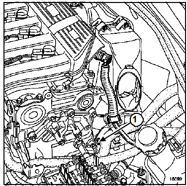
- Remove the mounting bolt of bracket (1).
- Move the bracket and harness assembly aside.
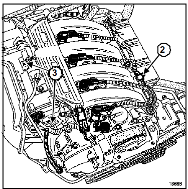
- Disconnect:
- the ignition coil connectors,
- the air temperature sensor connector (2),
- the variable valve timing connector,
- the camshaft position sensor connector,
- the brake booster vacuum hose from the intake manifold.
- Remove:
- the ignition coils,
- the air box at (3) (see Chapter Fuel Metering) (K4J engine only),
- the variable valve timing solenoid valve,
- the camshaft position sensor.
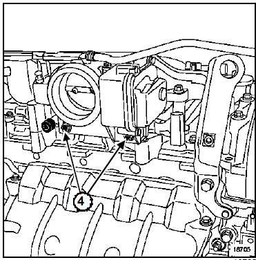
- Remove:
- the throttle body mounting bolts (4),
- the throttle body (see Chapter Fuel Metering).
- Disconnect the catalytic converter oxygen sensor connector.
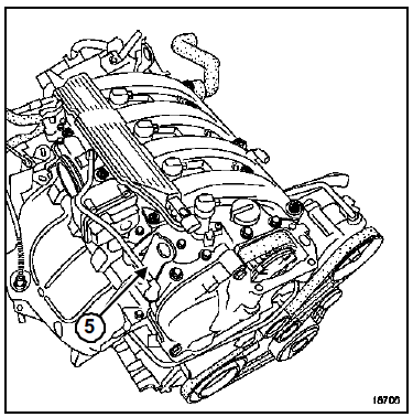
- Remove:
- the lifting eye (5),
- the air distributor.
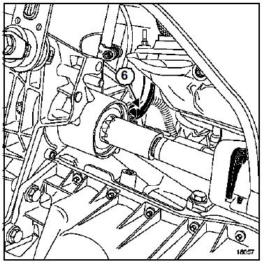
- Remove:
- the bracket (6),
- the exhaust downpipe.
K4J
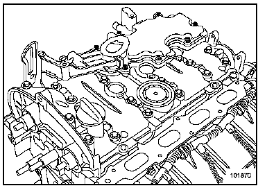
- Remove:
- the oil separator,
- the lifting eye on the flywheel side.
K4M
CAUTION Do not remove the counter-cam retaining bolt.
K4M
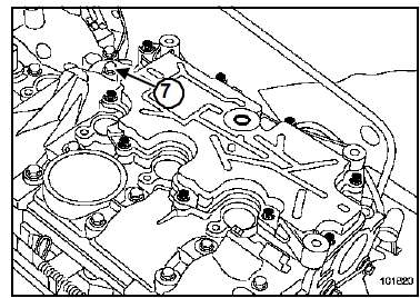
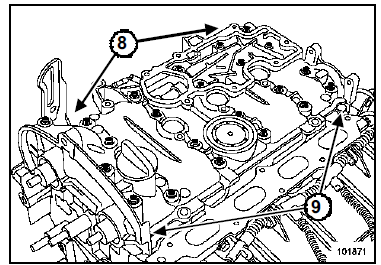
- Remove:
- the "camshaft bearing housing" bolts,
- Lift the "camshaft bearing housing" straight up (tap the "lugs" at (8) with a bronze drift while levering at (9) with a screwdriver.
CAUTION Do not damage the aluminium surfaces (protect the screwdriver).
- Remove:
- the camshafts,
- the rocker arms.
- Disconnect the hoses from the cylinder head coolant housing.
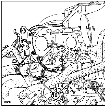
- Disconnect:
- the coolant temperature sensor connector,
- the harness support mounts (10).
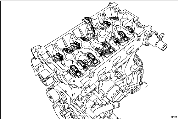
- Remove the cylinder head.
I - CLEANING
- Clean the cylinder head.
IMPORTANT Wear gloves during this operation. Wear safety glasses.
WARNING- Do not scrape the gasket surfaces of the aluminium parts.
- Clean the gasket surfaces with GASKET REMOVER to dissolve the part of the gasket still stuck to the lower housing and the cylinder block.
- Apply the product to the area to be cleaned; wait approximately ten minutes, then remove the residue with a wooden spatula.
- Take great care during this operation to prevent foreign matter from entering the oil galleries (galleries located in the cylinder block and cylinder head).
II - CHECKING THE GASKET SURFACE
- Check the gasket surface for distortion using a straightedge and a set of feeler gauges.
Maximum distortion: 0.05 mm
CAUTION No machining of the cylinder head is permitted.
- Pressure test the cylinder head to detect any cracks, using the cylinder head pressure test equipment (see Garage Equipment Catalogue).
- Set the pistons to mid-stroke to prevent contact with the valves when refitting the camshafts.
INSTALLATION
- Fit the cylinder head gasket.
- Refit the cylinder head.
- Check the cylinder head bolt tightening (see Chapter Powertrain Values and Settings).
- Tighten the cylinder head (see Chapter Powertrain Values and Settings).
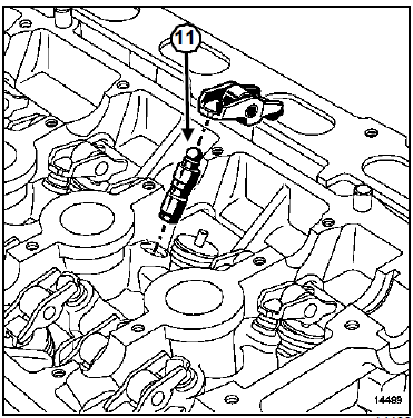
- Prime the hydraulic lash adjusters (the hydraulic lash adjusters may drain after a prolonged removal period).
To check whether they need priming, press down on the top of the lash adjuster (11) with your thumb.
If the lash adjuster piston sinks:
- immerse the lash adjusters in a container full of diesel fuel,
- refit the hydraulic lash adjusters.
- Refit:
- the rocker arms,
- the camshafts, lubricating the bearings with oil.
Do not apply oil to the gasket surface of the "camshaft bearing housing".
I - CAMSHAFT TIMING MARKS
K4J
Intake camshaft
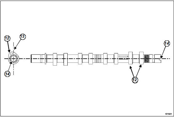
- Position the slot (14) at the camshaft end horizontally (slot below the camshaft axis).
The cams (12) of cylinder 1 must be to the left of the vertical axis (13).
Exhaust camshaft
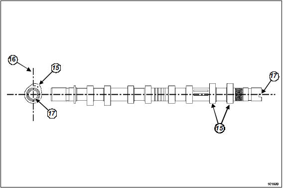
- Position the slot (17) at the camshaft end horizontally (slot below the camshaft axis).
The cams (15) of cylinder 1 must be to the right of the vertical axis (16).
K4M
Note: the camshafts are identified by their pulley mounting bolts.
Intake camshaft
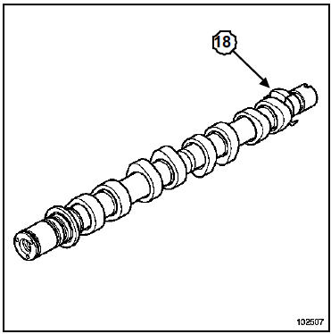
- The intake camshaft is fitted with the camshaft position sensor target (18).
Exhaust camshaft
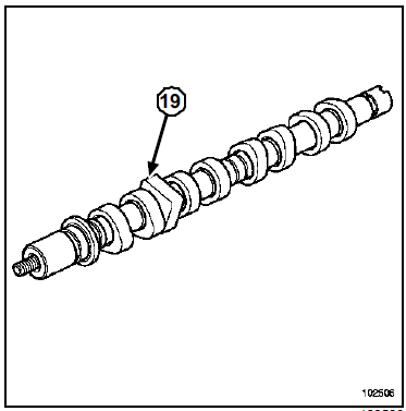
- The exhaust camshaft is fitted with the square cam (19).
- Fit tool (Mot. 1669).
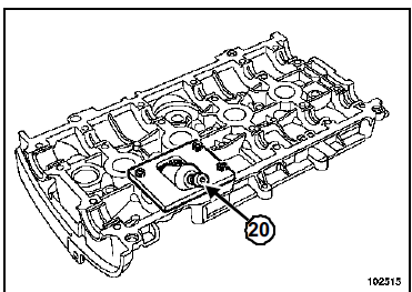
- Compress the counter-cam pusher using bolt (20).
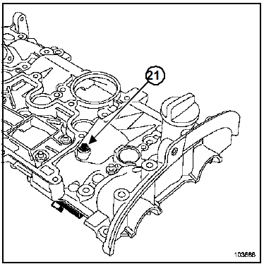
- Fit the bolt of tool (Mot. 1669) at (21) to hold the pusher in the compressed position.
- Remove tool (Mot. 1669).
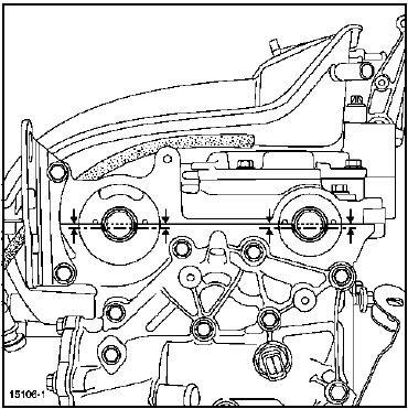
- Position the camshaft groove markings horizontally and offset downward.
- The mating surfaces must be clean, dry and free of grease.
- Excess sealant applied may squeeze out when the parts are tightened. Sealant mixing with the coolant may damage certain components (engine, radiator).
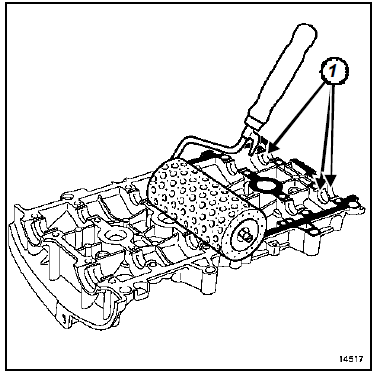
- Apply LOCTITE 518 to the camshaft "bearing cap" mating surface using a (stippling) roller until the surface turns reddish.
- Refit the camshaft "bearing cap" and tighten it to torque.
II - TIGHTENING METHOD
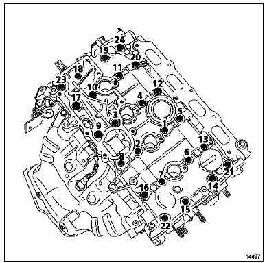
- Pre-tighten in the following sequence and to the torques:
- bearing cap mounting bolts No. 22, 23, 20, 13 (0.8 daN.m),
- camshaft "bearing cap" mounting bolts No. 1 to 12, 14 to 19, 21 to 24 (1.2 daN.m).
- Loosen bolts 22, 23, 20, 13 in sequence.
- Tighten camshaft "bearing cap" mounting bolts No. 22, 23, 20, 13 in sequence and to torque (1.2 daN.m).
K4J
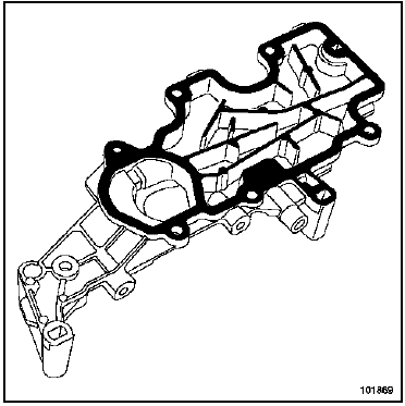
- The mating surfaces must be clean, dry and free of grease.
- Excess sealant applied may squeeze out when the parts are tightened. Sealant mixing with the coolant may damage certain components (engine, radiator).
- Apply LOCTITE 518 to the mating surface using a (stippling) roller until the mating surface turns reddish.
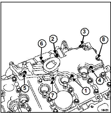
- Refit the oil separator.
- Tighten in sequence and to torque:
- new oil separator mounting bolts in non-tapped holes (K4J engine) (1.5 daN.m),
- new or original oil separator mounting bolts in already-tapped holes (K4J engine) (1 daN.m).
K4M
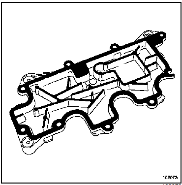
- The mating surfaces must be clean, dry and free of grease.
- Excess sealant applied may squeeze out when the parts are tightened. Sealant mixing with the coolant may damage certain components (engine, radiator).
- Apply LOCTITE 518 to the mating surface using a (stippling) roller until the mating surface turns reddish.
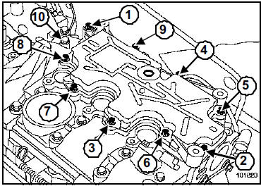
- Refit the oil separator.
- Tighten the oil separator mounting bolts in sequence and to torque (K4M engine) (1.5 daN.m).
- Remove bolt (10) from tool (Mot. 1669) to decompress the tappet.
- Refit the original bolt, applying a drop of LOCTITE FRENETANCH.
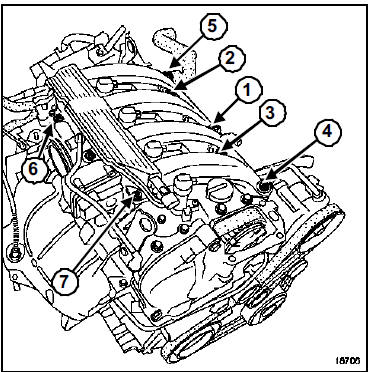
- Refit the ignition coils.
- Tighten the ignition coil mounting bolts to torque (1.3 daN.m).
- Refit the intake manifold fitted with new gaskets.
- Tighten the intake manifold mounting bolts in sequence (1) to (7) and to torque (0.9 daN.m).
- Refit the throttle body.
- Tighten the throttle body mounting bolts to torque (1.5 daN.m).
- Refit the air filter housing.
- Tighten the air filter housing mounting bolts to torque (0.9 daN.m).
- Refit:
- the camshaft phaser solenoid valve and its seal (K4M engine only),
- the camshaft position sensor.
III - REPLACING THE CAMSHAFT OIL SEALS
- Use tool (Mot. 1632) for the intake camshaft seal.
- Use tool (Mot. 1512) for the intake camshaft seal.
IV - REFITTING
- Refit:
- the timing belt (Section Top and front of engine, Timing belt, page 11A-5),
- the auxiliary drive belt (Chapter Upper and front engine, Auxiliary drive belt, page 11A-1),
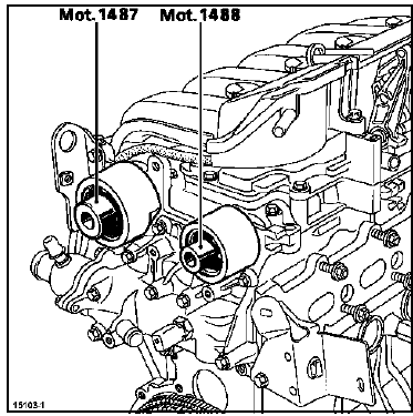
- the new intake camshaft plugs using tool (Mot. 1487),
- the new exhaust camshaft plugs using tool (Mot. 1488),
- the engine pendulum mount (see Section Engine mounting).
- Refit in the reverse order of removal.
- Fill and bleed the cooling system (see Section Cooling).
Connect the battery; carry out the necessary re-learns (see Electrical Equipment chapter).
K9K
Essential special tools |
|
| Mot. 1202-01 | Spring clamp pliers (large model) |
| Mot. 1202-02 | Spring clamp pliers (small model) |
| Mot. 1448 | Remote spring clamp pliers |
| Mot. 1367-02 | Engine support |
Essential equipment |
| cylinder head test tools |
| angle-torque wrench |
Tightening torques |
|
| cylinder head cover mounting bolts | 1 daN.m |
| turbocharger oil return pipe | 0.9 daN.m |

Before any work:
- connect the diagnostic tool (aftermarket),
- communicate with the injection ECU,
- check that the injection rail is no longer pressurised,
- beware of the fuel temperature,
- order the special high-pressure injection circuit plug kit.
REMOVAL
- Position the vehicle on a two-post lift.
- Remove:
- the engine covers,
- the engine undertray.
- Disconnect the battery.
- Drain the cooling system via the lower radiator hose using tool (Mot. 1202-01) or (Mot. 1202-02) and (Mot. 1448)
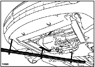
- Fit the engine support using tool (Mot. 1367-02).
- Remove:
- the auxiliary drive belt (Chapter Upper and front engine, Auxiliary drive belt, page 11A-1),
- the timing belt (Chapter Upper and Front Engine, Timing Belt, page 11A-5).
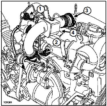
- Disconnect:
- the air temperature and pressure sensor connector (1),
- the exhaust gas recirculation valve control connector (2),
- the air hoses (3),
- the rubber hose of the boost pressure regulator valve,
- the air sleeve on the air filter housing,
- the oil vapour breather hose on the cylinder head cover.
- Remove the resonator housing support bracket (4).
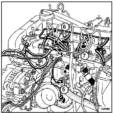
- Disconnect:
- the injector connectors,
- the glow plug connectors,
- the diesel supply hose on the pump,
- the diesel return hose on the pump.
- Remove the wiring and diesel return hose bracket (5).
- Disconnect:
- the fuel temperature sensor (6),
- the fuel flow actuator connector (7).
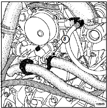
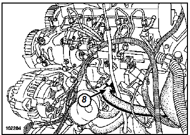
- Disconnect:
- the heater matrix hoses (8),
- the coolant temperature sensor connector on the water box.
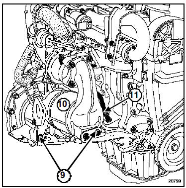
- Remove:
- the exhaust downpipe mountings,
- the two brackets (9),
- the catalytic converter (10).
- Disconnect the turbocharger oil return pipe (11).
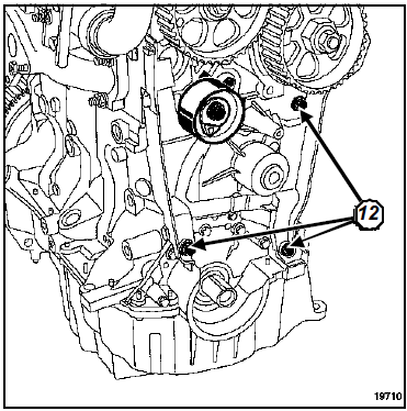
- Remove:
- the timing belt tensioner pulley,
- the accessory belt tensioner pulley,
- the inner timing cover (12).
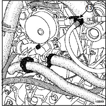
- Disconnect the brake booster hose from the vacuum pump (13).
- Remove:
- the cylinder head cover,
- the cylinder head bolts,
- the cylinder head.
I - CLEANING
- Clean the cylinder head.
- Do not scrape the gasket surfaces of the aluminium parts.
- Wear:
- safety glasses,
- gloves during the operation.
- Clean the mating surfaces with DÉCAPJOINT to dissolve the remaining gasket material stuck to the lower casing and the cylinder block.
- Apply the product to the area to be cleaned; wait approximately ten minutes, then remove the residue with a wooden spatula.
Take care when performing this operation to prevent foreign bodies from entering the oil galleries (galleries located in both the cylinder block and the cylinder head).
WARNING- Protect the oil supply passage to prevent foreign bodies from entering the oil supply pipes to the cylinder head.
- Failure to follow this instruction may block the oil supply passages and cause rapid damage to the camshaft.
The cylinder head bolts must be replaced after each removal and must not be oiled before fitting.
II - CHECKING THE GASKET SURFACE
- Check for distortion of the cylinder head mating face using a straightedge and feeler gauges.
The maximum distortion is 0.05 mm.
WARNING: No machining of the cylinder head is permitted.
- Pressure-test the cylinder head to detect any cracks, using the cylinder head test equipment (see Garage Equipment Catalogue).
- Refer to the Mot. K9K engine manual for the cylinder head removal procedure.
INSTALLATION
WARNINGBe sure to remove any oil present in the cylinder head bolt holes using a syringe.
- Refit in the reverse order of removal.
- Fit the cylinder head gasket, centred using two dowels.
- Position the pistons at mid-stroke to avoid any risk of contact with the valves when tightening the cylinder head.
- Refit the cylinder head.
- Tighten the cylinder head (see Powertrain Values and Settings chapter) using the angle-torque tightening tool.
- Refit in the reverse order of removal.
- Be sure to replace all gaskets that have been removed.
- The mating surfaces must be clean, dry and free of grease (avoid fingerprints).
- Excess sealant applied may overflow when the parts are tightened. The mixture of sealant and fluid may damage certain components (engine, radiator).
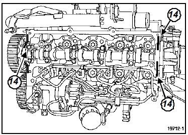
- Apply beads (14) of SILICONE 77 11 219 706, 2 mm in diameter.
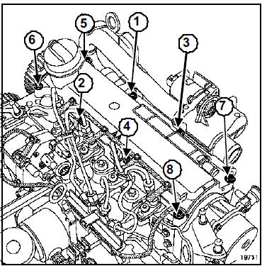
- Refit the rocker cover.
- Tighten the rocker cover mounting bolts in sequence to the specified torque (1 daN.m).
- Reconnect the turbocharger oil return pipe, fitted with new seals.
- Tighten the turbocharger oil return pipe to torque (0.9 daN.m).
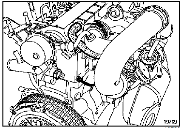
- Reconnect:
- the oil vapour breather hose,
- the new turbocharger air sleeves.
- Refit in the reverse order of removal.
- Refit the catalytic converter (see Exhaust chapter).
- Refit the timing belt (Front of Engine chapter, Timing Belt, page 11A-5).
- Refit the accessory drive belt (Front of Engine chapter, Accessory Drive Belt, page 11A-1).
- Fill and bleed the cooling system (see Section Cooling).
- Prime the diesel fuel circuit (see Fuel Supply chapter).
Connect the battery; carry out the necessary re-learns (see Electrical Equipment chapter).
F9Q
Essential special tools |
|
| Mot. 1202-01 | Spring clamp pliers (large model) |
| Mot. 1202-02 | Spring clamp pliers (small model) |
| Mot. 1367-02 | Engine support |
Essential equipment |
| cylinder head test tools |
| angle-torque wrench |
Before any work
- connect the diagnostic tool (aftermarket),
- communicate with the injection ECU,
- check that the injection rail is no longer pressurised,
- beware of the fuel temperature,
- order the special high-pressure injection circuit plug kit.
REMOVAL
- Position the vehicle on a two-post lift.
- Remove:
- the engine covers,
- the engine undertray.
- Disconnect the battery.
- Drain the cooling system through the lower radiator hose using tool (Mot. 1202-01) or (Mot. 1202-02).
- Fit plugs to the openings.
- Strictly observe all safety instructions.
- See Diesel Injection chapter, page .
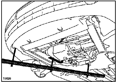
- Fit the engine support using tool (Mot. 1367-02).
- Remove:
- the auxiliary drive belt (Chapter Upper and front engine, Auxiliary drive belt, page 11A-1),
- the timing belt (Chapter Upper and Front Engine, Timing Belt, page 11A-5).
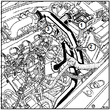
- Disconnect:
- the vacuum hose on the vacuum pump,
- the air hose (1),
- the air duct (2) on the turbocharger,
- the air duct (3) on the intake manifold.
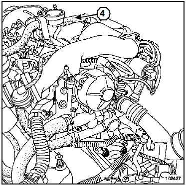
- Disconnect the oil vapour breather hose (4).
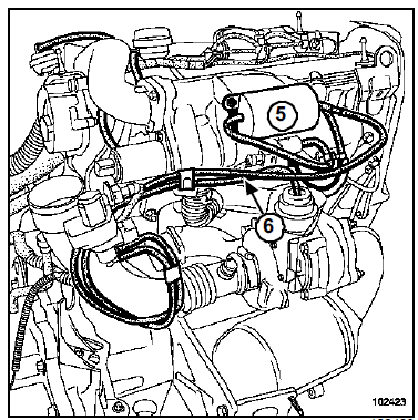
- Remove the vacuum reservoir mountings (5).
- Disconnect the vacuum hoses (6).
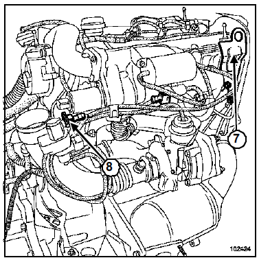
- Remove the engine lifting lug (7).
- Disconnect the connector (8).
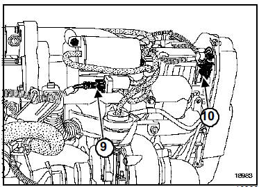
- Disconnect
- the exhaust gas recirculation solenoid valve connector (9),
- the camshaft sensor connector (10).
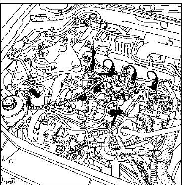
- Disconnect the connectors:
- the injectors,
- of the glow plugs,
- of the high-pressure injection pump,
- of the pressure sensor,
- of the pressure regulator,
- of the diesel return pressure sensor,
- of the diesel filter.
- Release the wiring.
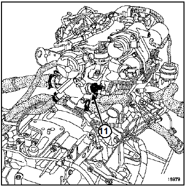
- Disconnect:
- the hoses from the cylinder head coolant outlet housing,
- the connector (11).
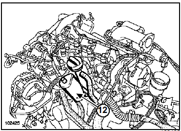
- Remove the oil vapour breather reservoir (12).
- Disconnect:
- the fuel return hose,
- the fuel supply hose.
- Fit the cleanliness plugs.
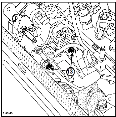
- Remove the rear mountings (13) of the high-pressure pump bracket.
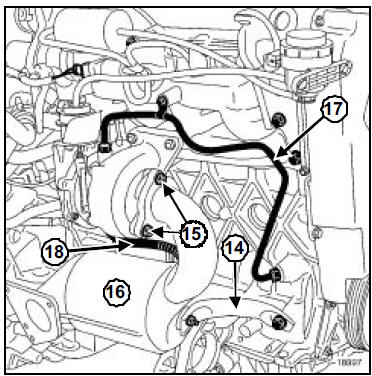
- Remove:
- the stand (14),
- the catalytic converter mountings (15),
- the catalytic converter (16).
- Disconnect:
- the oil supply pipe (17),
- the oil return pipe (18).
- Remove:
- the cylinder head bolts,
- the cylinder head.
I - CLEANING
Clean the cylinder head.
WARNING- Do not scrape the gasket surfaces of the aluminium parts.
- Wear gloves during the operation.
- Clean the mating surfaces with DÉCAPJOINT to dissolve the remaining gasket material stuck to the lower casing and the cylinder block.
- Apply the product to the area to be cleaned; wait approximately ten minutes, then remove the residue with a wooden spatula.
- Take particular care during this operation to prevent foreign matter from entering the oil galleries (galleries located in both the cylinder block and the cylinder head).
- Protect the oil feed duct to prevent foreign matter from entering the oil supply passages to the cylinder head.
- Failure to observe this instruction may block the oil supply passages and cause rapid damage to the camshaft.
The cylinder head bolts must be replaced after each removal and must not be oiled before fitting.
II - CHECKING THE GASKET SURFACE
- Check for distortion of the cylinder head mating face using a straightedge and feeler gauges.
The maximum distortion is 0.05 mm.
WARNING: No machining of the cylinder head is permitted.
- Pressure-test the cylinder head to detect any cracks, using the cylinder head test equipment (see Garage Equipment Catalogue).
- Refer to the Mot. F9 engine manual for the cylinder head removal procedure.
INSTALLATION
WARNINGBe sure to remove any oil present in the cylinder head bolt holes using a syringe.
- Refit in the reverse order of removal.
- Position the pistons at mid-stroke to avoid any risk of contact with the valves when tightening the cylinder head.
- Fit the cylinder head gasket.
- Refit the cylinder head.
- Tighten the cylinder head (see Powertrain Values and Settings chapter) using an angle-torque tightening wrench.
- Refit in the reverse order of removal.
WARNING: Be sure to replace all gaskets that have been removed.
- Refit the catalytic converter (see Exhaust chapter).
- Refit the timing belt (Front of Engine chapter, Timing Belt, page 11A-5).
- Refit the accessory drive belt (Front of Engine chapter, Accessory Drive Belt, page 11A-1).
- Fill and bleed the cooling system (see Section Cooling).
- Prime the diesel fuel circuit (see Fuel Supply chapter).
Connect the battery; carry out the necessary re-learns (see Electrical Equipment chapter).
F4R
Essential special tools |
|
| Mot. 1202-01 | Spring clamp pliers (large model) |
| Mot. 1202-02 | Spring clamp pliers (small model) |
| Mot. 1367-02 | Engine support |
| Mot. 1509-01 | Adapter kit for Mot. 1509 tool |
| Mot. 1632 | Camshaft seal fitting tool |
| Mot. 1512 | Camshaft seal fitting tool (28 x 47) |
| Mot. 1487 | Camshaft cover refitting tool |
| Mot. 1488 | Camshaft covers refitting tool |
Essential equipment |
| cylinder head test tools |
| angle-torque wrench |
Tightening torques |
|
| the nuts (3) | 8 daN.m |
| camshaft bearing cap bolts | 1.2 daN.m |
| New or original oil separator mounting bolts (in a threaded housing) | 1 daN.m |
| New oil separator mounting bolts (in an unthreaded housing) | 1.5 daN.m |
| Coils | 1.3 daN.m |
| Intake manifold | 0.9 daN.m |

REMOVAL
- Position the vehicle on a two-post lift.
- Remove the engine covers.
- Disconnect the battery.
- Drain the cooling system through the lower radiator hose using tool (Mot. 1202-01) and tool (Mot. 1202-02).
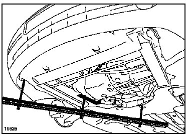
- Fit the engine support using tool (Mot. 1367-02).
- Remove the auxiliary drive belt (Chapter Upper and front engine, Auxiliary drive belt, page 11A-1).
- Remove the timing belt (Chapter Upper and Front Engine, Timing Belt, page 11A-5).
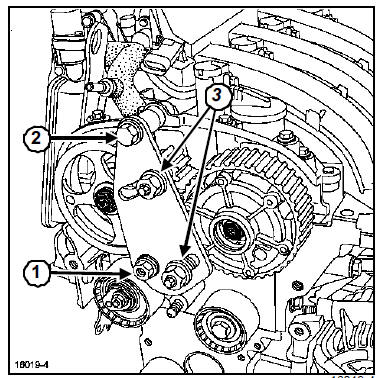
- Tighten the shouldered nut (1) and the bolt (2), then bring the tool (Mot. 1509-01) sprockets into contact with the camshaft pulleys while tightening the nuts (3) to torque (8 daN.m).
- Remove the intake camshaft phaser cap using a 14 mm hex key.
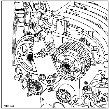
- Remove:
- the exhaust camshaft pulley nut,
- the intake camshaft phaser bolt.
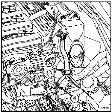
- Remove the mounting bolt of the bracket (4) and move it aside.
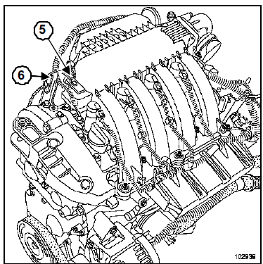
- Disconnect:
- the ignition coil connectors,
- the air temperature sensor connector (5),
- the variable valve timing connector,
- the oxygen sensor connector of the catalytic converter.
- Remove
- the ignition coils,
- the brake booster vacuum hose from the intake manifold,
- the variable valve timing solenoid valve,
- the engine lifting bracket (6) on the timing side,
- the air distributor.
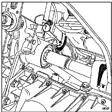
- Remove:
- the stand (7),
- the exhaust downpipe mountings.
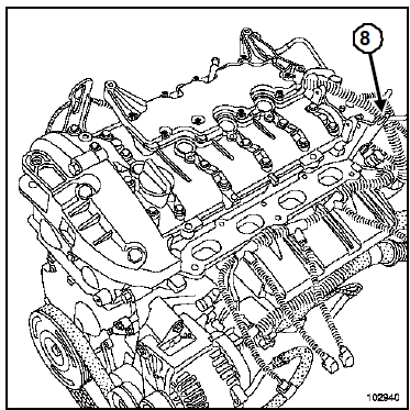
- Remove:
- the oil separator,
- the engine lifting bracket on the flywheel side (8).
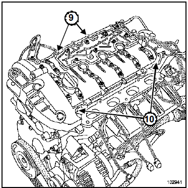
- Remove the camshaft bearing cap bolts, then lift the cap off vertically by tapping on the "lugs" (9) with a bronze drift, and lever it with a screwdriver (10) (protect the screwdriver to avoid damaging the aluminium surfaces).
- Remove:
- the camshafts,
- the rocker arms.
- Disconnect the hoses from the cylinder head coolant housing.
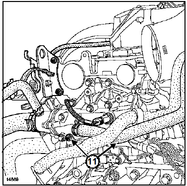
- Disconnect
- the coolant temperature sensor connector,
- the wiring harness bracket mountings at (11).
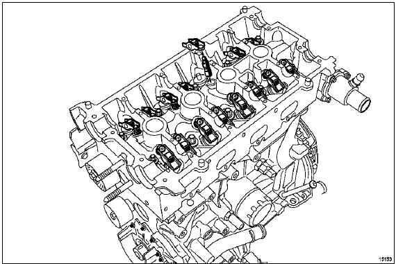
- Remove the cylinder head.
I - CLEANING
WARNING- Do not scrape the mating surfaces of aluminium parts.
- Wear safety glasses.
- Wear gloves during the operation.
- Clean the mating surfaces with DECAPJOINT product to dissolve the part of the gasket remaining stuck.
- Apply the product to the area to be cleaned; wait approximately ten minutes, then remove it using a wooden spatula.
- Take great care with this operation to prevent foreign bodies from entering the oil passages (passages located in the cylinder block and in the cylinder head).
II - CHECKING THE MATING SURFACE
- Check with a straightedge and a set of feeler gauges whether the mating surface is distorted.
Maximum distortion: 0.05 mm
CAUTION No machining of the cylinder head is permitted.
- Pressure test the cylinder head to detect any cracks, using the cylinder head pressure test equipment (see Garage Equipment Catalogue).
- Set the pistons to mid-stroke to prevent contact with the valves when refitting the camshafts.
- Fit the cylinder head gasket.
INSTALLATION
- Refit the cylinder head.
- Check the bolts.
- Tighten the cylinder head (see Cylinder head tightening) using an angle-torque wrench.
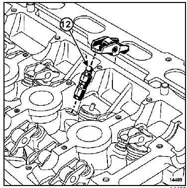
- Bleed the hydraulic lash adjusters, as they may drain if left for too long.
To check or bleed them, press the top of the adjuster at (12) with your thumb. If the adjuster piston moves down, immerse it in a container filled with diesel, then reinstall it.
- Refit:
- the rocker arms,
- the camshafts, lubricating the bearings with oil.
Do not apply oil to the mating surface of the camshaft bearing cap housing.
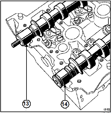
- The camshafts are identified by their pulley mountings.
Pulley mounting details:
- (13): exhaust camshaft,
- (14): intake camshaft.
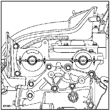
- Position the camshaft slots as shown in the illustration.
- The mating surfaces must be clean, dry and free of grease.
- Excess sealant applied may overflow when the parts are tightened. Mixing the sealant with the coolant may damage certain components (engine, radiator).
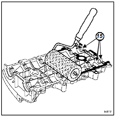
- Apply LOCTITE 518 to the camshaft bearing housing mating surface with a foam roller until the surface turns reddish.
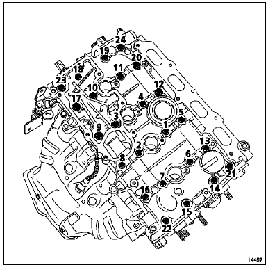
- Refit the camshaft bearing housing.
- Tighten the camshaft bearing cap bolts in sequence and to torque: 22, 23, 20, 13 (0.8 daN.m).
- Tighten the camshaft bearing cap bolts in sequence and to torque (1.2 daN.m):
- 1 to 12,
- 14 to 19,
- 21 and 24.
- Loosen bolts 22, 23, 20, 13 in sequence.
- Tighten the camshaft bearing cap bolts in sequence and to torque: 22, 23, 20, 13 (1.2 daN.m).
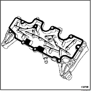
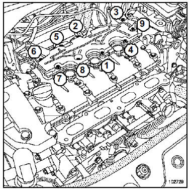
- The mating surfaces must be clean, dry and free of grease.
- Excess sealant applied may overflow when the parts are tightened. Mixing the sealant with the coolant may damage certain components (engine, radiator).
- Apply LOCTITE 518 to the oil separator mating surface with a foam roller until it turns reddish.
- Tighten in sequence and to torque:
- New or original oil separator mounting bolts (in a threaded hole) (1 daN.m),
- New oil separator mounting bolts (in an unthreaded hole) (1.5 daN.m).
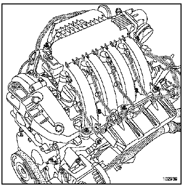
- Refit the ignition coils.
- Tighten the ignition coils to torque (1.3 daN.m).
- Refit the intake manifold (fitted with new gaskets).
- Tighten the intake manifold in sequence and to torque (0.9 daN.m).
- Refit the camshaft phaser solenoid valve and its new seal.
Replacing the camshaft seals:
- use tool (Mot. 1632) for the intake camshaft seal,
- use tool (Mot. 1512) for the exhaust camshaft seal.
- Refit:
- the timing belt (the method must be strictly followed (Chapter Upper and Front Engine, Timing Belt, page 11A-5),
- the accessory belt (Chapter Upper and Front Engine, Accessory Belt, page 11A-1).
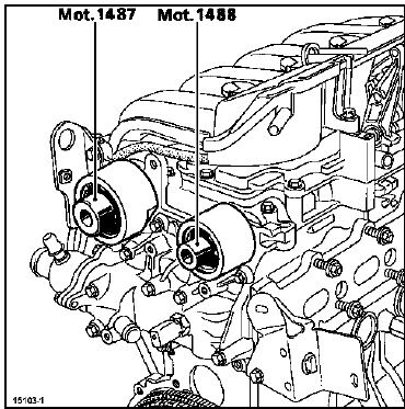
- Refit:
- the throttle body,
- new sealing plugs:
- of the intake camshaft (Mot. 1487),
- of the exhaust camshaft (Mot. 1488),
- the right-hand pendulum mount (Chapter Engine Mounting, Pendulum Mount Setting Values, page 19D-1).
- Refit in the reverse order of removal.
- Fill and bleed the cooling system (Chapter Cooling, Cooling System Draining - Filling, page 19A-2).
Connect the battery; carry out the necessary relearn procedures (Chapter Battery).
Test yourself
A quick Renault Megane quiz: every answer comes with an explanation and a link to the manual page.