Diagnostic innovations
Special notes
Warning: the MEGANE II can only be diagnosed with the CLIP diagnostic tool fitted with the new vehicle link lead-probe (Reference: Elé. 1674 or 00 00 167 400).Introduction:
The purpose of this "Diagnostic Innovations" chapter is to present the main diagnostic developments linked to changes in vehicle characteristics and in particular to the complexity of its architecture. These diagnostic developments are classified into four categories:
- Diagnostic procedure: this sub-chapter describes the overall diagnostic procedure to apply to the vehicle, as well as the changes related to the diagnostic tool.
- New diagnostic tool application: this sub-chapter describes changes in how information is presented in Diagnosis and Repair modes.
- Control Module Diagnosis: this sub-chapter describes the different functions accessible in Diagnosis and Repair modes.
- Function Diagnosis: this sub-chapter describes the different functions accessible in Function Diagnosis mode (Keyless Vehicle, Air Conditioning and Tyre Pressure) and Repair.
1. Diagnostic Procedure:
1.1. Control Module Power Supply:
To diagnose the vehicle control modules, the ignition must be placed in Diagnosis mode (+ after ignition), i.e. proceed as follows:
- Vehicle badge on badge holder (Keyless vehicle scenarios 1 (entry level, without hands-free) and 2 (high end, with hands-free)).
- Press and hold the "start" button (more than 5 seconds) outside starting conditions.
- Then connect the diagnostic tool and carry out the required operations.
Important: the left and right Xenon lamp control modules are powered when the dipped beam headlamps are switched on. Their diagnosis is therefore only possible after switching the ignition to Diagnosis mode and switching on the dipped beam headlamps.
To switch off the +after ignition, proceed as follows:
- Disconnect the diagnostic tool.
- Briefly press the "start" button twice.
- Check that the +after ignition forced is switched off by the computer warning lights on the instrument panel going out.
1.2 Diagnostic Procedure:
The diagnostic procedure applicable to the Mégane vehicle is as follows:
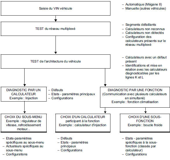
- Vehicle identification by entering the vehicle VIN: this new function identifies the vehicle precisely. It notably provides the operator with the aftersales type, engine type and gearbox type of the vehicle.
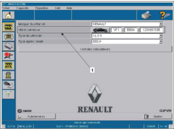
Screenshot given as an example: not representative of the actual vehicle architecture.
Key:VIN entry: the VIN can be entered in automatic mode (the diagnostic tool queries the vehicle and suggests the vehicle VIN, aftersales type, engine type, etc.) or in manual mode (the operator enters the vehicle VIN manually and the tool displays the detailed vehicle characteristics).
- Multiplexed Network test: this diagnostic step is mandatory before accessing the diagnosis and repair of a control unit or function. It includes a Multiplexed Network test (completed by an identification and a reading of the number of control unit faults) as well as a connection and identification of the K-L line diagnosable control units present on the vehicle.
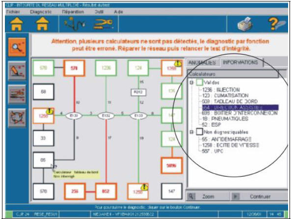
"Screenshot provided as an example only: not representative of the actual vehicle architecture".
This diagram shows the result of the Multiplexed Network test and the faults associated with the control units.
Examples contained in the circled area:Valid:
1236: Injection
120: Air conditioning
589: Instrument panel
654: Power steering
698: Interconnection box
18: Tyres
52: ESP
Not diagnosable:
55: Immobiliser
1258: Gearbox
587: UPC
(Diagnosis by function is also accessible from the following screen:)
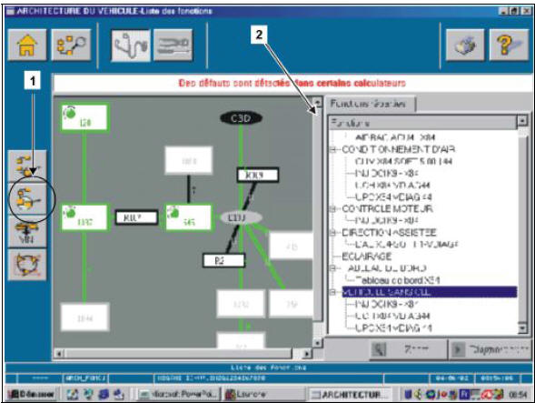
"Screenshot provided as an example only: not representative of the actual vehicle architecture".
Key:- Access menu for the vehicle functions list
- Vehicle functions list: this menu shows the operator the accessible vehicle functions as well as the various control units contributing to the function (the graphical result is visible on the diagram representing the vehicle's multiplexed network):
Examples in this area:
- Air conditioning:
- ["Clim X84 SOFT 5.00 $44"]: air conditioning control unit.
- ["INJ DCI K9 X-84"]: injection control unit.
- ["UCH X84 VDIAG 44"]: Passenger compartment central unit (UCH).
- ["UPC X84 VDIAG 44"]: Power and switching unit (UPC).
- Engine management:
- ["INJ DCI K9-X84''] : Injection control unit.
- Power steering:
- ["DAE X84-SOFT1-VDIAG''] : Power steering control unit.
- Lighting
- Instrument panel:
- ["Tableau de bord X84"]: Instrument panel control unit.
- Keyless vehicle:
- ["INJ DCI K9-X84"]: Injection control unit.
- ["UCH X84 VDIAG 44"]: Passenger compartment central unit (UCH).
- ["UPC X84 VDIAG 44"]: Power and switching unit (UPC).
- Vehicle architecture: this function is the overall result of the vehicle integrity test performed previously.
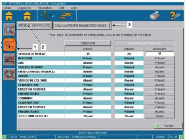
"Screenshot provided as an example only: not representative of the actual vehicle architecture".
Key:- Access menu for the vehicle electronic architecture
- Multiplexed Network control unit configuration:
This configuration defines the control units present on the vehicle's Multiplexed Network. It must be performed when replacing the airbag control unit or the Passenger Compartment Central Unit (UCH).
- Diagnosable control unit configuration:
Diagnosable control unit configuration is a new vehicle function. It is mandatory in order to define the diagnosable control units with the Renault diagnostic tool. It allows the determination of non-compliance or non-response of a vehicle control unit.
The diagnosable control unit configuration of the vehicle is stored in the Passenger Compartment Central Unit (UCH) and the airbag control unit. It is specific to the vehicle being diagnosed and must be redefined when replacing either of these two control units.
During the diagnosable control unit configuration, the tool displays the list of control units defined in the other control unit as an aid and support for the operator.
Finally, if in doubt about the vehicle's diagnosable control units, the complete list (specific to the vehicle) can be obtained by consulting the World Vehicle Database (BVM).
- Diagnosis by control unit: after the vehicle architecture result, the diagnostic tool dynamically lists the various control units accessible for diagnosis and repair with the Renault tool. Diagnosis by control unit provides access to all functions related to processing and repairing a fault.
- Diagnosis by function: after the vehicle architecture result, the diagnostic tool dynamically lists the various functions accessible with the Renault tool. In addition, selecting a function dynamically identifies the control units responsible for that function. Diagnosis by function provides simultaneous diagnosis of the control units involved in a given function, as well as the configurations related to that function.
Warning: not all menus of the "Repair" mode described above are accessible in Diagnosis by function. Indeed, a function is diagnosed, and a part or a control unit is repaired.
Example: when selecting the "Keyless Vehicle" function, the UCH (Passenger Compartment Central Unit), UPC (Power and Switching Unit) and Injection control units appear graphically on the vehicle architecture result screen.
REMINDER:The Renault diagnostic procedure still applies to Mégane II. As a reminder, faults (by control unit or by function diagnosis) are dealt with first. If the customer complaint is not resolved, then perform a compliance check (either by control unit or by function) and finally, a diagnosis by "customer effect".
IMPORTANT:In the diagnostic tool's functions, Mégane II distinguishes between diagnosis (identifying and resolving the customer complaint) and repair (modifying the characteristics of a control unit after identifying the cause of the problem, or replacing a part or the control unit).
2. Presentation of the new general navigation of the Diagnostic tool:
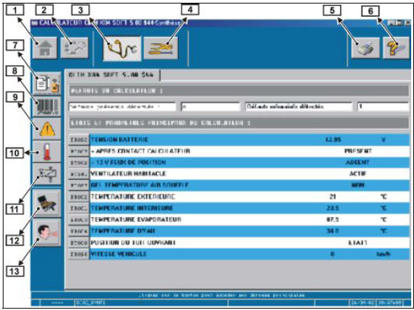
"Screenshot provided as an example only: not representative of the actual vehicle architecture".
IMPORTANT:Navigation and menu selection in the diagnostic tool are now performed with the mouse, then a function is confirmed by pressing the left mouse button.
Key:- Home menu: allows selection and performance of the global vehicle identification (using the VIN) of the vehicle being diagnosed.
- Previous screen: returns to the previous step.
- Diagnostic mode: used to select the diagnostic mode (here, air conditioning panel) and to access the various menus of the selected mode.
- Repair mode: used to access repair mode. This new mode groups together the functions "Configuration Read-Write", "Other Settings", "Learning" and "Erasing". All menus are only accessible in control unit diagnosis.
- Print: used to print the data displayed on screen.
- Help: used to access the help menu of the diagnostic tool.
- Main Data: used to access the summary screen in control unit diagnosis or function diagnosis.
- Identification: used to access the identification screen in control unit diagnosis or function diagnosis.
- Fault Check: used to access the fault screen in control unit diagnosis or function diagnosis.
- Status / Parameter Reading: used to access the status and parameter screen in control unit diagnosis or function diagnosis.
Note: this new screen groups together the statuses and parameters defined for a control unit, which previously appeared in the separate "Status" and "Parameter" menus.
- Actuators: used to access the actuators in control unit diagnosis or function diagnosis.
- Conformity Check: used to access the conformity check in control unit diagnosis only.
- Customer Effect Test: used to access the customer effect test in control unit diagnosis only.
3. Control Unit Diagnosis - Repair:
3.1. Control Unit Diagnosis:
This chapter covers the new screens and functions linked to the evolution of the diagnostic tool in control unit diagnosis mode. The "Diagnosis" section must also be distinguished from the "Repair" section.
3.1.1. Summary Screen:
This is the first screen accessible after selecting the "Control Unit Diagnosis" mode and the control unit to be diagnosed.
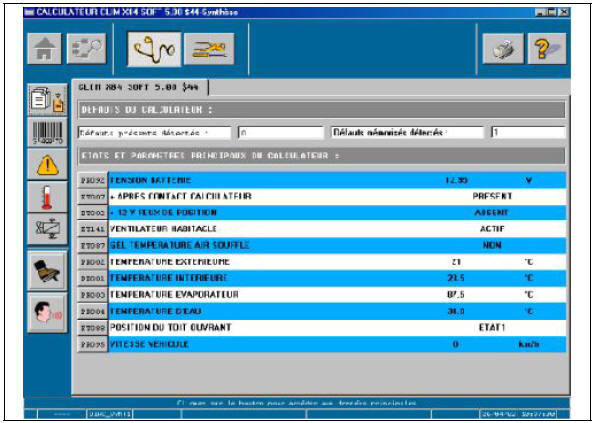
"Screenshot provided as an example only: not representative of the actual vehicle architecture".
This new screen provides a summary of the operating elements of the diagnosed control unit. It includes a summary of the present and stored faults of the control unit (number of faults recorded in the control unit memory) as well as the main statuses and parameters of the control unit. This screen therefore gives an overall view of the control unit's operation.
3.1.2. Identification Screen:
The main new feature of this identification screen is the formatting of the control unit identification information.
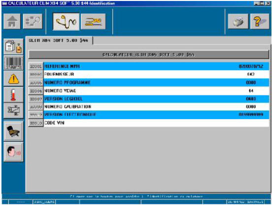
"Screenshot provided as an example only: not representative of the actual vehicle architecture".
3.1.3. Fault Screen:
The main new feature of this screen is direct access to the function for erasing stored faults (callout 1).
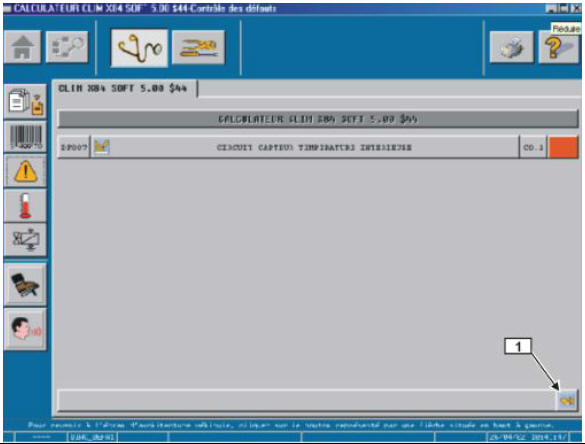
"Screenshot provided as an example only: not representative of the actual vehicle architecture".
Key:- Erasing stored faults: this function allows stored faults to be erased directly.
REMINDER:
- A "left mouse click" on the fault label (here, interior temperature sensor circuit) opens the fault context screen. Depending on the capabilities of the diagnosed control unit, this screen displays the current and stored values of the statuses and parameters recorded when the fault appeared.
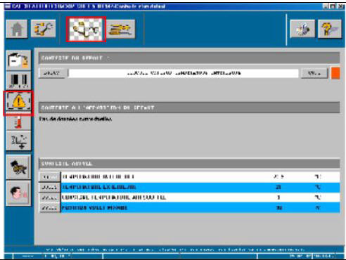
"Screenshot provided as an example only: not representative of the actual vehicle architecture".
- A "mouse click" on the fault index (here, DF007) or the fault characterization (here, CO.1) opens the help screen.
- To return to the Fault screen, press the "previous screen" key or the "Fault" key.
3.1.4. Status and Parameter Screen:
This screen displays the statuses and parameters required for the conformity check of the diagnosed control unit. These statuses and parameters are sorted by sub-function (here, user selection - cold loop - cabin ventilation and heating - see callout 1) to simplify monitoring by the operator.
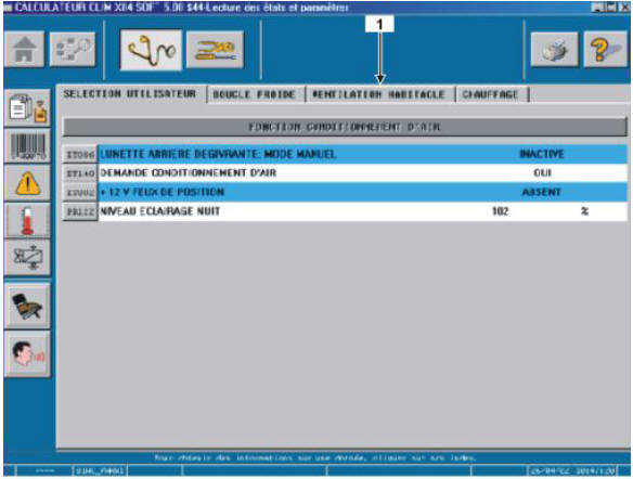
"Screenshot provided as an example only: not representative of the actual vehicle architecture".
Legend: Zone 1: access to the parameter help screen.
A "mouse click" on the index of the status or parameter (for example, PR122) opens the parameter help screen to make its analysis and processing easier:
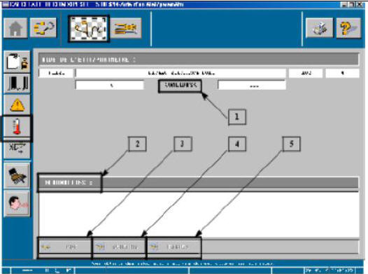
"Screenshot provided as an example only: not representative of the actual vehicle architecture".
This help screen contains the items shown on the previous screen (index, parameter label, instantaneous value) as well as new functions:
Key:- Values: this field gives the limit values of the parameter under normal control unit operating conditions.
- Information: this field describes the parameter and specifies the vehicle operating conditions for which the specified limit values are representative.
- PDF: a "mouse press" on this button opens the processing and interpretation of the parameter described in the technical note applicable to the control unit.
- Diagrams: a "mouse press" on this button displays the wiring diagram of the component linked to the monitored parameter.
- Sheets: a mouse press on this button opens the sheet of the component linked to the parameter in order to carry out the conformity checks.
To return to the Status - Parameters screen, press the "previous screen" key or the "Status - Parameter Reading" key.
3.1.5. Actuators Screen:
This screen gives access to the actuator commands of the diagnosed control unit. These actuator commands are sorted by sub-function (here, cabin ventilation and heating) to simplify the operator's search.
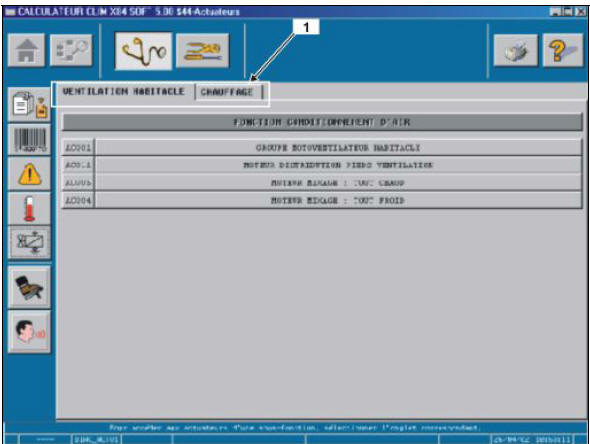
"Screenshot provided as an example only: not representative of the actual vehicle architecture".
Key:- Zone 1: a "mouse click" in zone 1 opens the specific actuator command screen.
Actuator command:
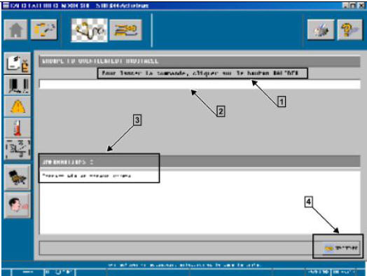
"Screenshot provided as an example only: not representative of the actual vehicle architecture".
This actuator command screen shows the actuator label (here, cabin blower motor group) as well as new functions:
Key:- "Instructions": this field indicates the procedure to follow to start the actuator command.
- "Progress": this field shows the progress of the command. Messages are of the type "command in progress" - "command completed".
- "Information": this field specifies the vehicle operating conditions under which the actuator command can be performed.
- "Confirm": a mouse press on this button starts the actuator command.
To return to the actuator commands screen, press the "previous screen" key or the "Actuator" key.
3.2. Control Unit Repair:
This chapter covers the new screens and functions related to the evolution of the diagnostic tool in "ECU repair" mode.
The "ECU Repair" mode is accessed after selecting the ECU and pressing the "Repair" key on the Diagnostic tool. It allows you to perform the operations "Configuration Read - Write", "Other Settings", "Learning" and "Erasing".
3.2.1. Configuration Read:
This function allows you to check the configurations of an ECU before replacing a component, replacing the ECU, or after modifying the ECU functions.
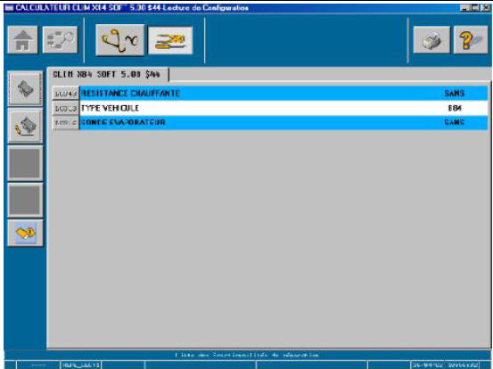
"Screenshot provided as an example only: not representative of the actual vehicle architecture".
3.2.2. Configuration Write:
This function allows you to modify the configurations of an ECU after replacing a component, replacing the ECU, or after modifying the ECU functions.
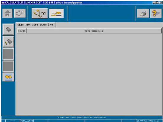
"Screenshot provided as an example only: not representative of the actual vehicle architecture".
This screen shows all the configurations relating to the diagnosed ECU. To perform a configuration, click the configuration label with the mouse to go to the next screen.
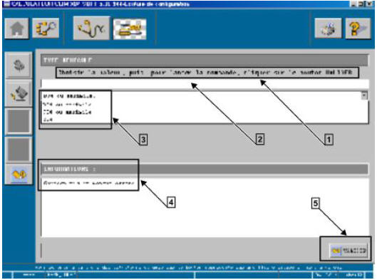
"Screenshot provided as an example only: not representative of the actual vehicle architecture".
This ECU configuration screen shows the configuration label (here, vehicle type) as well as new functions:
Key:- "Instructions": this field indicates the procedure to follow in order to start the configuration.
- "Progress": this field shows the progress of the configuration. Messages are of the type "command in progress" - "command completed".
- "Setting": this field defines the parameter to be written to the ECU memory in order to perform the configuration (here, B84 or equivalent, J84 or equivalent...).
- "Information": this field specifies the vehicle operating conditions under which the configuration can be performed.
- "Validate": a mouse click on this button starts the configuration.
To return to the configuration write screen, press the "previous screen" key or the "Configuration Write" key.
3.2.3. Other Settings:
This function groups together all the configuration-learning procedures of an ECU (example: configuration of a Cabin Central Unit, assignment of badges). The procedures are specific to each ECU, so they are not described in this chapter but in the chapters relating to ECU diagnosis and repair.
3.2.4. Learning:
This function groups together all the procedures relating to the replacement of a part requiring that this part be paired with the vehicle (example: throttle body, whose mechanical stops must be learned). These learning procedures are specific to an ECU, so they are described in the specific ECU chapters.
3.2.5. Erasing:
This function groups together the various erasing operations defined for an ECU. Examples include erasing faults (all ECUs) and erasing learned values (injection ECU, for example).
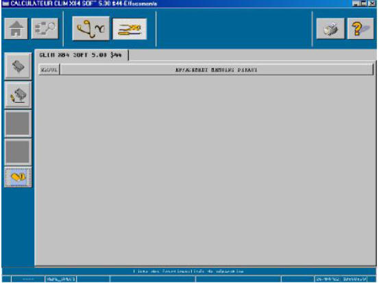
"Screenshot provided as an example only: not representative of the actual vehicle architecture".
This screen shows the various erasing operations defined for a given ECU. The erasing function is accessed by clicking the erasing label with the mouse (here, erase fault memory).
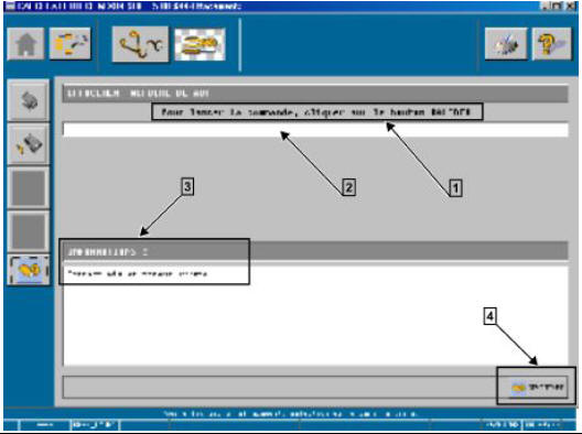
"Screenshot provided as an example only: not representative of the actual vehicle architecture".
This erasing screen shows the erasing label (here, erase fault memory) as well as new functions:
Key:- "Instructions": this field indicates the procedure to follow in order to start the configuration.
- "Progress": this field shows the progress of the configuration. Messages are of the type "command in progress" - "command completed".
- "Information": this field specifies the vehicle operating conditions under which the actuator command can be performed.
- "Validate": a mouse click on this button starts the actuator command.
To return to the erasing screen, press the "previous screen" key or the "Erasing" key.
4. Diagnosis - Function Repair:
This new diagnosis and repair mode is linked to the increasing complexity of the vehicle architecture and to the distribution of a customer function across several "independent" ECUs. This type of diagnosis allows simultaneous communication with the different ECUs performing a given function.
4.1. Function Diagnosis:
This sub-chapter describes the particularities of this diagnosis mode compared with the ECU diagnosis described previously.
4.1.1. Summary Screen:
The main change compared with ECU diagnosis is the presence of tabs giving access to the summary screens of the different ECUs of a given function (here, the "air conditioning" function grouping the air conditioning, injection, Cabin Central Unit and Protection and Switching Unit ECUs / see item 1). All other elements are strictly identical to ECU diagnosis.
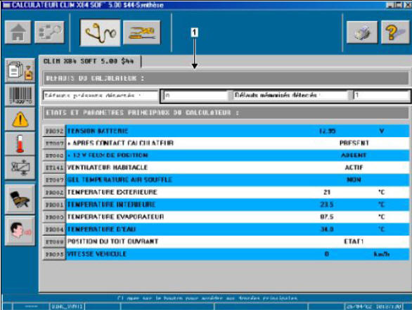
"Screen copy given as an example: not representative of the actual vehicle architecture"
Key:- Zone 1: a mouse click in zone 1 gives access to the specific screen of the desired function.
4.1.2. Identification Screen:
Same remarks as in the previous chapter.
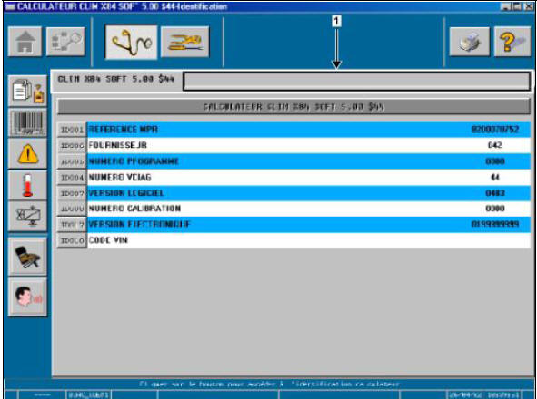
"Screenshot provided as an example only: not representative of the actual vehicle architecture".
Key:- Zone 1: a mouse click in zone 1 gives access to the specific screen of the desired function.
4.1.3. Fault Screen:
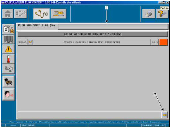
"Screenshot provided as an example only: not representative of the actual vehicle architecture".
Key:- Zone 1: a mouse click in zone 1 gives access to the specific screen of the desired function.
- Erasing stored faults: this function allows stored faults to be erased directly.
4.1.4. Status and Parameter Screen:
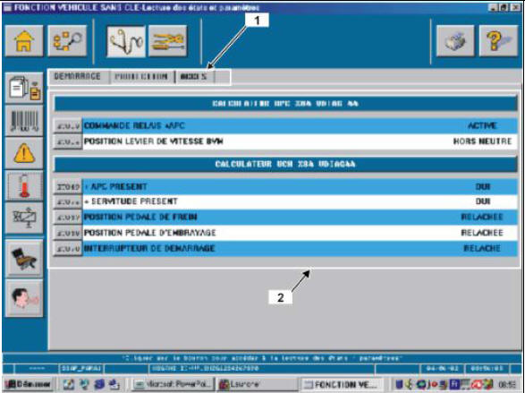
"Screenshot provided as an example only: not representative of the actual vehicle architecture".
Key:- Zone 1: list of the sub-functions associated with the selected function.
- Zone 2: list of the statuses and parameters associated with a sub-function, sorted by ECU. In function diagnosis, the statuses and parameters of a function (example: vehicle without key) are accessed by sub-function (example: starting) and then by ECU (example: UPC X84) in order to display the required information simultaneously.
4.1.5. Actuator Screen:
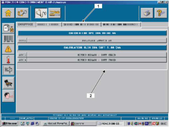
"Screenshot provided as an example only: not representative of the actual vehicle architecture".
Key:- Zone 1: list of the functions associated with the selected function.
- Zone 2: list of the actuators associated with a sub-function, sorted by ECU.
In function diagnosis, the actuators are accessed by sub-function (example: heating), then by ECU (example: UPC X84), and finally by actuator type (example: rear window defrost).
In function diagnosis, the actuators are accessed by sub-function (example: heating), then by ECU (example: UPC X84), and finally by actuator type (example: rear window defrost).
4.2. Function Repair:
4.2.1. Configuration Read:
This screen is identical to the configuration read screen in ECU mode. The only difference is the presence of tabs allowing you to select the ECUs (taking part in the function) whose configurations you want to check.
4.2.2. Unavailable Functions:
The functions not accessible in "diagnosis by function" mode are as follows:
- Configuration writing
- Other settings
- Learning procedures
- Erasures other than fault memory
This choice is linked to the diagnostic approach, which distinguishes the physical components from the functions they perform.
Test yourself
A quick Renault Megane quiz: every answer comes with an explanation and a link to the manual page.