Underbody structural repair
PARTS WITH MECHANICAL MOUNTING POINTS THAT REQUIRE SETTING ON THE JIG
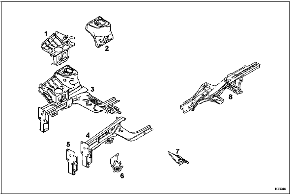
- Engine mount
- Front wheel arch
- Front half-assembly
- Front side member
- Radiator crossmember bracket
- Front subframe front mounting box
- Front subframe rear mounting box
- Rear side member
1. MAIN SETTING-UP REFERENCES
A - REAR FRONT SUBFRAME MOUNTING
This is the main front setting-up reference.
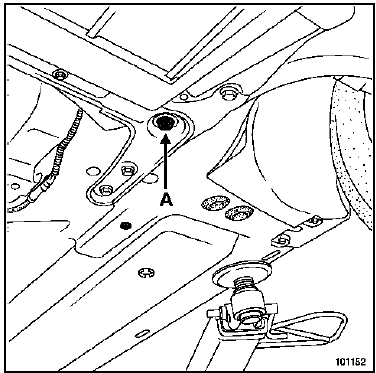
1 - Front mechanical unit in place
The gauge fits over the subframe mounting bolt.
Two cases may arise:
- - for a rear structural repair, these two points alone are sufficient for aligning and supporting the front of the vehicle.
- - for a minor front impact, without removing the front subframe.
If in doubt about deformation of one of the main reference points (A or B), it is nevertheless advisable to use two additional points located in an area not affected by the impact, in order to confirm the setting-up.
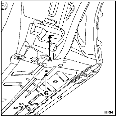
2 - Front mechanical unit removed
NOTE: On the left side the hole is round; on the right side it is a slot.
If the rear subframe bracket is replaced, this reference is temporarily replaced by point (G), located on the rear part of the front side member, with point (A) then used to position the replacement part.
IMPORTANT
This point helps ensure front suspension geometry. It aligns the front subframe with the body and has a direct influence on all front suspension angles.
B - REAR SUSPENSION FRONT MOUNTING
This is the main rear setting-up reference.
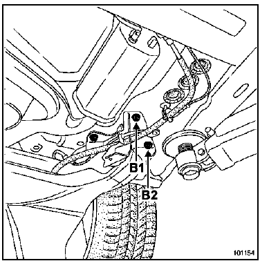
1 - Rear mechanical unit in place
The gauge fits over the rear suspension bearing bracket mounting bolts.
Used for a front impact or a minor rear impact.
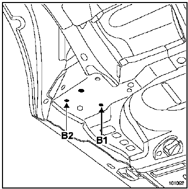
2 - Rear mechanical unit removed
The gauge rests under the rear suspension mounting box and is centred in the tapped holes of the rear suspension bearing bracket.
If the complete rear side member is replaced, this reference is replaced by point (G), located at the rear of the front side member, with point (B) then used to position the replacement part.
IMPORTANT
These points help ensure rear suspension alignment with the body and have a direct influence on the vehicle's tracking angle.
2. REFERENCES FOR POSITIONING REPLACED PARTS
C - FRONT SUBFRAME FRONT MOUNTING
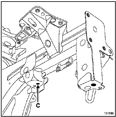
With only the front mechanical unit removed, the gauge rests under the front subframe front mounting box and is centred in the tapped subframe mounting hole. Use it when replacing:
- a partial or complete front side member,
- a front half-assembly.
IMPORTANT
This point helps ensure front suspension geometry. It has a direct influence on the vertical travel of the lower wishbone, and therefore on variations in castor and toe.
F - FRONT SHOCK ABSORBER UPPER MOUNTING
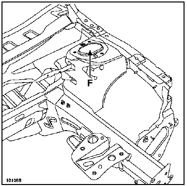
The gauge rests under the shock absorber top mount and is located in the shock absorber top mount hole.
Use it when replacing:
- a wheel arch section,
- a front half-assembly,
It is also used when straightening.
IMPORTANT
This point helps ensure front suspension geometry. It has a direct influence on steering axis inclination, camber and castor angles.
P - ENGINE MOUNTING
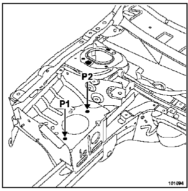
The gauge is placed over the engine mount and is centred in the mounting holes of the pad.
Use it with the mechanical unit removed when replacing:
- a front half-assembly,
- a front wheel arch.
H - FRONT SIDE MEMBER END
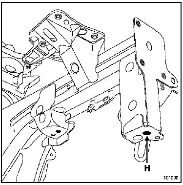
The gauge rests under the side member and is centred in the tapped hole of the radiator crossmember mounting.
Use it with the mechanical unit removed when replacing:
- a side member,
- a front half-assembly,
- a radiator crossmember bracket.
K - FRONT IMPACT CROSSMEMBER MOUNTINGS
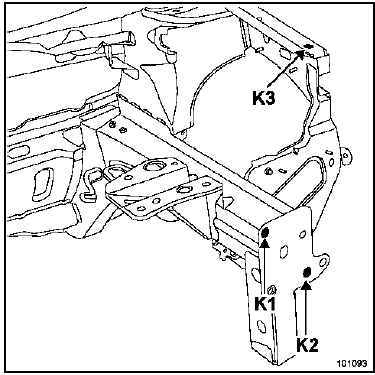
The gauge rests vertically against the radiator crossmember bracket and is centred in the tapped holes of the front impact crossmember mountings.
During structural repair, points (K1) and (K2) are used when replacing:
- a radiator crossmember bracket,
- a partial or complete front side member,
- a front half-assembly.
They also serve as a reference for the front wing upper support mounting point (K3).
J - REAR SIDE MEMBER END
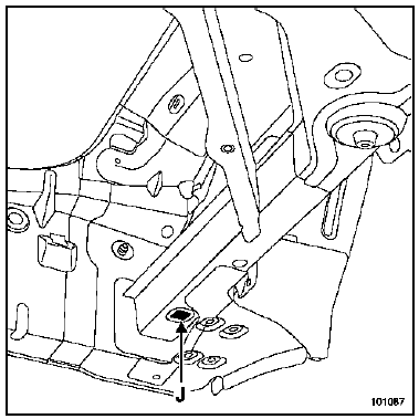
The gauge bears against the underside of the side member and is centred in the pilot hole.
Use with the body structure in place to realign the side member.
It is also used with the body structure removed, under the same conditions, when replacing the side member.
E - REAR SHOCK ABSORBER MOUNTING
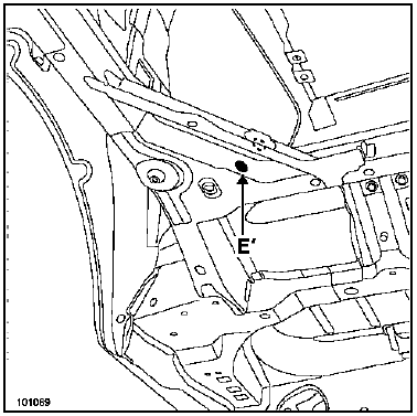
The gauge is centred and fixed on the shock absorber axis.
Use it when replacing:
- of the complete rear side member.
L - SILL PANEL CROSSMEMBER
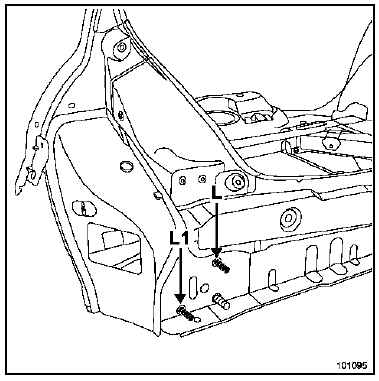
The gauge bears vertically against the rear sill panel lining and is centred on the studs for the rear bumper crossmember.
They are used when replacing:
- a bumper crossmember mounting reinforcement,
- a partial or complete rear side member.
BLACKHAWK
Specific heads for MS system
Order from: BLACKHAWK
Eurofret centre
Rue de Rheinfeld
67100 STRASBOURG
Supplier reference: REN-88 835
NOTE: These items are available on order only.
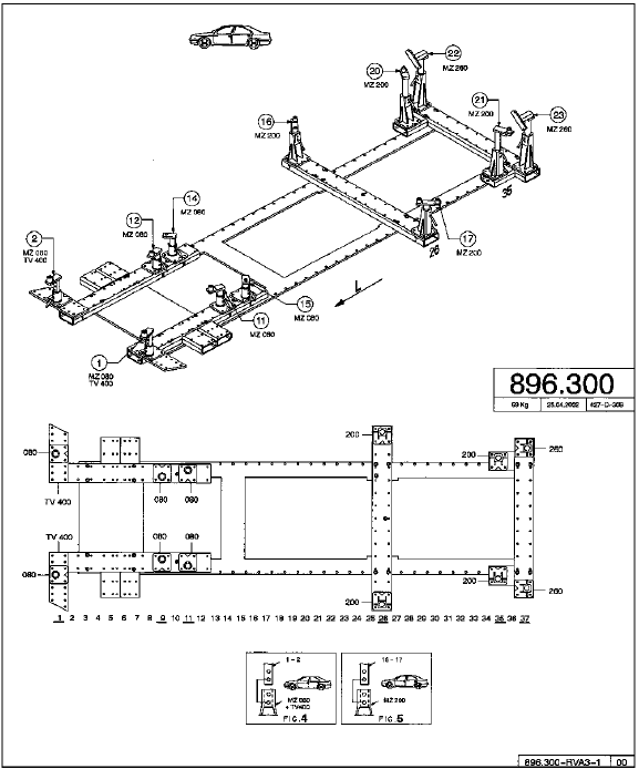
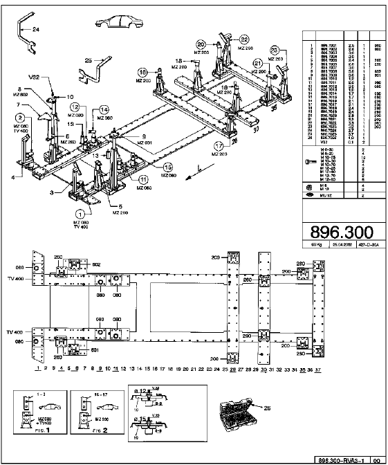
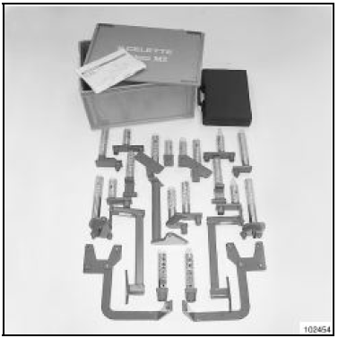
CELETTE
Specific heads for MZ system
Order from: CELETTE S.A
B.P.9
38026 VIENNE
Supplier reference: 896.300
ANCHORING KIT FOR CELETTE REPAIR BENCH
Supplier reference: AN.36
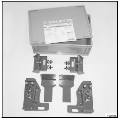
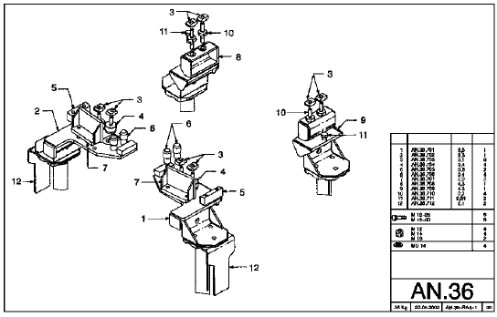
ANCHORING KIT FOR BLACKHAWK REPAIR BENCH
Supplier reference: AEK-186.4
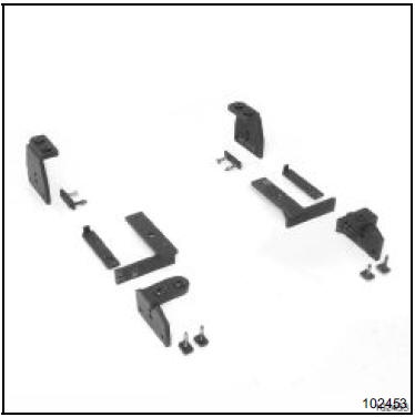
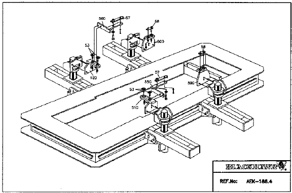
Test yourself
A quick Renault Megane quiz: every answer comes with an explanation and a link to the manual page.