Method symbols
The detailed explanations needed to understand the procedures are given below.
These are updated as required with each edition of the documents.
This means the most recently published repair manual is used as the reference.
1. Basic rules for replacing a structural component
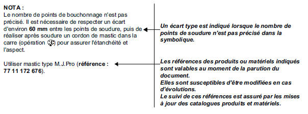
As a general rule, when replacing a welded body component, the repair must match the original in both number of spot welds and type of weld, for reasons of appearance and safety.
If, for practical repair reasons, this rule can only be partly met, the replacement solutions will be given in the repair procedures.
These solutions ensure mechanical strength complies with specifications and release the repairer from liability.
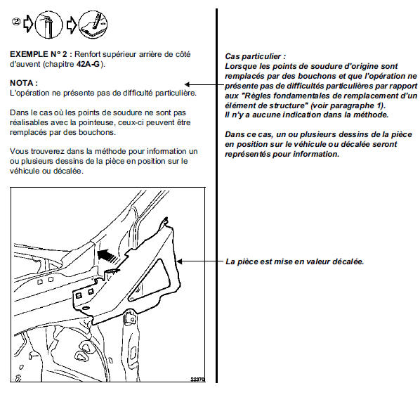
For this reason, the procedures only show welding details that differ from the original. Resistance spot welds are no longer shown on the diagrams.
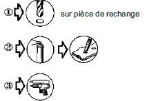
Most common cases for replacing a resistance spot weld:
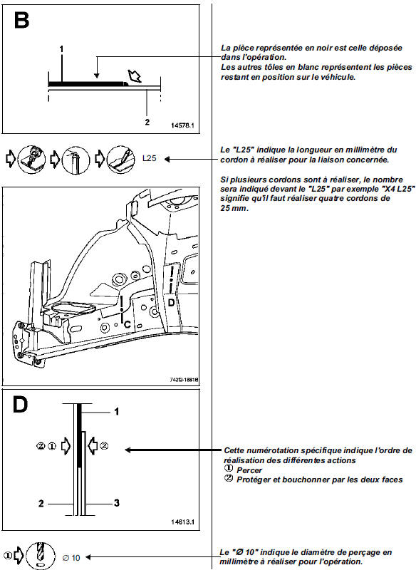
- Plug welding
- Seam welding
- Bonding
- Riveting
In some cases, the following will also be indicated:
- the tools and equipment used for the operations,
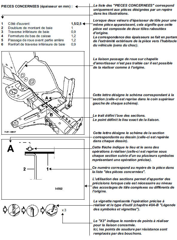
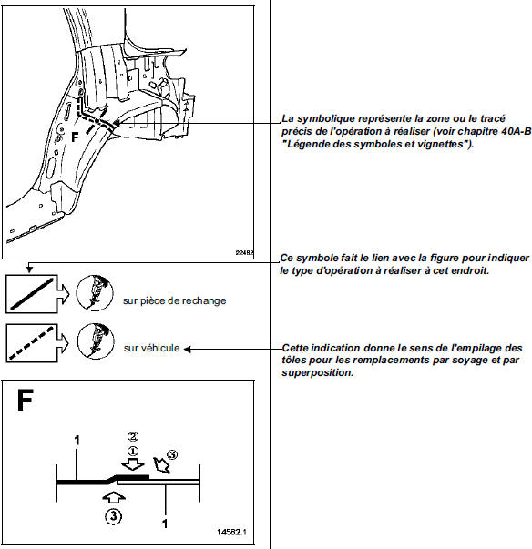
- the sections of particular sheet stacks that require explanation,
- the dimensions for positioning certain components,
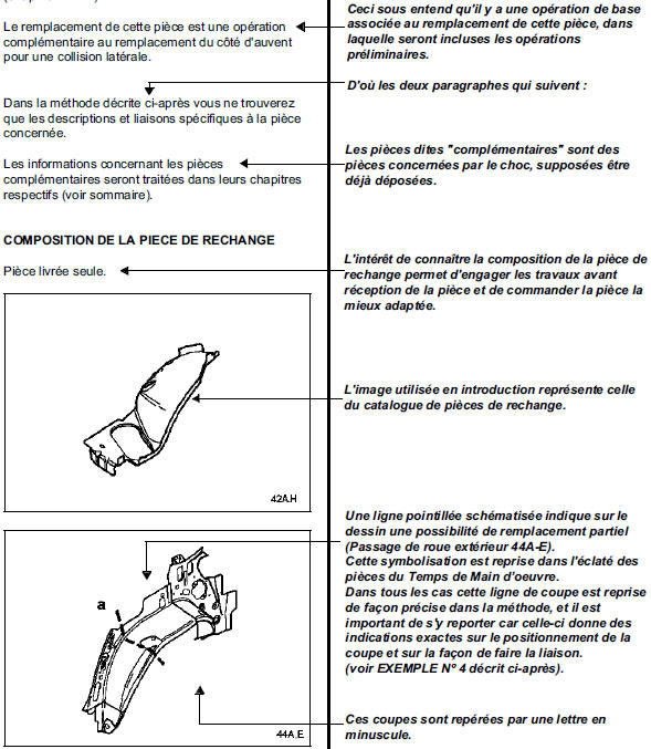
- the location of cut lines for partial replacements,
- the location of adhesive areas specific to the repair.
When a part is symmetrical (left and right sides identical), only one side is covered in the procedure (example: rear floor panel, rear section).
This means the opposite side is carried out using the same method (number of spot welds, etc.); otherwise, the differences are indicated.
Applies to left-hand and right-hand drive versions.
In this document, the diagrams best illustrate the replacement of the various parts for a typical impact described in each introduction.
The illustration must show the part to be replaced without the surrounding components, which are assumed to be already removed.
Some diagrams may nevertheless depart from this rule in order to show the part better in its surroundings.
Structural repair procedures are carried out on bare sheet metal bodies.
Original sealants are not shown.
Special features of replacements involving cuts: In general, the cut areas in the procedures are given for guidance only. They may be adjusted according to impact deformation, while observing the main safety rules described in the general section of the Bodywork Handbook.
Where the cut position is specified in the procedure, it must be followed.
IMPORTANT: The times for coded operations (TM) are based on the cut positions shown in the manual.
This means that if the operator chooses a different cut area, the allotted operation time will no longer apply.
2. Explanation of symbols
Several examples of representation for part replacement are given below, taken from the Vel Satis Repair Manual.
All explanations are shown in italics.
EXAMPLE NO. 1: Front wheel arch, front section (chapter 42A-H):
EXAMPLE NO. 3: Outer wheel arch (chapter 44A-E)
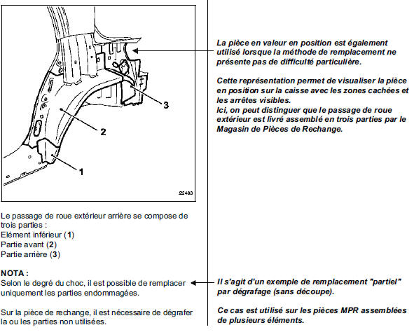
EXAMPLE NO. 4: Outer wheel arch, chapter 44A-E.
Test yourself
A quick Renault Megane quiz: every answer comes with an explanation and a link to the manual page.