Body Electrical System
Repair Procedures
In this manual: Body Electrical System
15steps
~90min
4/5difficulty
Done 0 of 15
Removal
- Disconnect the negative (-) battery terminal.
- Remove the steering wheel. (Refer to Steering System - "Steering Wheel")
- Remove the upper and lower steering column covers after loosening the screws. (Refer to Body - "Steering Column Cover Panel")
- Remove the clock spring. (Refer to Restraint System - "Driver Airbag (DAB) Module and Clock Spring")
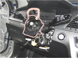
- Disconnect the multifunction switch connector (A).
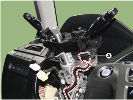
- Remove the multifunction switch assembly (A) after loosening the screws.
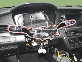
Installation
- Install the multifunction switch.
- Install the clock spring.
- Install the upper and lower steering column covers.
- Install the steering wheel.
Inspection
Multifunction Switch Inspection- Check the continuity between the terminals at each switch position according to the table.
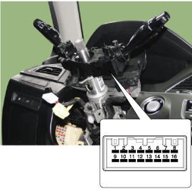
Switch Switch Position Switch Terminal Resistance (Ω, ±3.5%) Wiper Switch FOG 1-9 330 OFF ? Intermittent (AUTO) 800 LOW 1800 HIGH 5700 Intermittent Wiper Volume Level 1 7-9 330 Level 2 690 Level 3 1310 Level 4 2610 Level 5 7310 Fog Light Switch OFF 9-10 ? Front Fog Lamp 910 Turn Signal Switch OFF 9-12 ? Left 910 Right 2910 Dimmer and Headlight Switch OFF 9-13 ? Passing 910 Dimmer 2910 Switch OFF 9-14 ? AUTO / DRL 680 Rear Lamp 1680 Low Beam 5580 - Body electrical system malfunctioning parts can be quickly diagnosed using the Global Diagnostic System (GDS). The GDS provides the following information.
- Self-Diagnosis: Diagnostic Trouble Code (DTC) check and display
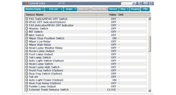
- Current Data: Check the system input/output status.
- Actuation Test: Check the system operating status
- Additional Functions: Other controls such as system option and zero point adjustment.
- Select "Vehicle Model" and the system to be checked to inspect the vehicle with the tester.
- Select "Body Control Module (BCM)" to inspect the multifunction switch.
- Select the "Current Data" menu to check the current input/output status. Input/output data for the sensors related to the multifunction switch can be checked.
Test yourself
A quick Hyundai Sonata LF quiz: every answer comes with an explanation and a link to the manual page.
Was this page helpful?