Body Electrical System
Smart Key Diagnostic Procedures
In this manual: Body Electrical System
32steps
~192min
4/5difficulty
Done 0 of 32
Inspection
Self-Diagnosis Using Scan Tool. The GDS can quickly diagnose SMART KEY system faults. The GDS can forcibly control actuators, perform input/output value monitoring and self-diagnosis. The following three functions are critical in the SMART KEY system.- SMART KEY Device Input Problem.
- SMART KEY Unit Problem.
- SMART KEY Device Output Problem.
- SMART KEY Unit Input Problem: Switch Diagnosis
- SMART KEY Unit Problem: Communication Diagnosis
- SMART KEY Unit Output Problem: Antenna and Switch Diagnosis
- Connect the GDS cable to the data link connector on the lower panel of the driver's side airbag, then turn on the GDS power.
- Select the vehicle model, then select the SMART KEY system.
- Select "Smart Key".
- After turning the IG on, select "Current Data".
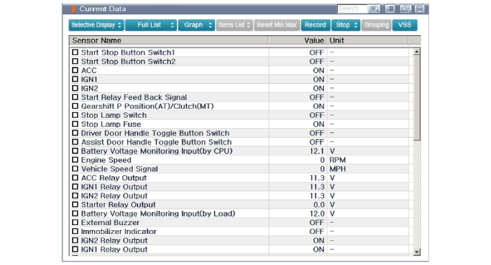
- You can check the status of each switch on the scan tool after connecting to the "Current Data" process.
Display Description FL Switch SW ON: The driver's door handle button is on. FR Switch SW ON: The auxiliary door handle button is on. Trunk Open SW ON: The trunk lid button is on. Gear Position P ON: The shift lever is in the P position. IGN 1 ON: The IGN switch is in the IG position. ACC ON: The IGN switch is in the ACC position. Brake SW ON: The brake switch is on. - The communication diagnosis checks that all linked components operate normally.
- Connect the GDS cable to the data link connector (DLC) on the lower panel of the driver's side crash pad.
- After turning the ignition switch ON, select "DTC".
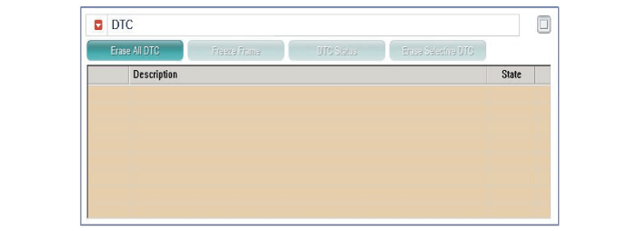
- Connect the GDS cable to the data link connector (DLC) on the lower panel of the driver's side crash pad.
- After turning the ignition switch ON, select "Active Test".
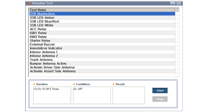
- Place the smart key near the corresponding antenna and operate it using the GDS.
- If the smart key LED blinks, the smart key is normal.
- If the smart key LED does not blink, check the smart key battery voltage.
- Antenna Activation
A. INTERIOR Antenna 1 B. INTERIOR Antenna 2 C. Trunk Antenna D. BUMPER / Trunk Antenna E. DRV_DR Antenna F. AST_DR Antenna - Connect the GDS cable to the data link connector (DLC) on the lower panel of the driver's side crash pad.
- Select "Antenna Status Check".
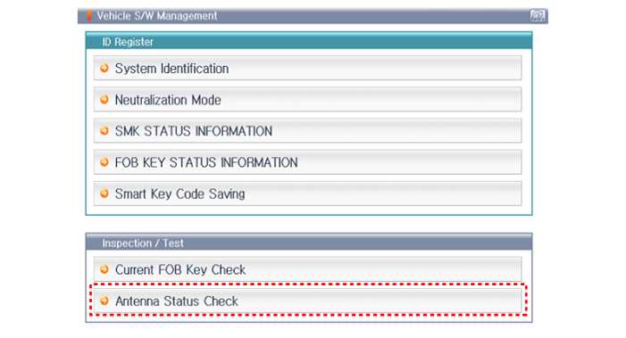
- After turning the IG switch ON, select "Antenna Status Check".

- Place the smart key near the corresponding antenna and operate it using the GDS.
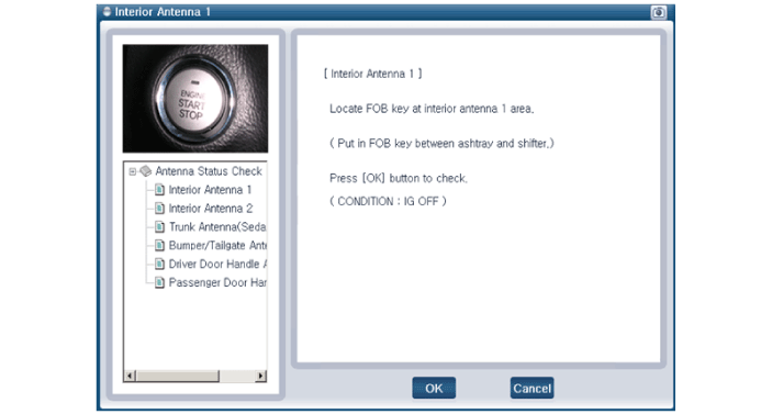
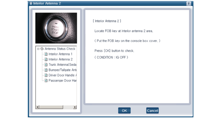
- If the smart key operates normally, the corresponding antenna, the smart key (transmission and reception) and the external receiver are normal.
- Antenna Status
A. INTERIOR Antenna 1 B. INTERIOR Antenna 2 C. INTERIOR Antenna 3 D. BUMPER / Trunk Antenna E. DRV_DR Antenna F. AST_DR Antenna - Connect the GDS cable to the data link connector (DLC) on the lower panel of the driver's side crash pad.
- After turning the ignition on, select "FOB Key Status INFO".
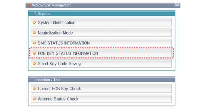
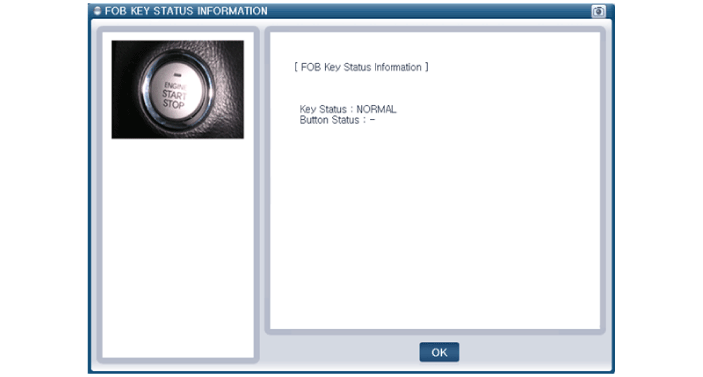
- Connect the GDS cable to the data link connector (DLC) on the lower panel of the driver's side crash pad.
- After turning IG on, select "SMK Status INFO".
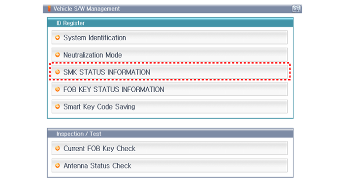
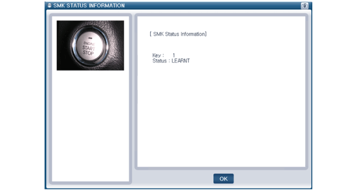
- Connect the GDS cable to the data link connector (DLC) on the lower panel of the driver's side crash pad.
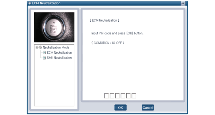
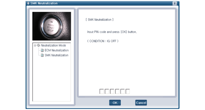
- After turning the ignition switch ON, select "Neutralization Mode".
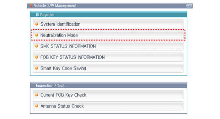
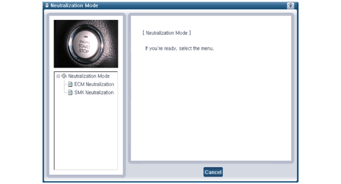
Test yourself
A quick Hyundai Sonata LF quiz: every answer comes with an explanation and a link to the manual page.
Was this page helpful?