Phone and GPS Antenna (Front Side)
Components
COMPONENTS
ILLUSTRATION
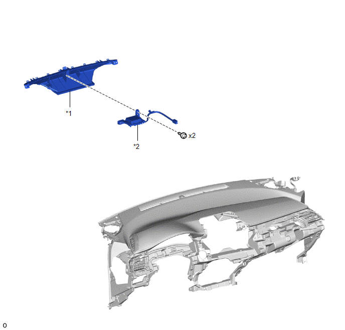
*1 |
DEFROSTER NOZZLE ASSEMBLY |
*2 |
PHONE AND GPS ANTENNA ASSEMBLY |
Removal
REMOVAL
PRECAUTION / NOTICE / HINT
The procedures required (adjustment, calibration, initialization or registration) that must be performed after parts are removed and installed or replaced during removal/installation of the GPS and phone antenna assembly are shown below.
Procedures Required After Replacement / Removal / Installation of PartsReplaced Part or Performed Procedure | Required Procedure | Effect/Inoperative Function When Required Procedure Is Not Performed | Link |
|---|---|---|---|
Disconnect the cable from the negative (-) battery terminal. |
Initialize Back Door Lock |
Door Lock Control System |
 |
Memorize Steering Angle Neutral Point |
Lane Departure Alert System (with Steering Control) |
|
|
Pre-Collision System |
CAUTION:
Some service operations affect the SRS airbag system. Before starting any service operation, carefully read the precautions for the SRS airbag system.
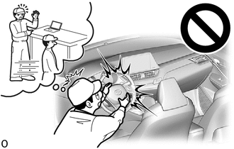
Click here
PROCEDURE
1. REMOVE INSTRUMENT PANEL SAFETY PAD SUB-ASSEMBLY
Click here
2. REMOVE DEFROSTER NOZZLE ASSEMBLY
Click here
3. REMOVE PHONE AND GPS ANTENNA ASSEMBLY
(a) Remove the 2 screws. |
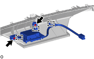 |
(b) Release the guides to remove the phone and GPS antenna assembly.
Installation
INSTALLATION
PROCEDURE
1. INSTALL PHONE AND GPS ANTENNA ASSEMBLY
(a) Engage the guide to install the phone and GPS antenna assembly. |
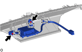 |
(b) Reinstall the 2 screws.
2. REINSTALL DEFROSTER NOZZLE ASSEMBLY
Click here
3. REINSTALL INSTRUMENT PANEL SAFETY PAD SUB-ASSEMBLY
Click here