Manual SOS Switch
Components
COMPONENTS
ILLUSTRATION
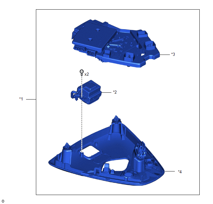
*1 |
READING LIGHT ASSEMBLY |
*2 |
MANUAL SOS SWITCH (EMERGENCY SWITCH ASSEMBLY) |
*3 |
COVER |
*4 |
GARNISH |
Removal
REMOVAL
PROCEDURE
1. REMOVE READING LIGHT ASSEMBLY
Click here
2. REMOVE MANUAL SOS SWITCH (EMERGENCY SWITCH ASSEMBLY)
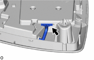
(a) Disconnect the connector. |
 |
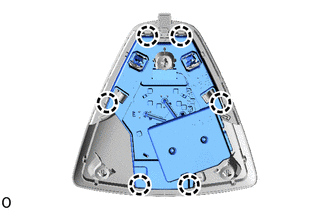
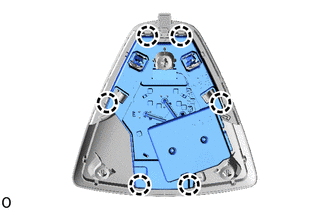
(b) Release the claws to remove the cover. |
 |
(c) Using a "TORX" T10 screwdriver, remove the 2 screws. |
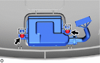 |
(d) Release the guides to remove the manual SOS switch (emergency switch assembly) from the garnish.
Inspection
INSPECTION
PROCEDURE
1. INSPECT MANUAL SOS SWITCH (EMERGENCY SWITCH ASSEMBLY)
(a) Check the resistance. (1) Measure the resistance according to the value(s) shown in the table below. Standard resistance:
If the resistance is not as specified, replace the manual SOS switch (emergency switch assembly). |
|
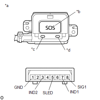
(b) Inspect the switch illumination.
(1) Apply battery voltage to the manual SOS switch (emergency switch assembly) and check that the illumination turns on.
OK:
Battery connection | Specified Condition |
|---|---|
Battery positive (+) → 5 (SLED) Battery negative (-) → 1 (GND) |
SOS switch illuminates |
If the resistance is not as specified, replace the manual SOS switch (emergency switch assembly).
(c) Inspect the indicator illumination.
(1) Apply battery voltage to the manual SOS switch (emergency switch assembly) and check that the illumination turns on.
OK:
Battery connection | Specified Condition |
|---|---|
Battery positive (+) → 7 (IND1) Battery negative (-) → 1 (GND) |
Red indicator illuminates |
Battery positive (+) → 3 (IND2) Battery negative (-) → 1 (GND) |
Green indicator illuminates |
If the resistance is not as specified, replace the manual SOS switch (emergency switch assembly).
Installation
INSTALLATION
PROCEDURE
1. REINSTALL MANUAL SOS SWITCH (EMERGENCY SWITCH ASSEMBLY)
(a) Engage the guides to reinstall the manual SOS switch (emergency switch assembly) on the garnish. |
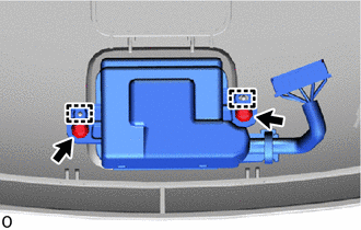 |
(b) Using a Torx T10 screwdriver, install the 2 screws.
(c) Engage the claws to reinstall the cover. |
 |
(d) Connect the connector.
2. REINSTALL READING LIGHT ASSEMBLY
Click here