Removal
REMOVAL
PRECAUTION / NOTICE / HINT
The procedures required (adjustment, calibration, initialization or registration) that must be performed after the parts have been removed, installed or replaced during removal/installation of the brake booster assembly are shown below.
Procedure Required After Replacing / Removing / Installing PartsReplacement part or procedure | Necessary Procedures | Effects / Inoperative Function When Necessary Procedure Not Performed | Link |
|---|---|---|---|
Disconnect the cable from the negative (-) battery terminal. |
Memorize Steering Angle Neutral Point |
Lane Departure Alert System (with Steering Control) |
 |
Pre-Collision System |
|||
Initialize Back Door Lock |
Door Lock Control System |
|
NOTICE:
Be sure to release the vacuum from the brake booster assembly before removing the master cylinder sub-assembly from the brake booster assembly.
PROCEDURE
1. REMOVE AIR HOSE NO. 1
Click here
2. REMOVE BRAKE MASTER CYLINDER SUB-ASSEMBLY
Click here
3. REMOVE BRAKE PEDAL RETURN SPRING
Click here
4. LOOSEN CLEVIS LOCK NUT
(a) Loosen the clevis lock nut of the master cylinder brake push rod clevis. |
|
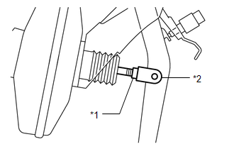
5. REMOVE PUSH ROD PIN
Click here
6. REMOVE ENGINE UNDER COVER NO. 1
Click here
7. REMOVE INSTRUMENT PANEL INSULATOR
(a) Remove the nut. |
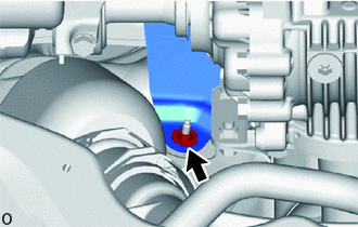 |
(b) Remove the 2 nuts and the instrument panel insulator. |
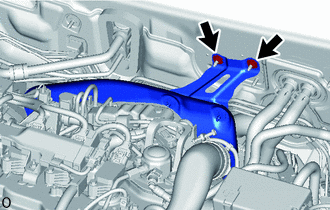 |
8. DISCONNECT HOSE CONNECTING CHECK VALVE TO CONNECTOR PIPE
(a) Slide the clip and disconnect the hose connecting the check valve to the connector pipe on the brake booster assembly. |
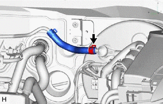 |
9. REMOVE BRAKE BOOSTER ASSEMBLY
(a) Disconnect the vacuum switch assembly connector. |
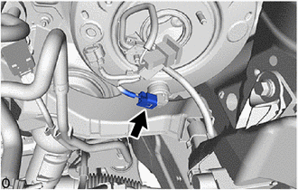 |
(b) Release the 5 clips to remove the brake tube clamp No. 1 from the brake tubes. |
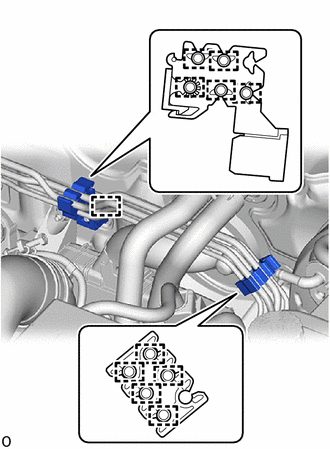 |
(c) Release the 5 clips to separate the brake tube clamps No. 2 from the brake tubes.
(d) Release the clip to remove the brake tube clamp No. 2 from the vehicle body.
(e) Release the 2 clips to separate the fuel tube from the fuel tube clamp. |
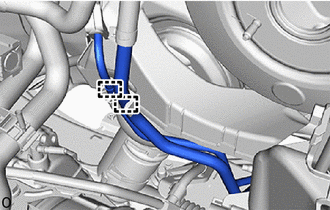 |
(f) Wrap protective tape around the vehicle body.
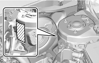
 |
Protective tape |
(g) Remove the 4 nuts and push the brake booster assembly toward the engine compartment. NOTICE: Be careful not to damage the brake lines. |
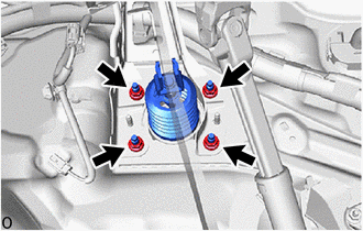 |
(h) Remove the master cylinder brake push rod clevis and the lock nut from the brake booster assembly.
(i) Remove the brake booster assembly from the vehicle body.
NOTICE:
Be careful not to damage the brake lines or the refrigerant lines.
10. REMOVE BRAKE BOOSTER GASKET
(a) Remove the brake booster gasket from the brake booster assembly.