Removal
REMOVAL
PRECAUTION / NOTICE / HINT
The procedures required (adjustment, calibration, initialization or registration) that must be performed after parts have been removed and installed or replaced, during removal/installation of the front axle shaft assembly, are indicated below.
Procedures Required After Replacement / Removal / Installation of PartsReplaced Part or Performed Procedure | Required Procedure | Effect/Inoperative Function When Required Procedure Is Not Performed | Link |
|---|---|---|---|
Front wheel alignment adjustment |
|
|
 |
HINT:
- Repeat the same procedure for the right side and the left side.
- The following procedure applies to the left side.
PROCEDURE
1. REMOVE FRONT WHEELS
Click here
2. REMOVE ENGINE UNDER COVER NO. 1
Click here
3. REMOVE ENGINE UNDER COVER REAR LH
Click here
4. REMOVE RH REAR ENGINE UNDER COVER
Click here
5. DRAIN CONTINUOUSLY VARIABLE TRANSAXLE FLUID
Click here
6. REMOVE FRONT AXLE SHAFT NUT
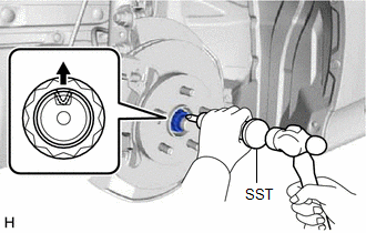
(a) Using the SST and a hammer, unstake the staked portion of the front axle shaft nut. SST: 09930-00010 NOTICE: Loosen the staked portion of the front axle shaft nut, otherwise the threads of the drive shaft may be damaged. |
 |
(b) While applying the brakes, remove the front axle shaft nut.
7. DISCONNECT FRONT SPEED SENSOR
Click here
8. DISCONNECT TIE ROD END SUB-ASSEMBLY
Click here
9. DISCONNECT FRONT STABILIZER LINK ASSEMBLY
Click here
10. DISCONNECT NO. 1 FRONT LOWER SUSPENSION ARM SUB-ASSEMBLY
Click here
11. DISCONNECT FRONT AXLE SHAFT ASSEMBLY
Click here
12. REMOVE FRONT AXLE SHAFT ASSEMBLY LH
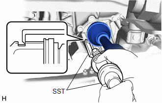
(a) Using the SST, remove the LH front axle shaft assembly. SST: 09520-01010 SST: 09520-24010 09520-32040 NOTICE:
|
 |
13. REMOVE FRONT AXLE SHAFT ASSEMBLY RH
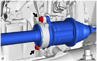
(a) Remove the 2 bolts from the RH front axle shaft assembly. |
 |
(b) Remove the RH front axle shaft assembly from the axle shaft bearing bracket.
NOTICE:
- Be careful not to damage the transaxle oil seal, inboard joint boot and axle shaft dust cover.
- Be careful not to drop the RH front axle shaft assembly.
HINT:
If the splines are difficult to engage, use a brass bar and a hammer to lightly tap the inboard joint assembly and remove it.
14. REMOVE FRONT AXLE SHAFT LH INBOARD JOINT BORE SNAP RING (for LH side)
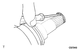
(a) Using a screwdriver, remove the LH axle shaft inboard joint bore snap ring. |
 |