Installation
INSTALLATION
PRECAUTION / NOTICE / HINT
HINT:
- Repeat the same procedure for the right side and the left side.
- The following procedure applies to the left side.
PROCEDURE
1. INSTALL LH FRONT AXLE SHAFT INNER JOINT SNAP RING (for LH side)
(a) Before installing a new LH axle shaft inner joint snap ring.
2. INSTALL LH FRONT AXLE SHAFT ASSEMBLY
(a) Apply genuine Toyota CVT FE fluid to the splines of the front drive shaft inner joint assembly.
(b) Apply MP grease to the lip of the LH front axle shaft oil seal.
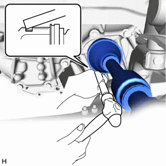
(c) Align the inner joint splines and, using a brass bar and a hammer, install the LH front axle shaft assembly. NOTICE:
HINT: Confirm that the axle shaft is fully seated by checking the reaction force and sound. |
 |
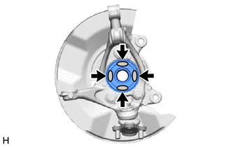
(d) Apply 0.1 to 0.3 g (0.00353 to 0.0105 oz.) of Toyota W body grease to each of the 4 areas shown in the illustration.
 |
Toyota Body Grease W |
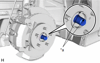
(e) Align the alignment marks and install the LH front axle shaft assembly onto the front axle hub sub-assembly. NOTICE:
|
|
3. INSTALL RH FRONT AXLE SHAFT ASSEMBLY
(a) Apply genuine Toyota CVT FE fluid to the splines of the front drive shaft inner joint assembly.
(b) Apply MP grease to the lip of the RH front axle shaft oil seal.
(c) Align the axle shaft splines and correctly install the RH front axle shaft assembly.
NOTICE:
- Take care not to damage the RH front axle shaft oil seal, the inner joint boot and the axle shaft dust cover.
- Insert the RH front axle shaft assembly while keeping it in a horizontal position.
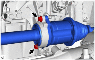
(d) Install the RH front axle shaft assembly with the 2 bolts. Torque: 64 N·m {650 kgf·cm, 47 ft·lbf} |
 |
(e) Proceed in the same way as for the LH side.
4. CONNECT FRONT SUSPENSION LOWER ARM SUB-ASSEMBLY NO. 1
Click here
5. INSTALL FRONT STABILIZER BAR LINK ASSEMBLY
Click here
6. CONNECT TIE ROD END SUB-ASSEMBLY
Click here
7. INSTALL FRONT SPEED SENSOR
Click here
8. INSTALL FRONT AXLE SHAFT NUT
(a) Clean the threaded portions of the front axle shaft assembly and a new front axle shaft nut using a residue-free solvent.
NOTICE:
- Make sure to perform this work even when using a new front axle shaft assembly.
- Keep the threaded portions free from oil or foreign objects.
(b) Using a 30 mm long socket wrench, install the front axle shaft nut. Torque: 216 N·m {2 203 kgf·cm, 159 ft·lbf} HINT: Keep the brake pedal depressed to prevent the axle shaft from rotating. |
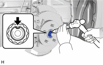 |
(c) Using a chisel and a hammer, stake the front axle shaft nut.
9. ADD CVT FLUID
Click here
10. CHECK FOR CVT FLUID LEAKAGE
11. INSTALL FRONT WHEELS
Click here
12. ADJUST FRONT WHEEL ALIGNMENT
Click here
13. INSTALL REAR LH ENGINE UNDER COVER
Click here
14. INSTALL REAR RH ENGINE UNDER COVER
Click here
15. INSTALL ENGINE UNDER COVER NO. 1
Click here
16. INSPECT SPEED SENSOR SIGNAL
Click here