Removal
REMOVAL
PRECAUTION / NOTICE / HINT
The procedures necessary (adjustment, calibration, initialization or registration) that must be performed after parts have been removed and installed or replaced during front axle hub subassembly removal/installation are shown below.
Procedures Required After Replacement / Removal / Installation of PartsReplaced Part or Performed Procedure | Required Procedure | Effect/Inoperative Function When Required Procedure Is Not Performed | Link |
|---|---|---|---|
Front wheel alignment adjustment |
|
|
 |
HINT:
- Repeat the same procedure for the right side and the left side.
- The following procedure applies to the left side.
PROCEDURE
1. REMOVE FRONT WHEEL
Click here
2. REMOVE FRONT AXLE SHAFT NUT
Click here
3. DISCONNECT FRONT SPEED SENSOR
(a) Remove the bolt and disconnect the front speed sensor and front hose from the front shock absorber assembly. NOTICE: Make sure to fully detach the front speed sensor and front hose from the front shock absorber assembly. |
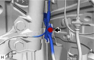 |
(b) Remove the bolt, release the clamp and disconnect the front speed sensor from the front shock absorber assembly and steering knuckle. NOTICE:
|
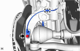 |
4. DISCONNECT TIE ROD END SUBASSEMBLY
Click here
5. DISCONNECT FRONT DISC BRAKE CALIPER ASSEMBLY
Click here
6. REMOVE FRONT DISC
Click here
7. DISCONNECT FRONT SUSPENSION LOWER ARM SUBASSEMBLY NO. 1
(a) Remove the bolt and 2 nuts, then disconnect the front suspension lower arm sub-assembly No. 1 from the front lower ball joint assembly. |
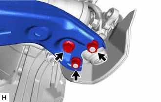 |
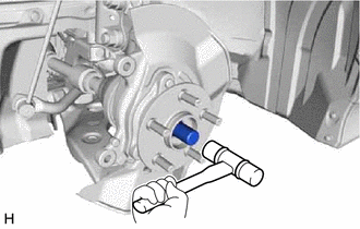
8. DISCONNECT FRONT AXLE SHAFT ASSEMBLY
(a) Make alignment marks on the front axle shaft assembly and the front axle hub subassembly. |
|
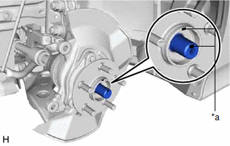
(b) Using a plastic hammer, disconnect the front axle shaft assembly from the front axle assembly. NOTICE:
HINT: If it is difficult to disconnect the front axle shaft assembly from the front axle assembly, tap the end of the front axle shaft assembly with a brass bar and hammer. |
 |
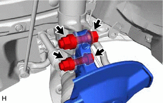
9. REMOVE FRONT AXLE ASSEMBLY
(a) Remove the 2 bolts, 2 nuts and front axle assembly from the front shock absorber assembly. NOTICE: When removing the nuts, prevent the bolts from turning. |
 |
10. REMOVE FRONT AXLE HUB SUBASSEMBLY
(a) Clamp the front axle assembly in a vise between aluminum plates. NOTICE: Do not overtighten the vise. |
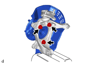 |
(b) Remove the 3 bolts, front axle hub subassembly and front disc brake dust cover from the steering knuckle.
NOTICE:
- Do not drop the front axle hub subassembly.
- Be careful not to damage the speed sensor rotor or contact surfaces.
- Do not allow foreign matter to contact the speed sensor rotor or contact surfaces.