Installation
INSTALLATION
PRECAUTION / NOTICE / HINT
PROCEDURE
1. INSTALL BRAKE ACTUATOR BRACKET BOLT BUSHING
(a) Install the brake actuator bolt bushing onto the brake actuator bracket assembly.
2. INSTALL NO. 1 BRAKE ACTUATOR HOUSING CLAMP
(a) Install the No. 1 brake actuator housing clamp onto the brake actuator bracket bushing.
3. INSTALL BRAKE ACTUATOR ASSEMBLY
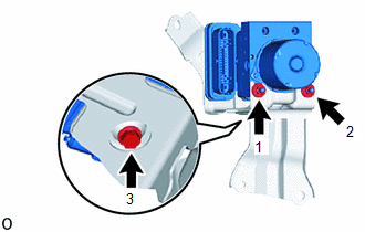
(a) Temporarily install the brake actuator assembly using the 2 nuts and the bolt.
(b) Fully tighten the 2 nuts and the bolt in the order shown in the illustration. Torque: 6.5 N·m {66 kgf·cm, 58 in·lbf} NOTICE:
|
 |
4. INSTALL BRAKE ACTUATOR WITH BRACKET
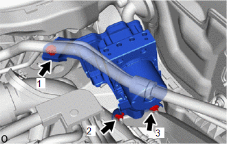
(a) Temporarily install the brake actuator with bracket to the vehicle body using the bolt and 2 nuts.
(b) Fully tighten the bolt and 2 nuts in the order shown in the illustration. Torque: 19 N·m {194 kgf·cm, 14 ft·lbf} NOTICE: Do not damage the brake lines. |
 |
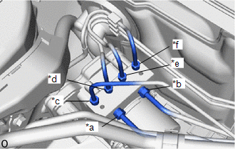
(c) Temporarily connect each brake line to its correct position on the brake actuator assembly with bracket as shown in the illustration. |
|
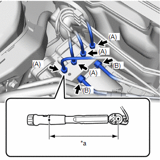
(d) Using a 10 mm and 12 mm flare nut wrench, connect the 6 brake lines to the brake actuator assembly. Torque: Specified torque (A): 15.2 N·m {155 kgf·cm, 11 ft·lbf} Specified torque (B): 19.5 N·m {199 kgf·cm, 14 ft·lbf} NOTICE:
HINT:
|
|
(e) Connect the connector to the brake actuator assembly and lock the lock lever.
NOTICE:
- Make sure the actuator connector can be connected smoothly. Prevent water, oil or dirt from entering the connector.
- Make sure the connector is securely locked.
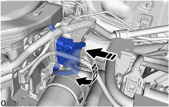
 |
Connect the connector |
 |
Lock the lock lever |
5. INSTALL FENDER APRON UPPER OUTER PANEL SUB-ASSEMBLY
Click here
6. INSTALL BATTERY
Click here
7. INSTALL RH FENDER APRON BODY BRACE
Click here
8. INSTALL LH FENDER APRON BODY BRACE
Click here
9. INSTALL LH WATERPROOF COVER PLATE
Click here
10. INSTALL NO. 1 HEATER AIR DUCT SPLASH SHIELD SEAL
Click here
11. INSTALL FRONT WIPER MOTOR AND LINK ASSEMBLY
Click here
12. CONNECT CABLE TO NEGATIVE BATTERY TERMINAL
Click here
NOTICE:
When the cable has been disconnected, some systems must be reset after the cable is reconnected.
Click here
13. BLEED BRAKE SYSTEM
Click here
14. CHECK BRAKE ACTUATOR USING TECHSTREAM
Click here
15. PERFORM SYSTEM VARIANT LEARNING
Click here
16. CHECK AND CLEAR DTCs
Click here