Installation
INSTALLATION
PROCEDURE
1. INSTALL BRAKE MASTER CYLINDER SUB-ASSEMBLY
NOTICE:
When installing a new brake master cylinder sub-assembly, remove the protective covers from the master cylinder piston and outlet ports.
(a) Install a new brake master cylinder O-ring to the brake master cylinder sub-assembly.
(b) Using a 13 mm long socket wrench, install the brake master cylinder sub-assembly to the brake booster assembly with a new nut.
Torque:
20 N·m {204 kgf·cm, 15 ft·lbf}
NOTICE:
- Handle the brake master cylinder sub-assembly with care. Do not drop it or subject it to impact. Do not reuse a brake master cylinder sub-assembly that has been dropped.
- Do not hold the brake master cylinder of the sub-assembly by the piston. Hold the brake master cylinder sub-assembly by its body or the brake master cylinder reservoir assembly when transporting it.
- Do not pull out the master cylinder piston.
- Do not hit or pinch the master cylinder piston, and do not allow it to be damaged in any way.
- When installing the brake master cylinder sub-assembly on the brake booster assembly, or when removing it from the brake booster assembly, keep the brake master cylinder sub-assembly horizontal or with its tip pointing down (master cylinder piston facing up) to prevent the master cylinder piston from falling out.
- Prevent foreign matter from entering the master cylinder piston. If any foreign matter reaches the master cylinder piston, remove it using a piece of cloth, then apply an even coat of lithium soap based glycol grease around the entire circumference (sliding part) of the master cylinder piston.
- Do not use any other type of grease or fluid.
- Be sure to release the vacuum from the brake booster assembly before removing the brake master cylinder sub-assembly from the brake booster assembly.
(c) Using a 13 mm long socket wrench, install the wire harness bracket to the brake master cylinder sub-assembly with the nut.
Torque:
20 N·m {204 kgf·cm, 15 ft·lbf}
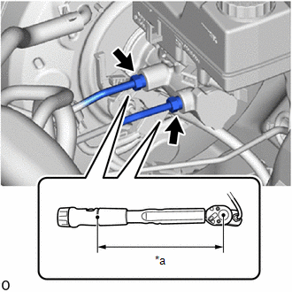
(d) Using a flare nut wrench, connect the 2 brake lines to the brake master cylinder sub-assembly. Torque: Specified torque: 19.5 N·m {199 kgf·cm, 14 ft·lbf} NOTICE:
HINT:
|
|
(e) Connect the reservoir level switch connector and engage the clamp.
2. INSTALL BATTERY
Click here
3. INSTALL COWL TOP OUTER PANEL SUB-ASSEMBLY
Click here
4. INSTALL RH COWL BODY MOUNTING REINFORCEMENT
Click here
5. INSTALL LH COWL BODY MOUNTING REINFORCEMENT
Click here
6. INSTALL LH WATER PROTECTION PLATE
Click here
7. INSTALL NO. 1 HEATER AIR DUCT SPLASH SHIELD SEAL
Click here
8. INSTALL FRONT WIPER MOTOR AND LINK ASSEMBLY
Click here
9. BLEED BRAKE SYSTEM
Click here