Fuel
Fuel injector assy (1MZ−FE/3MZ−FE)
In this manual: Fuel
71steps
~426min
4/5difficulty
Done 0 of 71
COMPONENTS
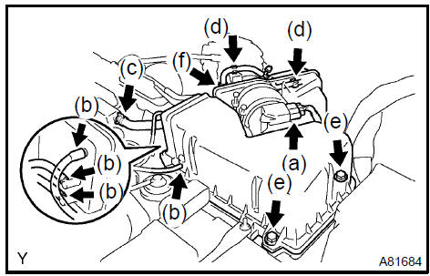 Remove air cleaner cap sub-assy 6. REMOVE EMISSION CONTROL VALVE SET (1MZ−FE ENGINE TYPE)
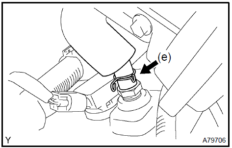
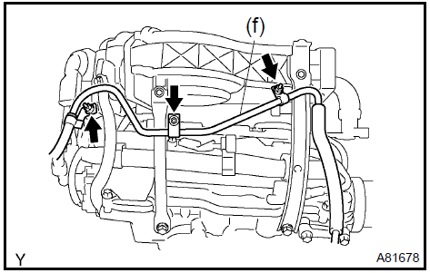
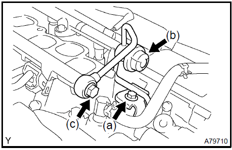 Separate fuel pipe sub-assy No.1 10. REMOVE FUEL INJECTOR ASSY

- DISCHARGE FUEL SYSTEM PRESSURE
- DRAIN ENGINE COOLANT
- REMOVE FRONT SUSPENSION UPPER BRACE CENTER
a. Remove the 2 nuts and upper brace.
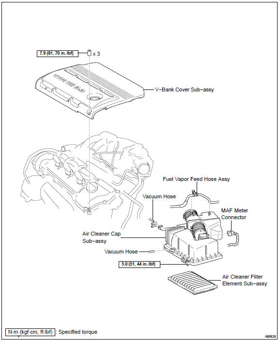
- REMOVE V−BANK COVER SUB−ASSY
- REMOVE AIR CLEANER CAP SUB−ASSY
- Disconnect the MAF meter connector.
- Disconnect the 4 vacuum hoses.
- Disconnect the ventilation hose No. 2.
- Remove the fuel vapor feed hose from the 2 hose clamps.
- Loosen the 2 air cleaner cap bolts.
- Loosen the air cleaner hose clamp bolt, and remove the air cleaner cap.
- Remove the air cleaner filter element.
Remove air cleaner cap sub-assy 6. REMOVE EMISSION CONTROL VALVE SET (1MZ−FE ENGINE TYPE)
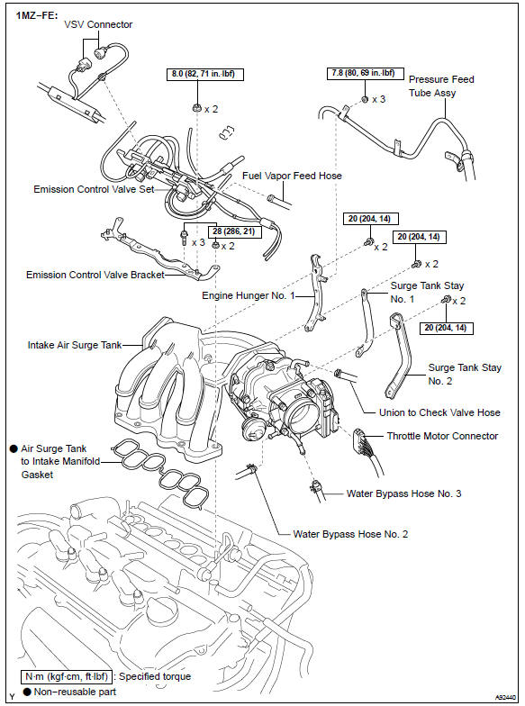
- Disconnect the 3 VSV connectors.
- Remove the wire harness clamp.

- Disconnect the fuel vapor feed hose No. 1.
- Disconnect the fuel vapor feed hose No. 2.
- Disconnect the 3 vacuum hoses.
- Remove the clamp.
- Remove the 2 nuts, and then remove the emission control valve set.
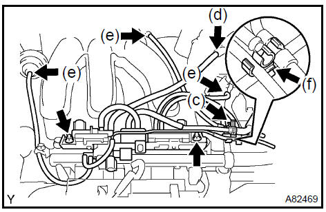
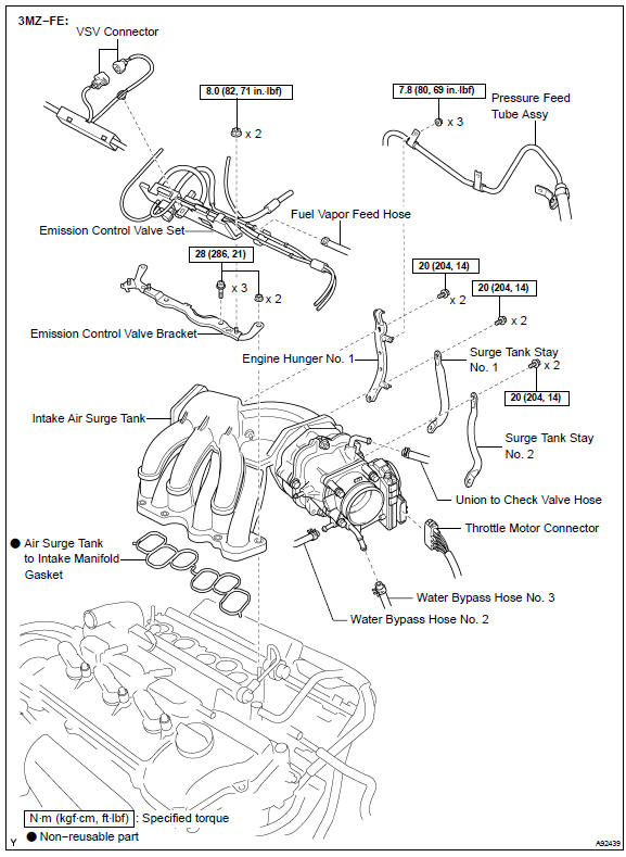
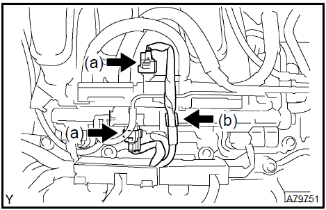
- Disconnect the 2 VSV connectors.
- Remove the wire harness clamp.
- Disconnect the fuel vapor feed hose No. 1.
- Disconnect the fuel vapor feed hose No. 2.
- Disconnect the 2 vacuum hoses.
- Remove the clamp.
- Remove the 2 nuts and the emission control valve set.

- Disconnect the throttle motor connector.
- Disconnect the water bypass hose No. 3.
- Disconnect the water bypass hose No. 2.
- Disconnect the union to check valve hose.
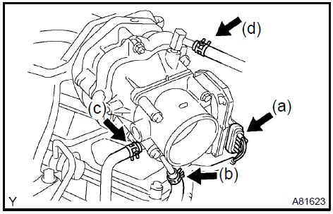
e. Disconnect the ventilation hose.
f. Remove the 3 nuts and separate the pressure feed tube.
- Remove the 2 bolts and engine hunger No. 1.
- Remove the 2 bolts and surge tank stay No. 1.
- Remove the 2 bolts and surge tank stay No. 2.
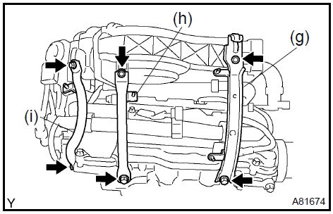
- Using a socket hexagon wrench 8, remove the 4 bolts.
- Remove the 2 nuts, emission control valve bracket and intake air surge tank.
- Remove the gasket from the intake air surge tank.
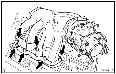
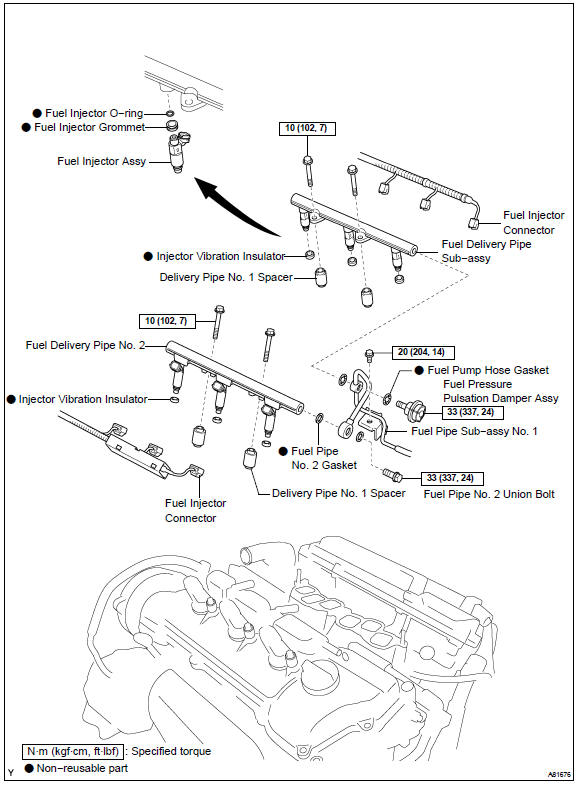
- Remove the bolt and disconnect the fuel pipe No. 1.
- Remove the fuel pressure pulsation damper and 2 gaskets.
- Remove the fuel pipe No. 2 union bolt and 2 gaskets.
Separate fuel pipe sub-assy No.1 10. REMOVE FUEL INJECTOR ASSY
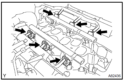
a. Disconnect the 6 fuel injector connectors.
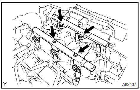
b. Remove the 4 bolts and 2 fuel delivery pipes together with the 6 fuel injectors.
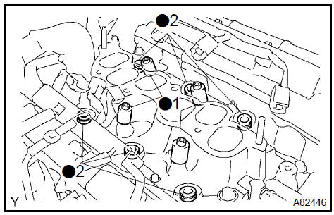
NOTICE: Be careful not to drop the fuel injectors when removing the fuel delivery pipe.c. Remove the 4 delivery pipe No. 1 spacers ( 1) and 6 insulators ( 2) from the intake manifold.
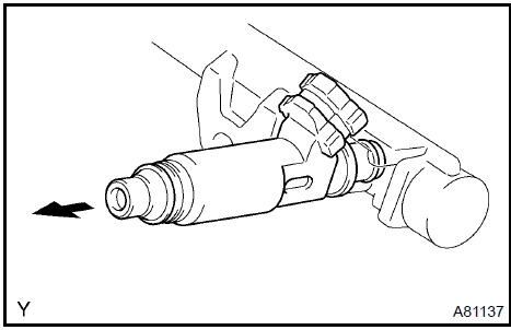
d. Pull out the fuel injector from the fuel delivery pipe.
- Install a new grommet to each injector.
- Apply a light coat of grease or gasoline to a new O−ring, and install it to each injector.
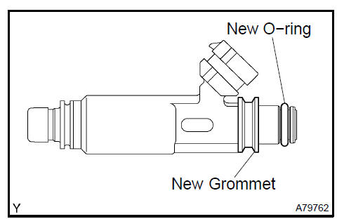
- Apply a light coat of grease or gasoline on the place where the fuel delivery pipe contacts the O−ring.
- Push the fuel injector while twisting it back and forth to install it in the fuel delivery pipe.
- Be careful not to twist the O−ring.
- After installing the fuel injector, check that it turns smoothly. If not, reinstall it with a new O−ring.
- Install 6 new insulators and the 4 delivery pipe No. 1 spacers to the intake manifold.
- Place the 2 fuel delivery pipes and the 6 fuel injectors together on the intake manifold.
g. Temporarily install the 4 bolts which are used to attach the fuel delivery pipe to the intake manifold.
NOTICE: After installing the fuel injector, check that it turns smoothly.If not, reinstall it with a new O−ring.
- Tighten the 4 bolts. Torque: 10 N·m
- Connect the 6 fuel injector connectors.

- Install 2 new gaskets and the fuel pipe No. 2 union bolt. Torque: 33 N·m
- Install 2 new gaskets and the fuel pressure pulsation damper. Torque: 33 N·m
- Install the fuel pipe No. 1 Ωith the bolt.
Torque: 20 N·m
- Install a new gasket to the intake air surge tank.
- Install the intake air surge tank and emission control valve bracket with the 2 nuts. Torque: 28 N·m
- Using a socket hexagon wrench 8, tighten the 4 bolts. Torque: 28 N·m
- Install the surge tank stay No. 2 Ωith the 2 bolts. Torque: 20 N·m
- Install the surge tank stay No. 1 Ωith the 2 bolts. Torque: 20 N·m
- Install the engine hunger No. 1 Ωith the 2 bolts. Torque: 20 N·m
- Install the pressure feed tube with the 3 nuts. Torque: 7,8 N·m
- Connect the ventilation hose.
- Connect the union to check valve hose.
- Connect the water bypass hose No. 2.
- Connect the water bypass hose No. 3.
- Connect the throttle motor connector.
- INSTALL EMISSION CONTROL VALVE SET (1MZ−FE ENGINE TYPE) Torque: 8 N·m
- INSTALL EMISSION CONTROL VALVE SET (3MZ−FE ENGINE TYPE) Torque: 8 N·m
- INSTALL AIR CLEANER CAP SUB−ASSY Torque: 5 N·m
- CHECK CONNECTION OF VACUUM HOSE
- ADD ENGINE COOLANT
- CHECK FOR ENGINE COOLANT LEAKS
- CHECK FOR FUEL LEAKS
- INSTALL V−BANK COVER SUB−ASSY
- INSTALL FRONT SUSPENSION UPPER BRACE CENTER
Test yourself
A quick Toyota Camry quiz: every answer comes with an explanation and a link to the manual page.
Was this page helpful?