Knock sensor
COMPONENTS
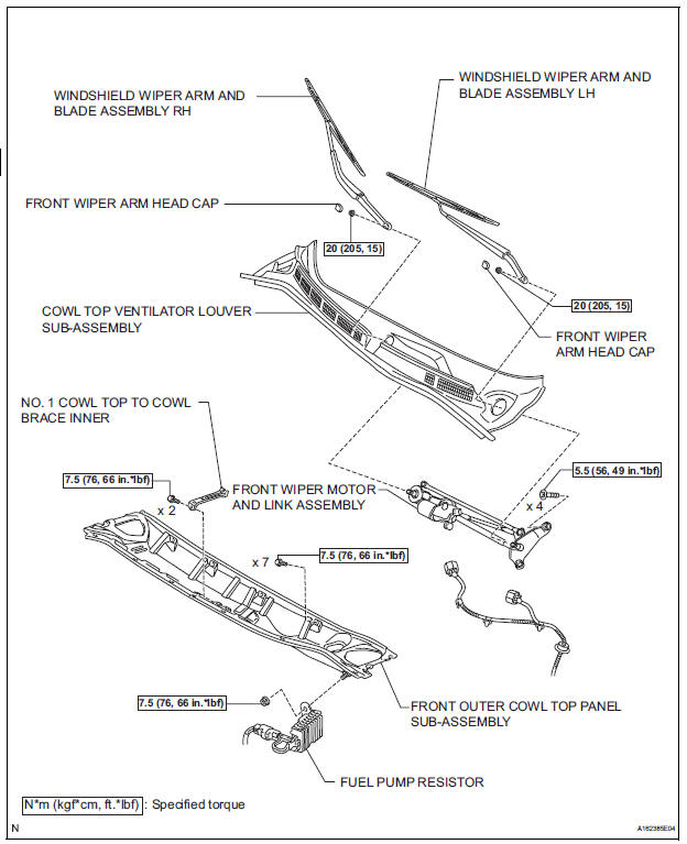
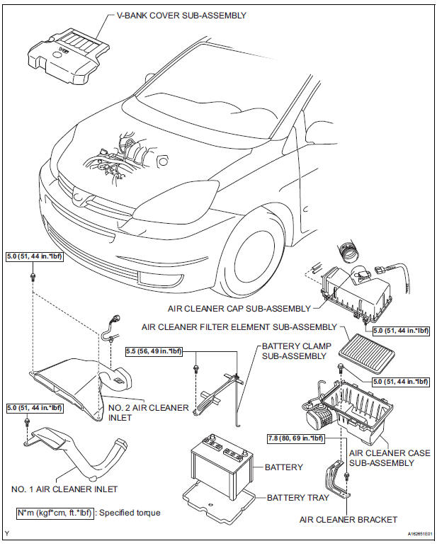
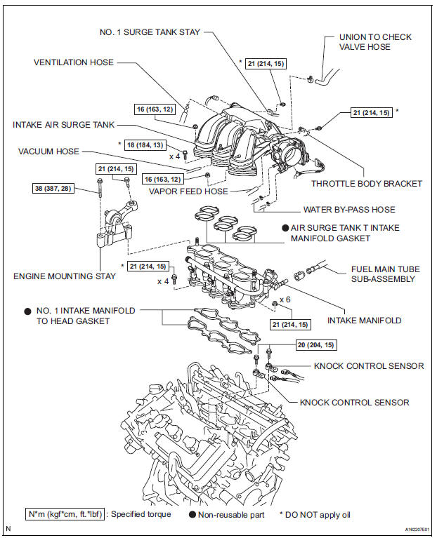
REMOVAL
1. DISCHARGE FUEL SYSTEM PRESSURE (See page FU-13) 2. REMOVE V-BANK COVER SUB-ASSEMBLY (See page EM-28) 3. DRAIN ENGINE COOLANT (See page CO-6) 4. REMOVE WINDSHIELD WIPER MOTOR ASSEMBLY HINT: (See page WW-4) 5. REMOVE FRONT OUTER COWL TOP PANEL SUBASSEMBLY (See page EM-27) 6. REMOVE AIR CLEANER CAP SUB-ASSEMBLY (See page ES-493) 7. REMOVE AIR CLEANER CASE SUB-ASSEMBLY (See page EM-28) 8. REMOVE INTAKE AIR SURGE TANK ASSEMBLY
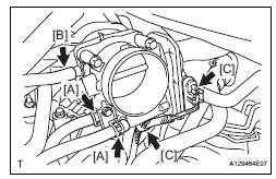
(a) Disconnect the 2 water by-pass hoses from the throttle body [A].
(b) Disconnect the vapor feed hose [B].
(c) Disconnect the throttle body connector and clamp [C].
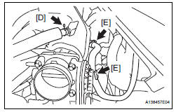
(d) Disconnect the ventilation hose [D].
(e) Disconnect the union to check valve hose [E].
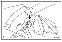
(f) Disconnect the connector [F].
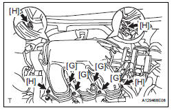
(g) Using a 5 mm socket hexagon wrench, remove the 4 bolts [G].
(h) Remove the 2 nuts, 2 bolts and intake air surge tank [H].
(i) Remove the gasket from the intake air surge tank [I].
9. REMOVE FUEL MAIN TUBE SUB-ASSEMBLY (See page EM-30) 10. REMOVE INTAKE MANIFOLD (See page EM-39)
11. REMOVE KNOCK CONTROL SENSOR
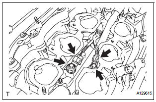
(a) Disconnect the 2 knock sensor connectors.
(b) Remove the 2 bolts and then remove the 2 knock control sensors.
INSPECTION
1. KNOCK CONTROL SENSOR
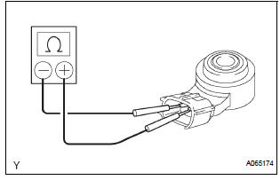
(a) Using an ohmmeter, measure the resistance between the terminals.
Resistance: 120 to 280 kΩ at 20 °C
If the resistance is not specified, replace the knock control sensor.
INSTALLATION
1. INSTALL KNOCK CONTROL SENSOR
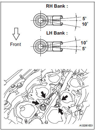
(a) Install the 2 knock control sensors with the 2 bolts as shown in the illustration.
Torque: 20 N*m (204 kgf*cm, 15 ft.*lbf) (b) Connect the 2 knock control sensor connectors.
2. INSTALL INTAKE MANIFOLD (See page EM-49) 3. INSTALL FUEL MAIN TUBE SUB-ASSEMBLY (See page EM-56) 4. INSTALL INTAKE AIR SURGE TANK
NOTICE: DO NOT apply oil to the bolts listed below.
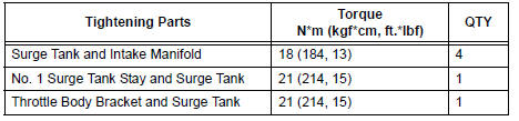
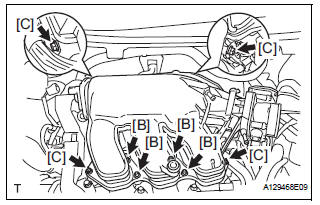
(a) Install a new gasket to the intake air surge tank [A].
(b) Using a 5 mm hexagon socket wrench, install the 4 bolts [B].
Torque: 18 N*m (184 kgf*cm, 13 ft.*lbf) (c) Install the intake air surge tank with the 2 nuts and 2 bolts [C].
Torque: Nut 16 N*m (163 kgf*cm, 12 ft.*lbf) Bolt 21 N*m (214 kgf*cm, 15 ft.*lbf)
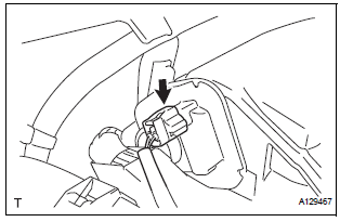
(d) Connect the connector [D].
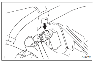
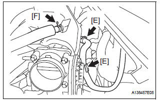
(e) Connect the union to check valve hose [E].
(f) Connect the ventilation hose No. 2 [F].
(g) Install the clamp and connect the throttle with motor body assembly connector [G].
(h) Connect the vapor feed hose [H].
(i) Connect the 2 water by-pass hoses to the throttle with motor body assembly [I].

5. INSTALL AIR CLEANER CASE SUB-ASSEMBLY (See page EM-59) 6. INSTALL AIR CLEANER CAP SUB-ASSEMBLY (See page ES-496) 7. ADD ENGINE COOLANT (See page CO-7) 8. INSPECT FOR ENGINE COOLANT LEAK (See page CO-1) 9. INSPECT FOR FUEL LEAK (See page FU-7) 10. INSTALL FRONT OUTER COWL TOP PANEL SUBASSEMBLY (See page EM-61) 11. INSTALL WINDSHIELD WIPER MOTOR ASSEMBLY
HINT: (See page WW-5)
12. INSTALL V-BANK COVER SUB-ASSEMBLY (See page EM-63)
Test yourself
A quick Toyota Sienna quiz: every answer comes with an explanation and a link to the manual page.