ComponentsCOMPONENTS
ILLUSTRATION 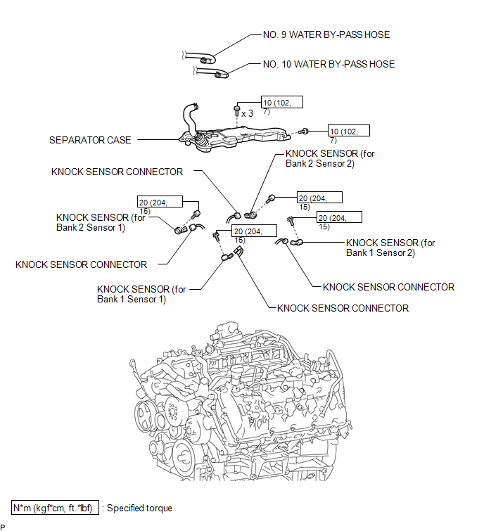
InspectionINSPECTION
PROCEDURE
1. INSPECT KNOCK SENSOR 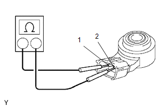
(a) Measure the resistance according to the value(s) in the table below.
Standard Resistance:
Tester Connection | Condition | Specified Condition |
1 - 2 |
20 °C |
120 k to 280 kΩ |
If the result is not as specified, replace the knock sensor.
InstallationINSTALLATION
HINT:
Perform "Inspection After Repairs" after replacing the knock sensor (See page  ).
PROCEDURE
1. INSTALL KNOCK SENSOR
HINT:
Perform "Inspection After Repairs" after replacing the knock sensor (See page ).
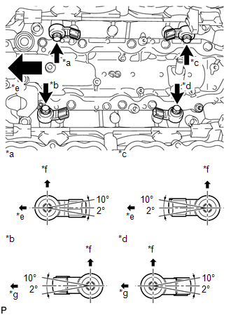
(a) Install the 4 knock sensors with the 4 bolts so that the sensors are angled as shown in the illustration.
Torque:
20 N·m {204 kgf·cm, 15 ft·lbf} Text in Illustration
*a |
Bank 2 Sensor 1 |
*b |
Bank 1 Sensor 1 |
*c |
Bank 2 Sensor 2 |
*d |
Bank 1 Sensor 2 |
*e |
Front |
*f |
Upper |
*g |
Rear |
NOTICE:
The acceptable installation angle of the knock sensor is between 10° upward and 2° downward from the horizontal position. |
 |
(b) Connect the 4 knock sensor connectors.
2. INSTALL SEPARATOR CASE
(a) Install the separator case with the 4 bolts.
Torque:
10 N·m {102 kgf·cm, 7 ft·lbf}
3. CONNECT NO. 9 WATER BY-PASS HOSE
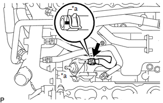
(a) Connect the No. 9 water by-pass hose to the separator case, and slide the clamp to secure the hose. Text in Illustration
HINT:
Make sure the hose color matches the connection area color. |
 |
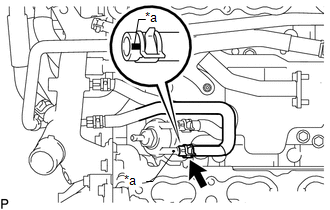
4. CONNECT NO. 10 WATER BY-PASS HOSE
(a) Connect the No. 10 water by-pass hose to the separator case, and slide the clamp to secure the hose. Text in Illustration
HINT:
Make sure the hose color matches the connection area color. |
 |
5. INSTALL INTAKE MANIFOLD
(See page )
RemovalREMOVAL
PROCEDURE
1. REMOVE INTAKE MANIFOLD
(See page  )
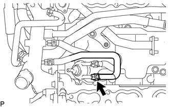
2. DISCONNECT NO. 10 WATER BY-PASS HOSE
(a) Slide the clamp and remove the No. 10 water by-pass hose from the separator case. |
 |
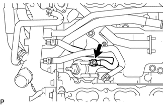
3. DISCONNECT NO. 9 WATER BY-PASS HOSE
(a) Slide the clamp and remove the No. 9 water by-pass hose from the separator case. |
 |
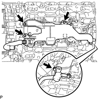
4. REMOVE SEPARATOR CASE
(a) Remove the 4 bolts and separator case. |
 |
5. REMOVE KNOCK SENSOR
(a) Disconnect the 4 knock sensor connectors. |
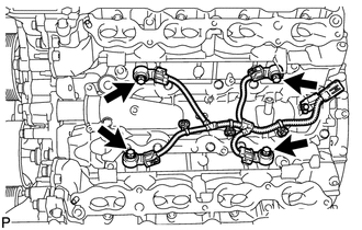 |
(b) Remove the 4 bolts and 4 knock sensors. |