Electrical system
Calibrating Blind Spot Monitor control unit -J1086-/-J1087-
In this manual: Electrical system
~2min read
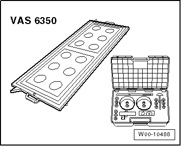
 Note Before the actual calibration process of the control units, the calibration unit -VAS 6350- needs to be set up as described in the following chapter. Special tools and workshop equipment required |
Calibration unit -VAS 6350-Vehicle diagnostic testerDuring the calibration process the following should not occur:Vehicle doors should not be opened or closed.There should be no-one in the vehicle.No-one should pass through the space between the vehicle and the calibration unit for lane change assist -VAS 6350/4-.Procedure: |
 |
The green LED -1- must light up. Note If the red LED -2- lights up: Check the calibration unit for lane change assist -VAS 6350/4-.
Note
The vehicle shown in the illustration may differ from the actual vehicle. |
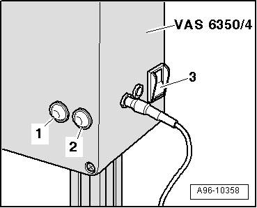 |
During the program sequence you will be requested to change the calibration unit for lane change assist -VAS 6350/4- from the left to the right-hand side of the calibration unit -VAS 6350-.
Dimension -a- = 606 mm (measured from upper edge of calibration unit to floor).Setting dimension right = 621 mm (read off from measuring scale -1-). |
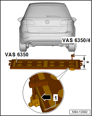 |
The green LED -1- must light up.
|
|
Test yourself
A quick Volkswagen Golf quiz: every answer comes with an explanation and a link to the manual page.
Was this page helpful?