Running gear, axles, steering
Removing and installing swivel joint
In this manual: Running gear, axles, steering
~3min read
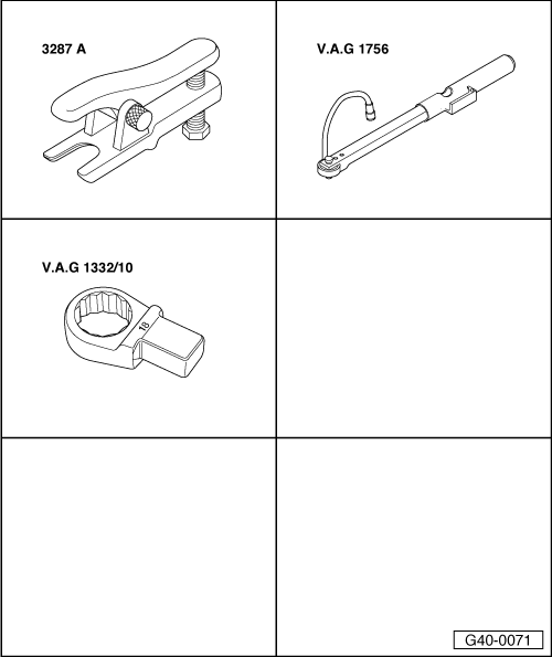
Special tools and workshop equipment required
Ball joint puller -3287 A-
Angle wrench -V.A.G 1756-
Ring spanner insert -V.A.G 1332/10-
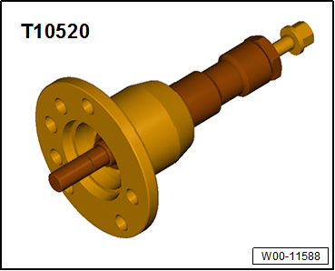
Press tool -T10520-Removing
|
 |
 Caution Wheel bearings must not be subjected to load after bolt securing drive shaft to wheel hub has been loosened. If wheel bearings are loaded with weight of vehicle, bearing will be damaged. This reduces the service life of the wheel bearing. It is not permissible to loosen drive shaft bolt more than 90° if vehicle is standing on its wheels. Do not attempt to move the vehicle without the drive shafts fitted as this would damage the wheel bearing. If a vehicle nevertheless has to be moved, comply with the following:
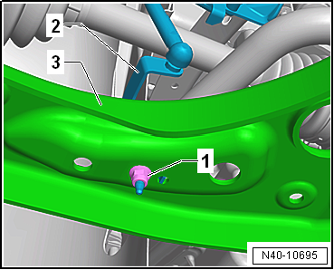
Vehicles with vehicle level sender
Continuation for all vehicles |
 |
|
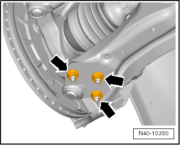 |
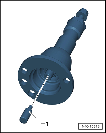
Before using press tool -T10520- ensure that thrust piece -1- is inserted.Using press tool -T10520-: |
 |
|
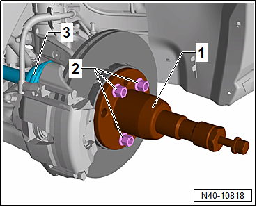 |
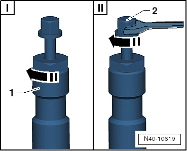
 Note At the end of the procedure or for pressing out drive shaft further the spindle must be moved to its original position in order to deploy the hydraulic force!
|
 |
InstallingInstall in reverse order of removal, observing the following:
|
 |
Note
Ensure that bellows are not damaged or twisted. Note
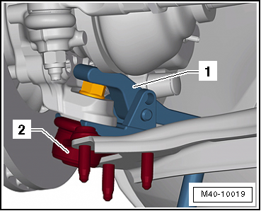
Lever on vehicle level sender must face towards outside of vehicle.Thread of vehicle level sender must be screwed into outer hole in suspension link. Retaining lug for vehicle level sender must engage in inner hole in order to guarantee correct installation position.
Note During this step, vehicle must not be standing on its wheels or wheel bearing will be damaged.
Specified torques→ Chapter „Assembly overview - lower suspension link, swivel joint“→ Chapter „Assembly overview - front vehicle level senders“→ Chapter „Assembly overview - drive shaft“→ Chapter „Torque settings for wheel bolts“ |
 |
Test yourself
A quick Volkswagen Golf quiz: every answer comes with an explanation and a link to the manual page.
Was this page helpful?