Strut
PROCEDURE
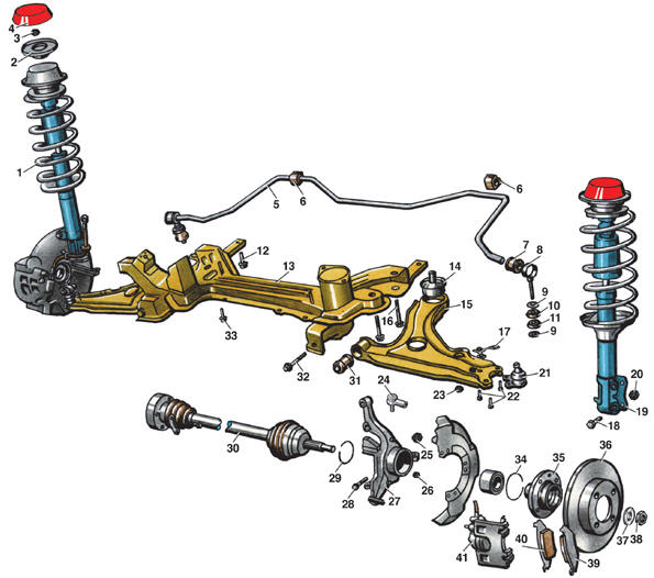
Front Suspension 1 – strut; 2 – limit washer; 3 – nut; 4 – protective cap; 5 – stabilizer bar; 6 – rubber bushing; 7 – bushing; 8 – strut; 9 – spring seat; 10, 11 – joints; 12 – bolt; 13 – beam; 14 – bushing; 15 – front suspension arm; 16 – bolt; 17 – plate with nuts; 18 – bolt; 19 – bracket; 20 – nut; 21 – ball joint; 22 – bolt; 23 – nut; 24 – tie rod end; 25 – nut; 26 – nut; 27 – steering knuckle; 28 – bolt; 29 – retaining ring; 30 – axle shaft; 31 – bushing; 32 – bolt; 33 – bolt; 34 – retaining ring; 35 – hub; 36 – brake disc; 37 – washer; 38 – nut; 39 – outer brake pad; 40 – inner brake pad; 41 – caliper

Strut 1 – bracket; 2 – shock absorber strut; 3 – lower spring seat; 4 – shock absorber strut rod; 5 – spring; 6 – nut; 7 – mount; 8 – upper spring seat; 9 – compression bumper; 10 – protective boot
Removal PROCEDURE 1. Apply the parking brake. 2. Loosen the wheel bolts. 3. Raise the front of the vehicle and set it on supports. 4. Remove the wheels. 5. Install an additional support under the axle shaft near the outer CV joint boot. 6. Remove upper protective cap 4 (see figure Front Suspension) from strut 1 in the engine compartment. 7. Unscrew nut 3 while holding the shock absorber strut rod with a hex key. 8. Remove limit washer 2. 9. Unscrew nut 23 of stabilizer bar 5 (only on Golf Carat, GTI, GTO models with sport chassis and Jetta models). 10. Press out the tie rod ball joint (see paragraphs 6–8 of subsection 8.2). 11. Remove brake caliper 41 and hang it on wire (see paragraphs 11–12 of subsection 10.7). 12. Trace the outline of strut mounting bracket 19 on steering knuckle 27 for accurate positioning during subsequent installation. 13. Unscrew nuts 20 with captive washers and remove two bolts 18 with captive washers. 14. Lower lower control arm 15, remove the upper end of strut 1 from the body apron opening, then remove strut 1 from steering knuckle 27. Disassembly PROCEDURE 1. Clamp the lower end of the strut in a vise.
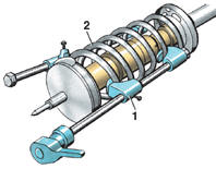
2. Install special tool 1 to compress spring 2. 3. Compress the spring until upper seat 8 (see fig. Front Suspension Strut) of spring 5 rotates freely. 4. Loosen nut 6 while holding piston rod 4 of the shock absorber strut with a hex key. 5. Remove strut mount 7. 6. Remove upper spring seat 8. 7. Mark upper end of spring for correct installation. 8. Remove spring together with special tool. 9. Remove compression bump stop 9. 10. Remove protective boot 10. Checking Condition of Shock Absorber Strut PROCEDURE 1. Check condition of shock absorber strut by moving piston over full stroke. If binding or lack of resistance is found along piston stroke, or if traces of shock absorber fluid leakage are visible, replace shock absorber struts. 2. Clean springs of dirt and carefully inspect them. If cracks or deformed coils are found, replace spring with a new one. It is recommended to replace both springs as a set.
Warning There are eight spring size groups. Always replace springs with new ones having the same designation and color code. Installation PROCEDURE 1. Install front suspension strut in reverse order of removal. 2. Spring 5 must be compressed with special tool during installation. 3. Tighten nut 6 to 40 N·m. Installation Warning Replace nuts 20 (see fig. Front Suspension) with captive washers with new ones. If nuts with flanges were previously installed, replace them with nuts with captive washers together with bolts 18. PROCEDURE 1. Install bracket 19 (see fig. Front Suspension) onto steering knuckle 27, insert upper end of strut 1 into body apron hole, install bolts 18 and start new nuts 20. 2. Install limiting washer 2. 3. Tighten new nut 3 to 60 N·m. 4. Install bracket 19 aligned with marks made earlier on steering knuckle 27 and tighten nuts 20 to 95 N·m (or to 80 N·m for nuts installed before February 1990). 5. Install brake caliper 41 (see item 9 of subsection 10.7). 6. Install ball joint (see item 7 of subsection 8.2). 7. Tighten nut 23 of stabilizer bar 5 (only on Golf Carat, GTI, GTO with sport chassis, and Jetta). 8. Install upper protective cap 4 on strut. 9. Install wheel and lower vehicle to ground. 10. Tighten wheel bolts to 110 N·m. 11. Check wheel alignment (see subsection 9.1.7).
Test yourself
A quick Volkswagen Golf quiz: every answer comes with an explanation and a link to the manual page.