General, Technical data
Safety Precautions
Safety Precautions during Road Test with Testing Equipment
If Testing Equipment Must Be Used during a Road Test, Note the Following:
WARNING
Risk of accident due to distractions and testing equipment that is not secured properly.The front passenger airbag could pose a risk if it deploys in a collision
- Operating testing equipment while driving is a distraction.
- Testing equipment that is not secured properly increases the risk of personal injury.
To Prevent Personal Injury and Damage to the Electrical/Electronic Components, Note the Following:
- Only connect and disconnect test equipment when the ignition is off.
Caution
Risk of destroying electronic components when disconnecting the battery.Follow the steps when disconnecting the battery.
- Disconnect the battery.
Safety Precautions when Working on Start/Stop System
WARNING
Risk of injury if the engine starts automatically in vehicles with the Start/Stop System.
- Deactivate the Start-Stop system when working on the vehicle. Turn off the ignition.
- Only switch the ignition on briefly when necessary.
Identification
Transmission Identification
- Chapter "Transmission Identification, Front Wheel Drive"
- Chapter "Transmission Identification, All Wheel Drive"
Technical Data
Transmission/Engine Allocation- Chapter "Transmission/Engine Allocation, Golf and Golf Wagon, Manual Transmission 02Q"
- Chapter "Transmission/Engine Allocation, Golf, Manual Transmission 02Q with Front Axle Differential Lock"
- Chapter "Transmission/Engine Allocation, CC, Passat, Golf, Manual Transmission 0FB"
- Chapter "Transmission/Engine Allocation, CC, Manual Transmission 02Q"
- Chapter "Transmission/Engine Allocation, Passat, Manual Transmission 02Q"
- Chapter "Transmission/Engine Allocation, Passat, Manual Transmission 0BB"
- Chapter "Transmission/Engine Allocation, Golf All Wheel Drive, Golf Wagon All Wheel Drive, Manual Transmission 02Q"
- Chapter "Transmission/Engine Allocation, CC All Wheel Drive, Manual Transmission 02Q"
- Chapter "Transmission/Engine Allocation, Passat All Wheel Drive, Manual Transmission 02Q"
- Chapter "Transmission/Engine Allocation, Tiguan All Wheel Drive, Manual Transmission 02Q"
Capacities
Manual Transmission Capacity
| Manual transmission capacity | Refer to → Fluid Capacity Tables; Rep. Gr.03 |
Bevel Box Capacity
| Bevel box capacity | Refer to → Fluid Capacity Tables; Rep. Gr.03 |
Gear Ratio Calculation
Example:
| 6th Gear | Final Drive | |
| Drive gear | ZG1 = 46 | ZA1 = 24 |
| Driven gear | ZG2 = 33 | ZA2 = 70 |
i = ZG2 : ZG1.
iG = gear ratio = ZG2 : ZG1 = 33 : 46 = 0.717iA= axle ratio= ZA2 : ZA1= 70 : 24= 2.917
itotal = total ratio= iG x iA = 0.717 x 2.917 = 2.0911) Z1 = Number of teeth on the drive gear, Z2 = Number of teeth on the driven gear
Overview - Transmission
Overview - Transmission, Front Wheel Drive
Name
The -arrows- point in the direction of travel.
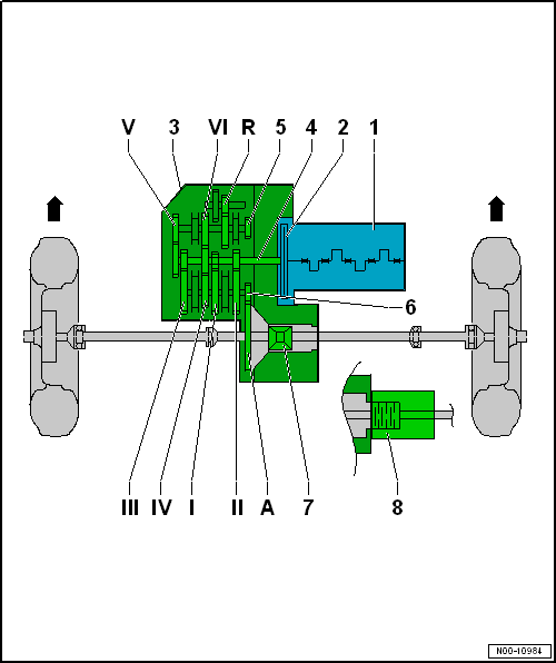
- Engine
- Clutch
- Manual Transmission
- Input Shaft
- 5th, 6th and Reverse Gear Output Shaft
- 1st through 4th Gear Output Shaft
- Differential
- Front Axle Differential Lock
- With Haldex clutch
- Installed in connection with gasoline engine depending on the vehicle equipment level.
Ratio
The -arrows- point in the direction of travel.
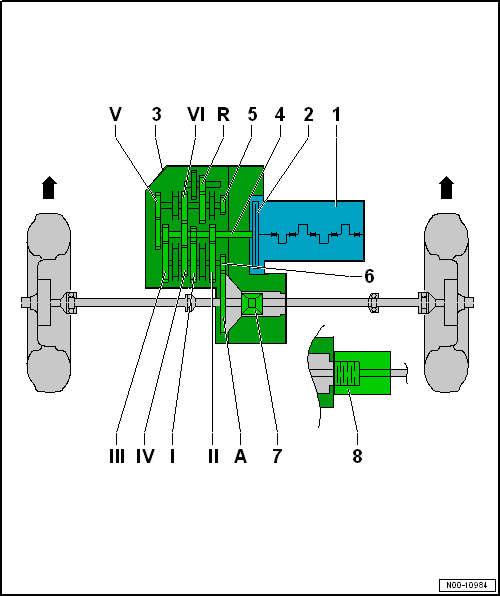
- 1st Gear
- 2nd Gear
- 3rd Gear
- 4th Gear
- 5th Gear
- 6th Gear
R - Reverse Gear
A - Final Drive
Electrical Components
Component Location Overview - Electrical Components
Component Location Overview - Electrical Components, Manual Transmission

- Transmission Neutral Position Sensor -G701-
- Installed location: in the area of the shift unit under the selector shaft bracket.
- Removing and installing.
- Back-Up Lamp Switch -F4-
- Installed location: in the area of the shift unit under the selector shaft bracket.
- Removing and installing.
Component Location Overview - Electrical Components, Clutch Mechanism
Clutch Position Sensor -G476--arrow-, Scirocco, CC, Golf Cabriolet, Passat, Tiguan
Component location: In the engine compartment under the hose -1- on the clutch master cylinder -2- behind the line -3-.
The connector -4- is on the Clutch Position Sensor -G476-.
Clutch Position Sensor -G476-, Removing and installing.

Clutch Position Sensor -G476--arrow-, Golf and Golf Wagon
Installed location: in the passenger compartment on the clutch master cylinder.
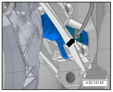
Clutch Position Sensor -G476-, Removing and installing.
Repair Information
General Repair Information
The highest level of care and cleanliness along with tools that function properly are required to ensure a proper and successful transmission repair. The usual basic safety precautions apply when making vehicle repairs.Some general repair information for individual repair procedures, that appear many times throughout the manual, is summarize here. They apply to this repair manual.
Special ToolsRefer to Workshop Equipment and Special Tools for a complete list of special tools used in the repair manual.
Transmission- Make sure that the alignment bushings between the engine and transmission are positioned correctly when installing the manual transmission.
- Clean the contact surfaces when installing brackets as well as parts that have been waxed. Contact surfaces must be free of wax and grease.
- Allocate the bolts and other components. Refer to the Parts Catalog.
- Fill the transmission fluid when repairing the manual transmission.
Seals and Gaskets
- After removing gaskets, examine the contact surface on housing/shaft for burrs resulting from removal or for other damage.
- Thoroughly clean the separating surfaces and apply Sealant.
- Allocation. Refer to the Parts Catalog.
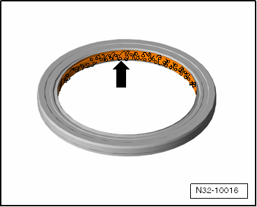
- Fill the space between the sealing lips halfway with Grease-arrow- before installing the radial shaft seal.
- Grease allocation. Refer to the Parts Catalog.
- The open side of the gaskets point toward the fluid to be sealed in.
- Lightly lubricate the O-rings before inserting to prevent the rings from being crushed during assembly.
Sealant
- Clean the housing separating surfaces thoroughly before applying the Sealant.
- Apply Sealant evenly and not too thick.
- Allocation. Refer to the Parts Catalog.
- Sealant must not go into the bleed holes.
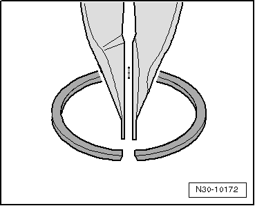
Retainers
- Replace the circlips.
- Do not stretch the circlips.
- The circlips must rest at the bottom of the groove.
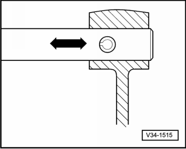
- Replace the adapter sleeves. Installed position: slot is lengthwise to line of force.
Bolts and Nuts
- Always loosen or tighten bolts and nuts on covers and housings diagonally.
- Especially delicate parts, such as clutch pressure plates, must not be distorted. Loosen and tighten bolts and nuts in stages in a diagonal sequence.
- The tightening specifications given apply to unoiled bolts and nuts.
- Replace self-locking bolts and nuts after removing them.
- Make sure the contact surfaces and visible surfaces on the nuts and bolts are waxed after assembling.
- Use a thread cutter to clean all threaded holes containing self-locking bolts to remove any locking compound residue. Otherwise the bolts could shear the next time they are removed.
- Please make sure that the thread pitch is correct so that the proper thread cutter is used during cleaning, and the thread does not get damaged.
Bearings
- Insert the bearings with transmission fluid.
- Install the new tapered roller bearings. It is not necessary to oil them.
- Install needle bearings with the lettered side (thicker metal) facing the fitting tool.
- Replace all the tapered roller bearings that are on the same shaft, and use tapered roller bearings from the same manufacturer.
- Do not interchange inner and outer bearing races with those from other bearings of the same size, bearings are paired.
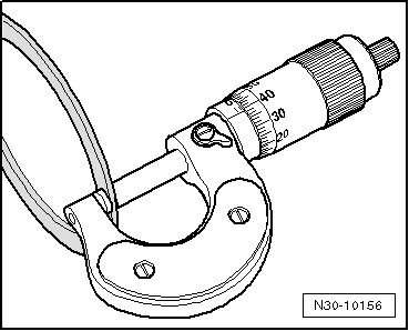
Shims
- Measure the shims at several locations with a micrometer caliper. It is possible to measure the necessary shim thickness by the different tolerances.
- Check for burrs or damage.
- Only install perfect shims.
Synchronizer Rings
- Do not interchange them. When reusing synchronizer rings, always install on the same gear wheel.
- Check for wear and replace if necessary.
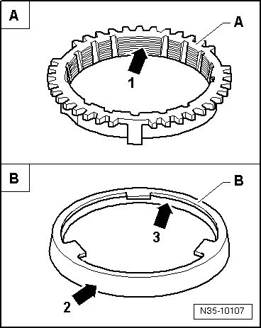
- Check the grooves -arrow 1- on the synchronizer ring -A- and the inner race for flat areas (grooves are worn).
- The coating on the synchronizer rings must not be damaged.
- If an intermediate ring -B- is installed, check this intermediate ring on the outer friction surface -arrow 2- and inner friction surface -arrow 3- for "grooves", "wear grooves" and "blue coloring (from overheating)".
- Check taper of drive gear for "grooves" and "scoring".
- Coat the synchronizing with transmission fluid and then install.
Toothed Gears, Synchronizer Hubs
- Clean before installing. Warm using the Inductive Heater -VAS6414- to a maximum 100 ºC (212 ºF).
- Pay attention to the installed location.
Selector Gears
- After assembling, check the selector gears for minimum axial clearance and ease of movement.
Clutch Mechanism
Disconnect the battery. Refer to → Electrical Equipment.
If the battery is to be reconnected: Refer to → Electrical Equipment.
Clutch
- Do not tilt the clutch pressure plate. Loosen and tighten it diagonally and in small steps.
- To reduce odor caused by a burnt clutch, thoroughly clean the clutch housing and the flywheel running surface with a clean cloth.
Test yourself
A quick Volkswagen Tiguan quiz: every answer comes with an explanation and a link to the manual page.