Tire Pressure Sensor
Overview - Tire Pressure Monitoring Sensor
Overview - Tire Pressure Monitoring Sensor with Valve
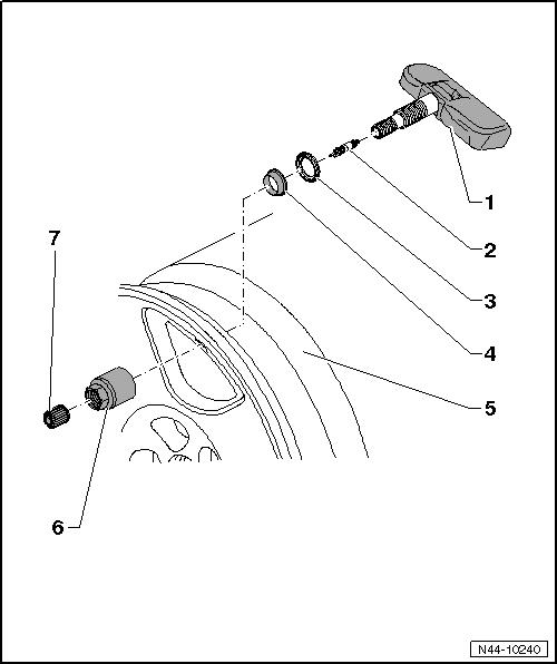
- Tire Pressure Monitoring Sensor
- Supplied complete as a service part
- Removing and Installing.
- When battery is discharge, the entire Tire Pressure Monitoring Sensor must be replaced
- After using a wheel repair kit, the bore for the valve and opening of the pressure sensor must be wiped clean.
- Valve Insert
- Allocation. Refer to the Parts Catalog.
- Replace at every tire change
Note
Use only original manufacturer valve insert, it has a special coating!
- Sealing Washer
- is slightly deformed when tightening the union nut -item 6-
- Seal
- Disc Wheel
- Mounting tires with emergency running characteristics.
- Mounting tires (wheels with tire pressure monitoring system).
- Union Nut
- 8 N·m
- Valve Cap
- Use only original valve caps from the repair set. Refer to the Parts Catalog.
- Do not use Comfort valve caps and metal caps
Overview - Tire Pressure Monitoring Sensor without Valve
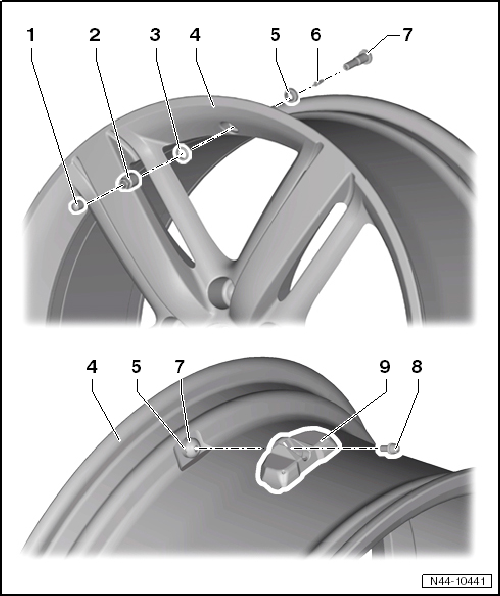
- Valve Cap
- Nut
- Individual component of -item 7-
- Tightening specification.
- Always replace if removed
- Washer
- Individual component of -item 7-
- Disc Wheel
- Tire mounting.
- Seal
- Individual component of -item 7-
- Valve Insert
- Replace at every tire change
Note
Never use brass valve inserts (corrosion!) Only use nickel valve inserts (silver).
- Metal Valve
- Supplied as a replacement part complete with bolt -item 8-
- Removing and Installing.
- Bolt
- Torx bolt (service version)
- Individual component of -item 7-
- 4 N·m
- Square screw with a flat head (vehicle before customer delivery)
- Tire Pressure Monitoring Sensor
- Left Front Tire Pressure Monitoring Sensor -G222-
- Right Front Tire Pressure Monitoring Sensor -G223-
- Left Rear Tire Pressure Monitoring Sensor -G224-
- Right Rear Tire Pressure Monitoring Sensor -G225-
- Removing and Installing on vehicles after customer delivery.
- Removing and Installing on vehicles before customer delivery.
Note
The tire pressure monitoring sensors expire after approximately 10 years.
Union Nut Tightening Specification
| Model, type | System | Country | Nm |
| All VW Vehicles | Direct measurement | all countries | 4 N·m |
| Audi A1, 8X | TPMS + indirect measuring → Note | USA and rest of the world | ------ |
| Audi A3, 8P | direct measuring, Siemens → Note | USA | 8 N·m |
| Audi A3, 8P | TPMS + indirect measuring → Note | Rest of the world | ------ |
| Audi A4, 8E | direct measuring, Beru → Note | USA and rest of the world | 4 N·m |
| Audi A4, 8K | direct measuring, Siemens → Note | USA | 8 N·m |
| Audi A4, 8K | TPMS + indirect measuring → Note | Rest of the world | ------ |
| Audi A5, 8T | direct measuring, Siemens → Note | USA | 8 N·m |
| Audi A5, 8T | TPMS + indirect measuring → Note | Rest of the world | ------ |
| Audi S5, 8T | direct measuring, Siemens → Note | USA | 8 N·m |
| Audi S5, 8T | TPMS + indirect measuring → Note | Rest of the world | ------ |
| Audi A5, S5 Cabrio 8F | direct measuring, Siemens → Note | USA | 8 N·m |
| Audi A5, S5 Cabrio 8F | TPMS + indirect measuring → Note | Rest of the world | ------ |
| Audi A6, 4B | direct measuring, Beru → Note | USA and rest of the world | 4 N·m |
| Audi A6, 4F | direct measuring, Beru → Note | USA and rest of the world | 4 N·m |
| Audi RS-6, 4F | direct measuring, Beru → Note | USA and rest of the world | 6 N·m |
| Audi A6, 4G | TPMS + indirect measuring → Note | USA and rest of the world | ------ |
| Audi A7, 4G | TPMS + indirect measuring → Note | USA and rest of the world | ------ |
| Audi A8, 4E | direct measuring, Beru → Note | USA and rest of the world | 4 N·m |
| Audi A8, 4H | TPMS + indirect measuring → Note | USA and rest of the world | ------ |
| Audi Q5, 8R | direct measuring, Siemens → Note | USA | 8 N·m |
| Q7, 4L | direct measuring, Beru → Note | USA and rest of the world | 4 N·m |
| Audi Q7, 4L-12-Cylinder | direct measuring, Beru → Note | USA and rest of the world | 4 N·m |
| Audi TT, 8J | direct measuring, Siemens → Note | USA | 8 N·m |
| Audi TT, 8J | TPMS + indirect measuring → Note | Rest of the world | ------ |
| Audi R8, 42 | direct measuring, Beru → Note | USA and rest of the world | 6 N·m |
Tire Pressure Monitoring Sensor, Removing and Installing
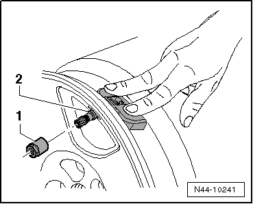
Tire Pressure Monitoring Sensor with Valve, Removing and Installing
Removing
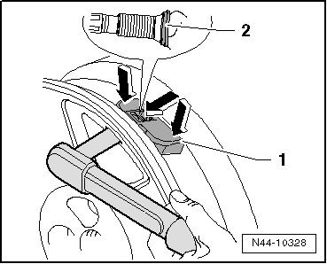
- Remove the union nut -1-.
- Remove Tire Pressure Monitoring Sensor-2- from rim well.
Installing
Caution
Clean the valve opening before installing the Tire Pressure Monitoring Sensor.
- Insert the Tire Pressure Monitoring Sensor-2- with new seal and sealing washer and press it on the spots marked with the -arrows- into the disc wheel (rim).
- Press the Tire Pressure Monitoring Sensor-2- on the spots marked with the -arrows- into the disc wheel (rim).
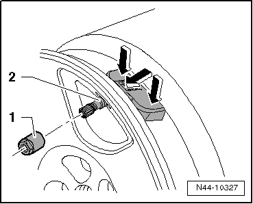
Screw on union nut -1- from outside onto tire pressure sensor.
- Press the Tire Pressure Monitoring Sensor-1- on the spots marked with the -arrows- into the rim and tighten the union nut to 8 N·m.
Caution
- Only tighten the union nut to the tightening specification.
- Sealing washer -2- becomes slightly deformed when doing this.
- The sealing washer can be installed one time only. At every installation, replace the sealing washer and rubber seal.
- Do not tighten the union nut again. This will damage the seal and it will leak.
Tire Pressure Monitoring Sensor without Metal Valve, Removing and Installing, Service Version
Special tools and workshop equipment required
- Torque Wrench -VAG1410-
Perform the Following:
Removing
- Remove the tire from the disc wheel.
See Which Version is Installed Before Starting Any Work.
I - Service Version
The tire pressure monitoring sensor is attached to the valve with an inner TORX screw -1- on the Service version.
If the service version is installed, the following repair procedure must be used.
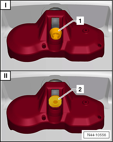
II - Vehicles Before Customer Delivery
The tire pressure monitoring sensor is attached to the valve with a square screw with a flat head -2- on vehicles before customer delivery.
If the production version is installed, the following repair procedure must be used.
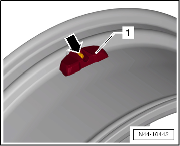
- Remove the screw -arrow- from the tire pressure monitoring sensor -1-.
- Counterhold metal valve using retainer (for example 2 mm spiral bore) while doing so.
Installing
Caution
Clean the valve opening before installing the Tire Pressure Monitoring Sensor.
- Press the tire pressure monitoring sensor -1- onto the disc wheel (rim) and tighten -arrow-.
- Counterhold metal valve using retainer (for example 2 mm spiral bore) while doing so.

Note
- Visually check the valve after installing it and make sure it is tight. The tire pressure monitoring sensor -1- must not have any play when it is installed and it must touch the supports in the rim bed.
- Do not tighten the valve again to the tightening specification after it has been installed.
Tire Pressure Monitoring Sensor without Valve, Removing and Installing, Vehicle Before Customer Delivery
Special tools and workshop equipment required
- Torque Wrench -VAG1410-
Perform the Following:
Removing
- Remove the tire from the disc wheel.
See which version is installed before starting any work.
I - Service Version
The tire pressure monitoring sensor is attached to the valve with an inner TORX screw -1- on the Service version.
If the service version is installed, the following repair procedure must be used.
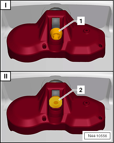
II - Vehicles Before Customer Delivery
The tire pressure monitoring sensor is attached to the valve with a square screw with a flat head -2- on vehicles before customer delivery.
If the production version is installed, the following repair procedure must be used.
- Turn the nut -1- counter-clockwise until it is possible to remove the tire pressure sensor -2-.
Note
- The whole valve turns when the nut it turned -1-.
- Both the tire pressure monitoring sensor and the metal valve must be replaced together. Refer to the Parts Catalog.
- Remove the metal valve.
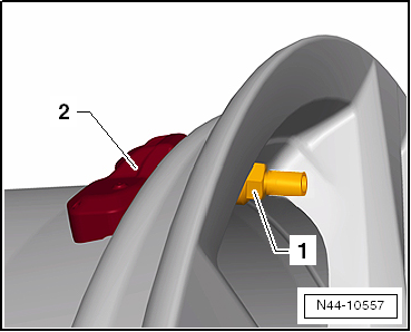
Installing
Note
- Both the tire pressure monitoring sensor and the metal valve must be replaced together. Refer to the Parts Catalog.
- The new metal valve is available with a new screw as a replacement set.
- Install the metal valve.
Caution
Clean the valve opening before installing the Tire Pressure Monitoring Sensor.
- Press the tire pressure monitoring sensor -1- onto the disk wheel (rim) and tighten the new screw -arrow-.
- Counterhold metal valve using retainer (for example 2 mm spiral bore) while doing so.
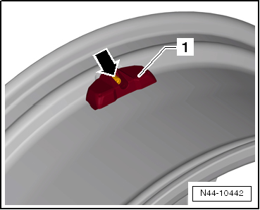
Note
- Visually check the valve after installing it and make sure it is tight. The tire pressure monitoring sensor -1- must not have any play when it is installed and it must touch the supports in the rim bed.
- Do not tighten the valve again to the tightening specification after it has been installed.
Tire Pressure Sensor and Metal Valve, Removing and Installing
Special tools and workshop equipment required
- Torque Wrench 1410 -VAG1410- and Torque Wrench 1331 5-50Nm -VAG1331-
- Place metal valve with rubber seal through rim from inside.
- Attach chamfered washer and union nut from outside and tighten by hand.
- Tighten the union nut.
Note
- If equipped handle the glued-on wheel trim carefully. Surface slightly scratched.
- Replace the damaged rim wheel trim.
1) TPMS direct measuring. The wheel electronics are installed inside the wheel on the metal valve; the tire pressure and temperature values are transmitted and evaluated periodically.
2) TPMS + indirect measuring. There are no wheel electronics installed inside the wheel. With the help of the ABS sensors, the TPMS compares the speed and rolling circumference of the individuals wheels. The loss of pressure is determined indirectly. If there is a change in the tire pressure, then the speed and the rolling circumference of wheel will also change.
3) TPMS indirect measuring. There are no wheel electronics installed inside the wheel. With the help of the ABS sensors, the TPMS compares the rolling circumference of the individual wheels. The loss of pressure is determined indirectly. If there is a change in the tire pressure, then the speed of the tire will also change.
- Secure against turning with counterhold -1- (for example, a 2 mm drill bit).
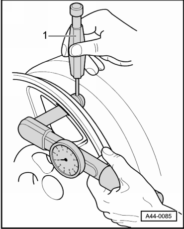
Not
- If equipped handle the glued-on wheel trim carefully. Surface slightly scratched.
- Replace the damaged rim wheel trim.
Beru Wheel Electronics Tire Pressure Monitoring Sensor, Removing and Installing
Overview, Beru System
WARNING
If tire sealant was used, then the wheel electronics on that particular wheel must be replaced.
WARNING
Damaged wheel electronics must be replaced.
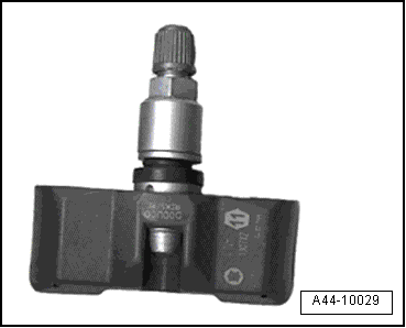
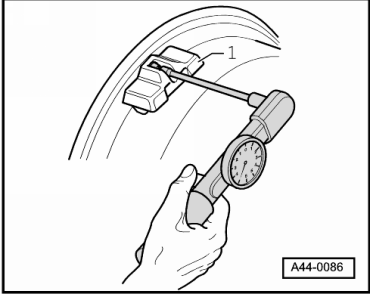
- Push the wheel electronics -1- into the bed.
- Install on the valve from the back with a microencapsulated screw -item 8-
Note
- Replace the microencapsulated screw.
- Tighten the microencapsulated screw to 4 N·m on all models.
Special tools and workshop equipment required
- Torque Wrench 1410 -VAG1410- and Torque Wrench 1410 Insert - Accessory Kit -VAG1410/1-
Siemens Wheel Electronics Tire Pressure Monitoring Sensor, Removing and Installing
WARNING
If tire sealant was used, then the wheel electronics on that particular wheel must be replaced.
- The Siemens wheel electronics does not have a microencapsulated screw.
- A union nut holds the wheel electronics in place inside the rim -item 2-
- The metal valve body serves as an antenna.
- The connection between the metal valve body to the wheel electronics must not get damaged.
WARNING
Counterhold the metal valve from the back by hand when pressing the wheel electronics into the bed on the rim. The connection between the metal valve to the wheel electronics must not get interrupted or damaged. Damaged wheel electronics must be replaced.
- Press the wheel electronics into the bed.
- Tighten the wheel electronics to the metal valve with the union nut.
Test yourself
A quick Volkswagen Tiguan quiz: every answer comes with an explanation and a link to the manual page.