Start-stop system
General description - Start-stop system
General description:
The start-stop system reduces fuel consumption by automatically switching off the engine during stationary phases and restarting it automatically when the driver wants to move off. Start-stop operation is activated automatically once the vehicle has been driven for approx. 4 seconds after moving off at a speed of at least 3 km/h.
The following control modules are involved in the start-stop system:
- Diagnostic interface for data bus -J533- in onboard power supply control module -J519-
- Engine control module -J623-
- Control module for ABS -J104-
Charging battery or jump starting vehicles with start-stop system:
When charging or jump-starting vehicles with start-stop system, observe the following: Using the charging cable, first connect the positive terminals; then connect the body ground. This ensures that the battery sensor is not bypassed. Connecting the battery directly at the negative terminal causes the battery sensor to be bypassed, so the battery data is not recorded by the sensor during charging. The battery condition values stored in the diagnostic interface for data bus would then no longer match the values of the charged battery.
Replacing the battery on vehicles with start-stop system:
Due to the higher cycle durability requirements, vehicles with start-stop system use a special starter battery.
When replacing the starter battery, make sure to use the correct spare part number in → ETKA (Electronic Parts Catalogue). Starter batteries for use in vehicles with start-stop system are identified by the marking "AGM" (Absorbent Glass Mat) or "EFB" (Enhanced Flooded Battery).
Fault detection and fault indication:
The start-stop system function is housed in the software of engine control module -J623-.
Engine control module -J623- is equipped with self-diagnosis, which facilitates fault finding.
For fault finding, use one of the systems described in the chapter "Vehicle diagnostic, measurement and information systems" in the "Guided fault finding" function.
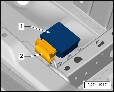
Voltage stabilizer -J532- is attached to the floor covering under the left front seat. Its task is to stabilize the high voltage fluctuations caused by start-stop operation to 12 volts for the onboard power supply.
Effects if the voltage stabilizer fails:
If the voltage stabilizer is faulty, devices such as radio, radio navigation or telephone will perform a reset if their own power supply is insufficient when the starter is operated. If the mentioned electrical consumers reset with every engine start during start-stop operation, this indicates a faulty voltage stabilizer. There is currently no direct entry for a voltage stabilizer malfunction in the event memory of the diagnostic interface or onboard power supply control module. If the radio, radio navigation and telephone have failed together, first check the voltage stabilizer fuse.
Removing and installing voltage stabilizer
Removing
- Slide the driver's seat to the rearmost position.
- Detach the hook-and-loop fastener of voltage stabilizer -J532--1- from the floor covering.
- Unlock and pull off connector -2- and remove voltage stabilizer -J532- from the vehicle.
Installing
Installation is performed in the reverse order of removal, observing the following:
- When installing, first attach and lock the connector, then secure the voltage converter at its original installation location on the floor covering with the hook-and-loop strap.