Control unit and hydraulic unit
Connecting brake lines to hydraulic unit
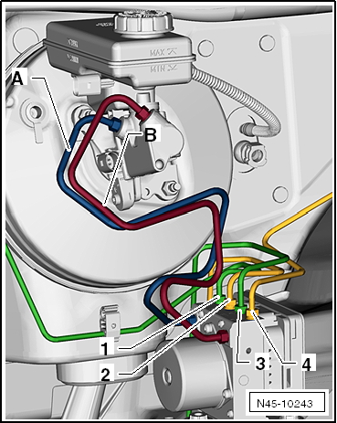
Connecting brake lines to hydraulic unit, left-hand drive
- Push-rod piston circuit of master cylinder to hydraulic unit
- Floating piston circuit of master cylinder to hydraulic unit
- Hydraulic unit to front right brake caliper
- Hydraulic unit to rear left wheel brake cylinder
- Hydraulic unit to rear right wheel brake cylinder
- Hydraulic unit to front left brake caliper
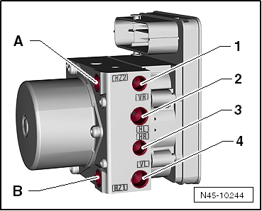
Marking on hydraulic unit:
- Hydraulic unit to push-rod piston circuit of master cylinder
- Marking on hydraulic unit -HZ2-
- Hydraulic unit to floating piston circuit of master cylinder
- Marking on hydraulic unit -HZ1-
- Hydraulic unit to front right brake caliper
- Marking on hydraulic unit -VR-
- Hydraulic unit to rear left brake caliper/wheel brake cylinder
- Marking on hydraulic unit -HL-
- Hydraulic unit to rear right brake caliper/wheel brake cylinder
- Marking on hydraulic unit -HR-
- Hydraulic unit to front left brake caliper
- Marking on hydraulic unit -VL-
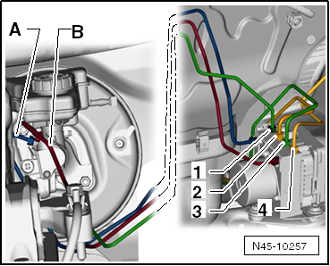
Connecting brake lines to hydraulic unit, right-hand drive
- Push-rod piston circuit of master cylinder to hydraulic unit
- Floating piston circuit of master cylinder to hydraulic unit
- Hydraulic unit to front right brake caliper
- Hydraulic unit to rear left wheel brake cylinder
- Hydraulic unit to rear right wheel brake cylinder
- Hydraulic unit to front left brake caliper
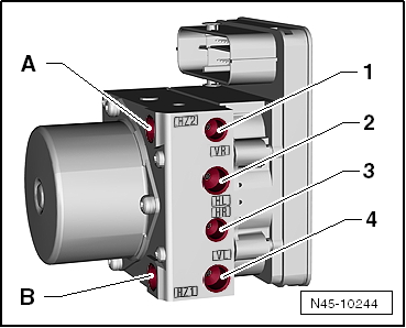
Marking on hydraulic unit:
- Hydraulic unit to push-rod piston circuit of master cylinder
- Marking on hydraulic unit -HZ2-
- Hydraulic unit to floating piston circuit of master cylinder
- Marking on hydraulic unit -HZ1-
- Hydraulic unit to front right brake caliper
- Marking on hydraulic unit -VR-
- Hydraulic unit to rear left brake caliper/wheel brake cylinder
- Marking on hydraulic unit -HL-
- Hydraulic unit to rear right brake caliper/wheel brake cylinder
- Marking on hydraulic unit -HR-
- Hydraulic unit to front left brake caliper
- Marking on hydraulic unit -VL-
Removing and installing control unit and hydraulic unit
Removing and installing control unit and hydraulic unit, left-hand drive
Required Special Tools, Test and Measuring Equipment and Auxiliary Items
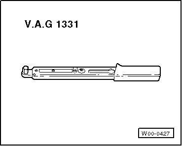
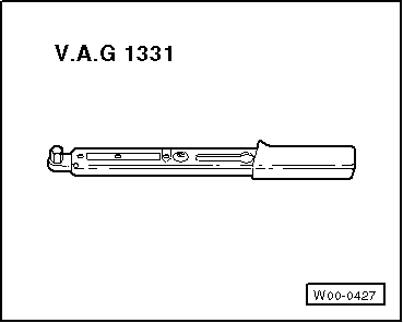
- Torque Wrench -V.A.G 1331-
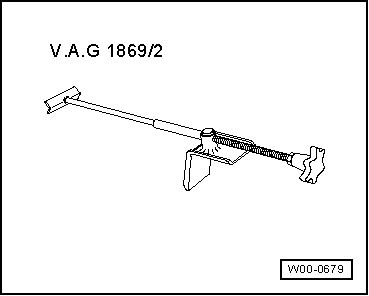
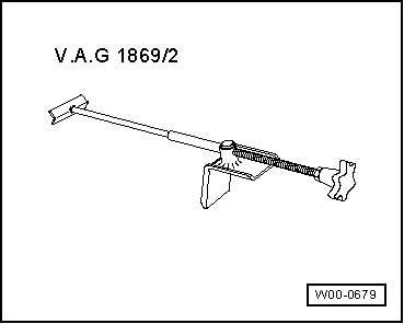
- Brake pedal depressor -V.A.G 1869/2-
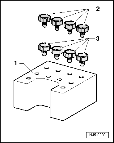
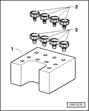
Sealing plug, repair kit, part no. 1H0 698 311 A
Installation location:
The control unit is bolted to the hydraulic unit and is located in the engine compartment on the left, under the battery carrier.

WARNING!
Brake lines in the area of the hydraulic unit must not be bent!
Removing:
- Read out and note the existing control unit coding.
- On vehicles with coded radio, observe the radio coding; ask the customer if necessary.
- Remove the battery → Electrical System.
- Remove the engine control module with bracket and set it aside → 3-cyl. injection engine, toothed belt drive (4-valve).
- Remove the battery tray → Electrical system.
- Remove the air filter housing → 3-cyl. injection engine, toothed belt drive (4-valve).
- Lay out enough lint-free rags in the area of the engine and the transmission.
- Extract as much brake fluid as possible from the brake fluid reservoir with the brake filling and bleeding unit -VAS 5234-.
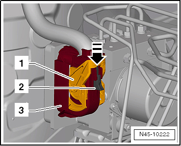
- Press the locking slider -2- down in the -arrow direction-.
- Then press the locking clip -1- down in the -arrow direction- to unlock connector -3-.
- Pull the connector off the control module towards the front.
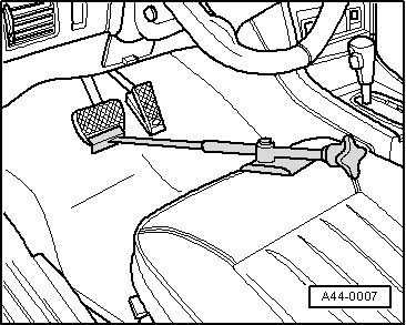
- Install the brake pedal depressor -V.A.G 1869/2-.
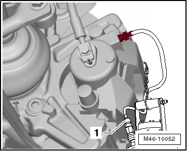
- Push the bleeder hose of bleeder bottle -1- onto the bleeder valve of the front left brake caliper.
- Open the bleeder valve.
- Push the bleeder hose of the bleeder bottle onto the bleeder valve of the rear left wheel brake cylinder.
- Open the bleeder valve.
- Press the brake pedal at least 60 mm with the brake pedal depressor -V.A.G 1869/2-.
- Close the bleeder valves at the front left and rear left.
- Do not remove the brake pedal depressor -V.A.G 1869/2-.
- Lay out enough lint-free rags under the control module and the hydraulic unit.
Make sure no brake fluid gets onto the contacts.
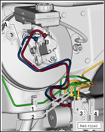
- Mark the brake lines from the hydraulic unit -A and B- to the master brake cylinder.
- Then unscrew brake lines -A and B- from the master brake cylinder and the hydraulic unit and immediately seal them with the sealing plugs from repair kit ET.- No. 1H0 698 311 A.
- Mark the remaining brake lines (to the brake calipers) -1 to 4-, unscrew them from the hydraulic unit and immediately seal them with sealing plugs from repair kit ET.- No. 1H0 698 311 A.
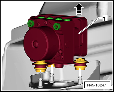
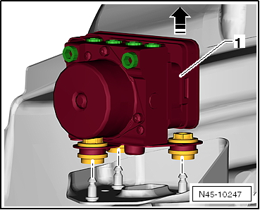
- Pull the ABS hydraulic unit -N55--1- together with the ABS control module -J104- and the bracket upwards in the -arrow direction- off the weld studs.
Installing:

Note
- Only remove the sealing plugs from the new hydraulic unit when the corresponding brake line is installed.
- If the sealing plugs are removed from the hydraulic unit beforehand, brake fluid may run out, so that adequate filling and bleeding can no longer be ensured.
- When installing, make sure the damper rubbers sit correctly in the bracket.
- Install in reverse order.
- Remove the brake pedal depressor -V.A.G 1869/2-.
- Bleed the brake system.
- Code the ABS control module -J104- with the vehicle diagnostic tester in "Guided Fault Finding".
- Code the radio.
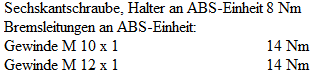
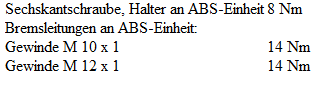
Tightening torques:
Remove and install control module and hydraulic unit, right-hand drive
Required Special Tools, Test and Measuring Equipment and Auxiliary Items
- Torque Wrench -V.A.G 1331-
- Brake pedal depressor -V.A.G 1869/2-
Sealing plug, repair kit, part no. 1H0 698 311 A
Installation location:
The control unit is bolted to the hydraulic unit and is located in the engine compartment on the left, under the battery carrier.

WARNING!
Brake lines in the area of the hydraulic unit must not be bent!
Removing:
- Read out and note the existing control unit coding.
- On vehicles with coded radio, observe the radio coding; ask the customer if necessary.
- Remove the battery → Electrical System.
- Remove the engine control module with bracket and set it aside → 3-cyl. injection engine, toothed belt drive (4-valve).
- Remove the battery tray → Electrical system.
- Remove the air filter housing → 3-cyl. injection engine, toothed belt drive (4-valve).
- Lay out enough lint-free rags in the area of the engine and the transmission.
- Extract as much brake fluid as possible from the brake fluid reservoir with the brake filling and bleeding unit -VAS 5234-.
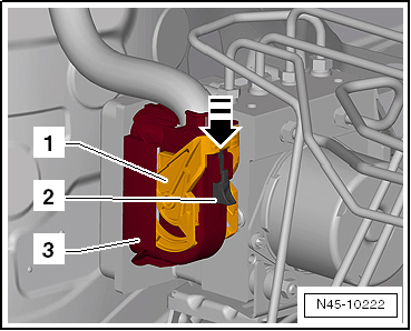
- Press the locking slider -2- down in the -arrow direction-.
- Then press the locking clip -1- down in the -arrow direction- to unlock connector -3-.
- Pull the connector off the control module towards the front.
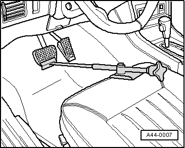
- Install the brake pedal depressor -V.A.G 1869/2-.
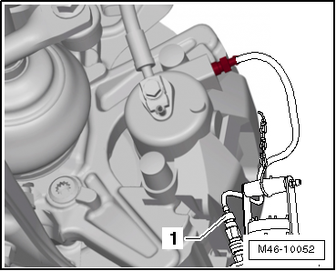
- Push the bleeder hose of bleeder bottle -1- onto the bleeder valve of the front left brake caliper.
- Open the bleeder valve.
- Push the bleeder hose of the bleeder bottle onto the bleeder valve of the rear left wheel brake cylinder.
- Open the bleeder valve.
- Press the brake pedal at least 60 mm with the brake pedal depressor -V.A.G 1869/2-.
- Close the bleeder valves at the front left and rear left.
- Do not remove the brake pedal depressor -V.A.G 1869/2-.
- Lay out enough lint-free rags under the control module and the hydraulic unit.
Make sure no brake fluid gets onto the contacts.
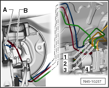
- Mark the brake lines from the hydraulic unit -A and B- to the master brake cylinder.
- Unclip the brake lines from the bracket on the bulkhead.
- Then unscrew brake lines -A and B- from the hydraulic unit and immediately seal them with the sealing plugs from repair kit ET.- No. 1H0 698 311 A.
- Mark the remaining brake lines (to the brake calipers) -1 to 4-, unscrew them from the hydraulic unit and immediately seal them with sealing plugs from repair kit ET.- No. 1H0 698 311 A.
- Pull the ABS hydraulic unit -N55--1- together with the ABS control module -J104- and the bracket upwards in the -arrow direction- off the weld studs.
Installing:

Note
- Only remove the sealing plugs from the new hydraulic unit when the corresponding brake line is installed.
- If the sealing plugs are removed from the hydraulic unit beforehand, brake fluid may run out, so that adequate filling and bleeding can no longer be ensured.
- When installing, make sure the damper rubbers sit correctly in the bracket.
- Install in reverse order.
- Remove the brake pedal depressor -V.A.G 1869/2-.
- Bleed the brake system.
- Code the ABS control module -J104- with the vehicle diagnostic tester in "Guided Fault Finding".
- Code the radio.
Tightening torques:
Assembly Overview
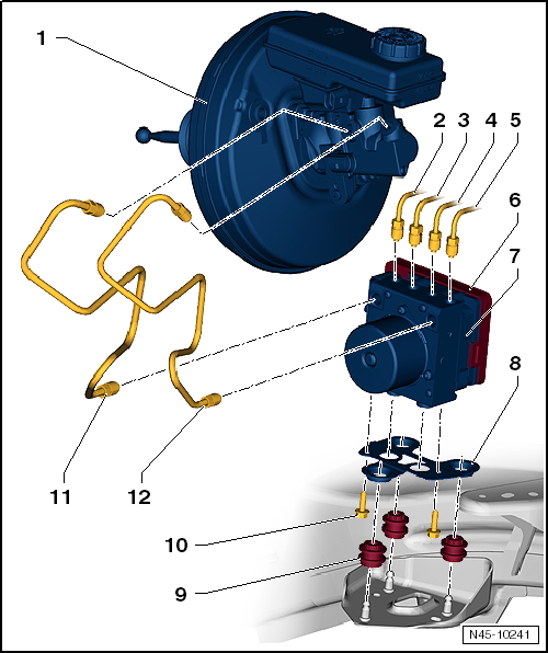
- Brake booster
- Remove and install
- Brake line, 14 N·m
- to front right brake caliper
- Marking on hydraulic unit -VR-
- with thread M10 x 1
- Brake line, 14 N·m
- to rear left wheel brake cylinder
- Marking on hydraulic unit -HL-
- with thread M12 x 1
- Brake line, 14 N·m
- to rear right wheel brake cylinder
- Marking on hydraulic unit -HR-
- with thread M10 x 1
- Brake line, 14 N·m
- to front left brake caliper
- Marking on hydraulic unit -VL-
- with thread M12 x 1
- ABS control module -J104-
- Remove and install ABS hydraulic unit -N55- with ABS control module -J104-
- ABS hydraulic unit -N55-
- ABS return pump -V39- and valve block must not be separated from each other
- When replacing the hydraulic unit, always seal the old part with the sealing plugs from repair kit -1H0 698 311 A-.
- Remove and install ABS hydraulic unit -N55- with ABS control module -J104-
- Bracket
- Assignment → Electronic Parts Catalog "ETKA"
- Damper rubber
- Hex bolt, 8 N·m
- Brake line, 14 N·m
- Master brake cylinder/push-rod piston circuit to hydraulic unit
- Marking on hydraulic unit -HZ2-
- with thread M12 x 1
- Brake line, 14 N·m
- Master brake cylinder/floating piston circuit to hydraulic unit
- Marking on hydraulic unit -HZ1-
- with thread M12 x 1