General Information
The following variants of TRW ABS are possible:
- ABS
- ABS/ESP
The ABS brake system is split diagonally. Brake boost is provided pneumatically by the vacuum brake booster.
Faults in the ABS do not affect the brake system or brake boost. The conventional brake system remains functional without ABS. Changed braking behavior must be expected. After the ABS warning lamp illuminates, the rear wheels may lock up prematurely when braking!
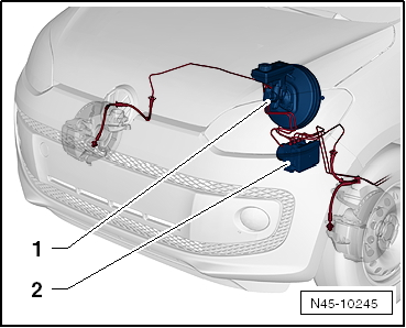
ABS layout in left-hand drive vehicle:
- Brake booster
- Hydraulic unit and control unit
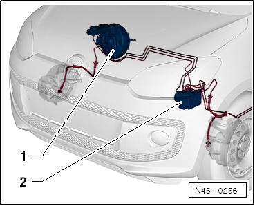
ABS layout in right-hand drive vehicle:
- Brake booster
- Hydraulic unit and control unit
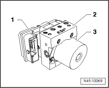
Control unit -1- and hydraulic unit -2- form one unit. The hydraulic pump -3- must not be separated from the hydraulic unit.
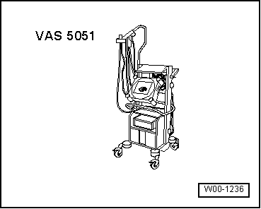
Vehicle diagnosis, measurement and information system
Connect -vehicle diagnostic tester- and select functions.
Required special tools, testers and equipment, and auxiliary items
- Vehicle diagnostic tester

WARNING!
- During a test drive, always secure test and measuring equipment on the rear seat.
- While driving, only a passenger may operate these devices.
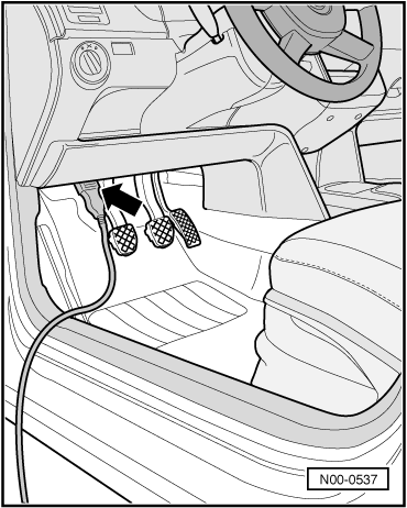
- Connect the plug of the diagnostic lead to the diagnostic connector -arrow-.
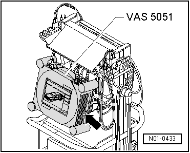
- Switch on the -vehicle diagnostic tester- -arrow-.
The -vehicle diagnostic tester- is ready for operation when it shows the touch fields of its operating modes.
- Switch ignition on.
- Touch Guided Fault Finding on the screen.
- Select in sequence:
- Make
- Type
- Model year
- Variant
- Engine code letters
- Confirm the entered data.
Wait until the tester has queried all control modules installed in the vehicle.
- Press Jump and select the function "Function/component selection".
- Select "Chassis" on the display.
- Select "Brake system" on the display.
- Select the displayed "01-Self-diagnosis capable systems..." on the display.
- Select the displayed "Anti-lock brake system..." on the display.
- Select the displayed "Function" on the display.
All possible functions of the anti-lock brake system installed in the vehicle are now displayed.
- Select the desired function on the display.
Repair notes for ABS work
- Before repairing the anti-lock brake system, determine the cause of the damage using "Guided Fault Finding".
Guided Fault Finding is performed with the Vehicle Diagnostic, Measurement and Information System -VAS 5051-.
- Disconnect the battery earth strap with the ignition switched off.
- Before electric welding work → General notes; Body repair, body assembly work must be observed.
- When handling brake fluid, observe the applicable safety precautions and notes.
- After work that required opening the brake system, bleed the brake system with the Brake Filling and Bleeding Unit -VAS 5234-.
- During the final road test, make sure that at least one controlled braking is performed (pulsing must be felt at the brake pedal).
- When working on the anti-lock brake system, maximum cleanliness is required. Under no circumstances use mineral oil-based auxiliary materials such as oils, greases, etc.
- Thoroughly clean connection points and their surroundings before disconnecting, but do not use aggressive cleaning agents such as brake cleaner, petrol, thinner or similar.
- Place removed parts on a clean surface and cover them.
- After disconnecting the control module from the hydraulic unit, use the transport protection for the valve domes.
- Carefully cover or seal opened components if the repair is not carried out immediately. (Use sealing plugs, Repair Kit 1 H0 698 311 A)
- Do not use lint-producing rags.
- Remove replacement parts from the packaging only immediately before installation.
- Use only original packaged parts.
- Do not work with compressed air and do not move the vehicle when the system is open.
- During painting work, the electronic control module may be exposed briefly to max. 95 °C and for a longer period (approx. 2 hours) to max. 85 °C. Make sure no brake fluid flows into the connectors.