Technical Data
Assessment of Accident Vehicles
Checklist for assessing the chassis of accident vehicles
When repairing load-bearing and wheel-guiding components on accident vehicles, damage to the chassis may go undetected. These undetected damages may later lead to serious consequential damage during driving. Therefore, on accident vehicles, the listed components must be checked in the described manner and sequence, regardless of any wheel alignment to be performed. If no deviations from the nominal values have been found during a wheel alignment, there is no deformation of the chassis.
Visual and functional check of the steering system
- Visually check for deformation and cracks
- Check play of tie rod joints and steering gear
- Visually check bellows and grease boots for damage
- Check electrical and hydraulic lines and hoses for chafing, cuts and kinks
- Check hydraulic lines, screw connections and steering gear for leaks
- Check steering gear and lines for secure mounting
- Check proper function over the full steering range by turning the steering from lock to lock. The steering wheel must turn with constant actuating force and without binding.
Visual and functional check of the chassis
The sequence of the following inspection steps must be observed!- Check all components shown in the assembly overviews for deformation, cracks and other damage.
- Replace damaged parts
- Measure the vehicle on a wheel alignment rig approved by Volkswagen AG
Visual and functional check of wheels and tyres
- Check for radial and lateral runout and imbalance.
- Check tyres for cuts and impact damage in the tread and on the sidewalls.
- Check tyre pressure; for tyre pressure, see the tyre pressure label in the fuel filler flap.
If the rim and/or tyre is damaged, replace the tyre. This also applies if the accident circumstances and the vehicle damage suggest possible damage that is not visible.
Another decision criterion is tyre age: tyres should not be older than 6 years.
In case of doubt, always apply the following:
If a safety risk cannot be ruled out, the tyre(s) must be replaced.Entire vehicle
Also check other vehicle systems, such as:
- Brake system including ABS
- Exhaust system and occupant protection by visual and functional check
Test and adjustment values and related notes can be found in the respective repair manuals/ELSA.
The inspection described here for accident vehicles relates to the chassis. It does not claim to be complete for the entire vehicle.
Electronic vehicle systems
Safety-relevant systems, such as: ABS/EDS; airbag; electronically controlled chassis systems; electromechanical, electrohydraulic steering and other driver assistance systems must be queried for any stored fault messages using the → vehicle diagnostic tester. If faults have been stored in the event memory of the mentioned systems, they must be repaired in accordance with the specifications in the repair manual/ELSA. After repair, the affected systems must be checked again for event memory entries to ensure that the function is guaranteed.
General Information
Types of tyres
Information on wheels, tyres and snow chains can be found in the → Wheels, Tyres guide and in the → Wheels, Tyres - General Information guide.
Repair notes
Raising wheel suspension to unladen position on vehicles with coil springs
Raising wheel suspension to unladen position on vehicles with coil springs, front axle

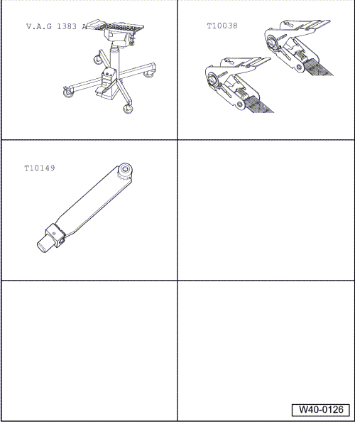
Required Special Tools, Test and Measuring Equipment and Auxiliary Items
- Engine and Transmission Hoist -V.A.G 1383 A-
- Tension strap -T10038-
- Support -T10149-

Caution!
All bolts on chassis components with rubber-metal bushings must always be tightened in unladen position (vehicle without load).
Rubber-metal bushings have a limited range of rotation.
Therefore, axle components with rubber-metal bushings must be brought into a position corresponding to the position during driving (unladen position) before tightening.
Otherwise, the rubber-metal bushing will be preloaded, which would result in a shorter service life.
By raising the corresponding wheel suspension with the engine and transmission jack -V.A.G 1383 A- and the support -T10149-, this position can be simulated on the lift.
Before raising the corresponding wheel suspension, the vehicle must be secured to the support arms of the lift with tensioning straps -T10038-.

WARNING!
If the vehicle is not secured, there is a risk that it may slip off the lift!
- Turn the wheel hub until one of the wheel bolt holes is at the top.
- Install adapter -T10149- on the wheel hub with a wheel bolt.
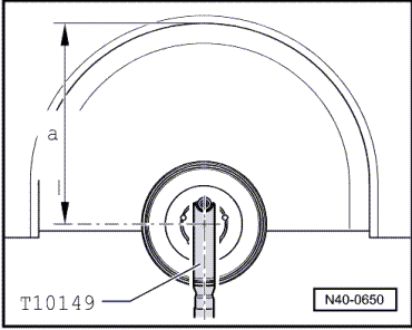
The affected bolts/nuts may only be tightened when dimension -a- between the center of the wheel hub and the lower edge of the wheel housing has been reached.
Dimension -a- depends on the ride height of the installed suspension:
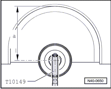
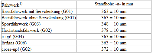
1) The vehicle data carrier shows which suspension is installed in the vehicle. The suspension is identified by a PR number. Assignment of PR number to the corresponding suspension.
- Raise the wheel bearing housing with engine and transmission jack -V.A.G 1383 A- until dimension -a- is reached.

WARNING!
- Do not raise or lower the vehicle while the engine and transmission jack is under the vehicle.
- Do not leave the engine and transmission jack under the vehicle longer than necessary.
- Tighten the affected bolts/nuts.
- Lower the wheel bearing housing.
- Pull the engine and transmission jack -V.A.G 1383 A- out from under the vehicle.
- Remove adapter -T10149-.
Raising wheel bearing to unladen position on vehicles with coil spring, rear axle
Required Special Tools, Test and Measuring Equipment and Auxiliary Items
- Engine and Transmission Hoist -V.A.G 1383 A-
- Tension strap -T10038-
- Support -T10149-

Caution!
All bolts on chassis components with rubber-metal bushings must always be tightened in unladen position (vehicle without load).
Rubber-metal bushings have a limited range of rotation.
Therefore, axle components with rubber-metal bushings must be brought into a position corresponding to the position during driving (unladen position) before tightening.
Otherwise, the rubber-metal bushing will be preloaded, which would result in a shorter service life.
By raising the axle on one side with the engine and transmission jack -V.A.G 1383 A- and adapter -T10149-, this position can be simulated on the lift.
Before raising the axle on one side, the vehicle must be secured on both sides to the lift arms with ratchet straps -T10038-.

WARNING!
If the vehicle is not secured, there is a risk that it may slip off the lift!
- Turn the wheel hub until one of the wheel bolt holes is at the top.
- Install adapter -T10149- with a wheel bolt.
Bolting may only be carried out when dimension -a- between the center of the wheel hub and the lower edge of the wheel housing, measured before installation, has been reached!
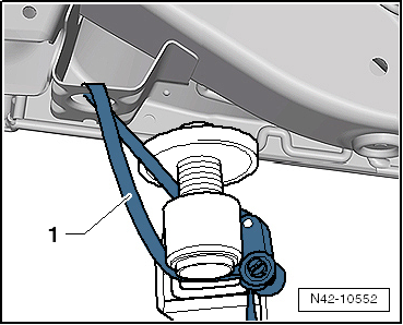
Measure dimension -a-
Dimension -a- depends on the ride height of the installed suspension:
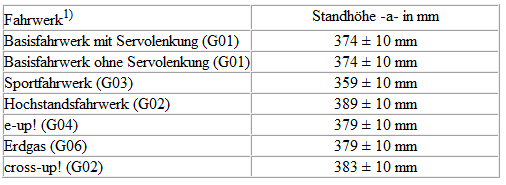
1) The vehicle data carrier shows which suspension is installed in the vehicle. The suspension is identified by a PR number. Assignment of PR number to the corresponding suspension.
- Raise the wheel bearing housing with the engine and transmission jack until dimension -a- is reached.

WARNING!
- Do not raise or lower the vehicle while the engine and transmission jack is under the vehicle.
- Do not leave the engine and transmission jack under the vehicle longer than necessary.
- Tighten the affected bolts/nuts.
- Lower the wheel bearing housing.
- Pull the engine and transmission jack out from under the vehicle.
- Remove adapter -T10149-.
General repair notes
For a proper and successful steering gear repair, utmost care and cleanliness, as well as flawless tools, are an important prerequisite. Of course, the generally accepted basic safety rules also apply to repairs.
A number of generally valid notes for individual repair procedures, otherwise repeated at many points in the repair manual, are summarized here. They apply to this repair manual.
A description of the design and function of this steering system can be found in → No. 500.
Steering gear
- Thoroughly clean the connection points and their surroundings, then loosen them.
- Place removed parts on a clean surface and cover them to prevent contamination. Use foil and paper. Do not use lint-producing rags!
- Only install clean parts: remove replacement parts from the packaging immediately before installation.
- Use only lubricants and sealants designated with part numbers.
- Carefully cover or seal open components if the repair is not carried out immediately.
Seals, sealing rings
- Always replace sealing rings and seals.
- After removing seals, check the contact surfaces on housings or shafts for burrs and damage, and remove any found.
- Remove all residue of liquid sealant from the sealing surfaces. No sealant residue may get into the steering gear housing.
Bolts, nuts
- Loosen and tighten the bolts or fastening nuts of covers and housings in a crosswise sequence.
- Do not tilt particularly sensitive parts, e.g. servo motor with control module. Loosen and tighten them in stages in a crosswise sequence.
- Tightening torques are specified for non-oiled bolts and nuts.
- Always replace self-locking bolts and nuts.

Electrical components
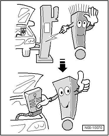
You have probably received an electric shock when touching metal objects. The reason is the electrostatic charge of the human body. Touching electrical components of the steering gear can cause malfunctions due to this charge.
- Touch a grounded object, for example a water pipe or a lift, before working on electrical components. Do not touch the plug contacts directly.
Repairing damaged threads in side member (subframe to body)
Repairing the thread in the weld nuts in the side member is possible under certain conditions.