Technical Data
Notes on operating mobile phones and two-way radios
General Information
Mobile phones or portable two-way radios must not be operated inside the vehicle without a separate external antenna
- Radio remote controls (e.g. for garage door openers) and cordless devices (e.g. keyboards or PC mice) may only be operated in the vehicle if the transmission power of the device is no more than 100 mW.
- Mobile two-way radios require an "e-marking" (applies to Europe only).
- Mobile phones or other radio transmitters (business equipment) that are not original vehicle equipment must bear a "CE marking" (applies to Europe only).
- Be sure to observe the operating instructions and installation notes of the manufacturers for mobile phones, two-way radios and antennas.
- The optimum range of the devices is only achieved with an external antenna.
- If telephone and radio systems are installed correctly, there is no risk of interference with safety systems such as ABS or airbags. However, this requires that no changes are made to their installations. Routing cables parallel to such systems must be avoided.
- Using mobile phones and two-way radios without an external antenna, or with an incorrectly installed external antenna, can cause excessive electromagnetic fields inside the vehicle interior.
In this case, health impairments and malfunctions of the vehicle electronics cannot be ruled out.
Installation and operation of two-way radios with a transmission power above 10 watts for the radio services listed in the table is only permitted under the following conditions:
- The transmission power at the antenna base point (see manufacturer's specifications for the device) must not exceed the respective maximum values.
- The antenna installation locations listed in the table must not be deviated from.
Table of transmission powers and antenna installation locations.
Notes on performing installation work
Before starting installation work, the batteries must be disconnected! → Electrical System; Starter, Power Supply; Battery; Disconnecting and Connecting the Battery.
The valid wiring diagram must be used → Wiring diagrams, Electrical Troubleshooting and Installation Locations.
For removing and installing trim panels, see ⇒ Repair Guide Body Installation Work Interior or ⇒ Repair Guide Body Installation Work Exterior.
The operating instructions and installation notes of the manufacturers for mobile phones, two-way radios and antennas must be observed.
Wiring harnesses must be secured with cable ties. Plug connectors must be fitted with foam tubes to prevent rattling.
Transmission power and possible installation locations
Volkswagen permits the installation and operation of transmitting radio equipment as long as the transmission powers listed in the table at the antenna base point are not exceeded. Mandatory antenna installation locations are also shown in the table.
The limit values according to VDE 0848 Part 2 (maximum permissible field strength for personal protection) must be observed, if necessary by reducing the transmission power.
Power supply
When retrofitting a transceiver in the vehicle, the battery is used to connect the positive and negative lines.
The wiring harness must additionally be made:
- Positive-side power supply through a red line with a 2.5 mm2 cross-section.
- Negative-side power supply through a brown line with a 2.5 mm2 cross-section.
The positive line must be protected with a fuse in the immediate vicinity of the battery. For this purpose, a fuse holder must be mounted next to the battery. Both lines must be covered with insulating tubing.
Suitable connectors must be fitted on the battery side.
On the device side, proceed according to the device operating instructions.
The additional wiring harness must be routed separately from the vehicle wiring, with a minimum distance of 10 cm.

Note
- Some telephone systems and two-way radios additionally require terminal 15 (ignition). In this case, a black wire with a 1.5 mm2 cross-section must be routed from the transceiver to terminal 15a. → Wiring diagrams, Electrical Troubleshooting and Installation Locations
- When routing the line connections, make sure that the line connections are not routed parallel to the series wiring.
Antenna and antenna cable
A shielded cable must be used between the transceiver and the antenna. The shield must be connected on the device side and on the antenna side.
At the same time, make sure there is a good and permanent ground connection from the antenna base lead to the vehicle body.
The transmitter system must be operated in a tuned state to avoid interference on the antenna cable. For safety, check and tune the system by means of a power measurement.
Other additional installations
Installing other electronic equipment, such as office equipment (e.g. TV, fax) or household equipment (e.g. electric cool box), is only permitted if these devices carry a CE mark or an e-mark (applies to Europe only).
The power supply must also be routed via a separate wiring harness and be fitted with a fuse.
Overview of battery, transceiver, fuse and wiring harness
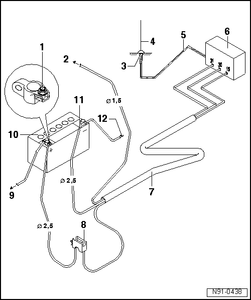
- Positive connection
- red wire with suitable connector
- to terminal 15a
- Connection to terminal 15a: → Wiring diagrams, electrical fault finding and installation locations
- make sure this wire is fused
- Fuse rating max. 15 A
- Antenna ground
- make sure there is a good ground connection to the body
- the antenna installation location must be provided with suitable corrosion protection
- Transceiver antenna
- Installation locations: ⇒ Table page
- shielded antenna cable
- cable with coaxial connector
- Transceiver, telephone or radio
- Wiring harness
- Positive-side power supply through a red wire with 2.5 mm2 cross-section
- Negative-side power supply through a brown wire with 2.5 mm2 cross-section
- if necessary, wire to terminal 15a through a black wire with 1.5 mm2 cross-section
- Fuse holder
- install in the immediate vicinity of the battery
- to the starter
- Battery
- Installation position in the engine compartment
- Negative wire
- Body ground
Transmission power and antenna installation locations
Up►

Note
Due to legal regulations, installing antennas on bumpers is no longer permitted. This improves pedestrian accident protection.

1) PEAK = max. carrier power (peak envelope power)
2) Eff. = effective transmission power

Note
- Deviations from these specifications (antenna location, frequency, power) are only permitted in exceptional, justified cases, after an individual case review by the EMC Center of Volkswagen AG in Wolfsburg.
- EMC = electromagnetic compatibility
Interference suppression measures
Implementation of interference suppression measures
All electrical consumers in the vehicle are interference-suppressed as standard.
These are sensors, actuators and electric motors, as well as the controllers in control units that could cause high-frequency interference.
For interference suppression, electrical components such as capacitors, coils and diodes are built directly into the electrical components.
Interference suppression components are also built into the connector housings of electrical consumers.
The earth straps previously used for interference suppression purposes are no longer used, because the interference suppression measures are applied close to the interference sources.