Technical Data
Safety Information
Safety precautions when working on vehicles with start-stop system

WARNING!
Risk of injury from automatic engine start on vehicles with start-stop system
- When working on the vehicle, deactivate the start-stop system. Switch off ignition.
- Switch on ignition briefly only when necessary.
Identification
Transmission identification
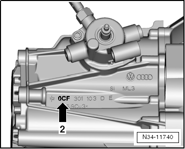
Code letters and production date -arrow 1- Manual transmission 0CF -arrow 2-
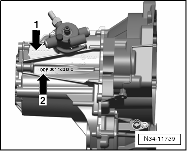
Manual transmission 0CF -arrow 2-
Transmission code letters and production date
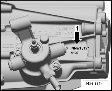
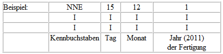
Additional data provides information on the production plant.

Note
The transmission code letters are also listed on the vehicle data carrier.
Repair notes
General repair notes
For a proper and successful transmission repair, the greatest possible care and cleanliness as well as flawless tools are essential. Of course, the generally applicable basic safety rules also apply to all repair work.
A number of generally valid notes for individual repair procedures - otherwise listed repeatedly at many points in the repair manual - are summarized here. They apply to this repair manual.
Special tools
Overview of the special tools used in the repair manual → Workshop equipment and special tools.
Transmission
- When installing the manual transmission, make sure the locating sleeves between engine and transmission are correctly seated.
- When installing bearing brackets and press-fitted components, clean the contact surfaces. Contact surfaces must be free of wax and grease.
- Assign screws and other components using the → Electronic Parts Catalog (ETKA).
- When repairing the manual transmission, top up the transmission oil.
Seals, sealing rings
- Thoroughly clean mating surfaces and apply sealant -AMV 188 200 03-.
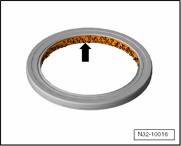
- Before installing radial shaft seals, fill the space between the sealing lips halfway with sealing grease -G 052 128 A1- -arrow-.
- The open side of the seal rings faces the fluid to be sealed.
- Lightly oil O-rings before inserting them to avoid pinching the rings during installation.
Sealants
- Thoroughly clean housing mating surfaces before applying sealing paste.
- Apply sealing paste -AMV 188 200 03- evenly and not too thick.
- No sealing paste must get into breather holes.
Retaining rings
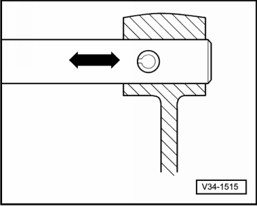
- Replace retaining rings.
- Do not overstretch retaining rings.
- Retaining rings must seat on the bottom of the groove.

- Replace tension sleeves. Installation position: slot running in line with the direction of force.
Bolts, nuts
- Loosen and tighten fastening screws or nuts of covers and housings in a crisscross pattern.
- Do not tilt particularly sensitive parts - e.g. clutch pressure plates - and loosen and tighten them in stages in a crisscross pattern.
- Tightening torques are specified for non-oiled bolts and nuts.
- Replace self-locking screws and nuts after removal.
- For all threaded connections, make sure that contact surfaces as well as screws and nuts are waxed only after installation, if necessary.
- Clean all threaded holes into which self-locking screws are screwed with a thread tap to remove residue of the locking agent. Otherwise there is a risk that the screws will break off on renewed removal.
- Check the correct thread pitch so that the correct thread tap is used for cleaning and the thread is not damaged.
Bearing
- Install all bearings with transmission oil.
- Install new tapered roller bearings as supplied and do not oil them additionally.
- Place needle bearings with the marked side (greater sheet metal thickness) facing the driving-in mandrel.
- Replace tapered roller bearings located on one shaft together and use products from one manufacturer.
- Heat bearing inner races to approx. 100 ºC with induction heater -VAS 6414- for installation.
- Do not mix up outer and inner races of bearings of the same size; bearings are matched sets.
Shims
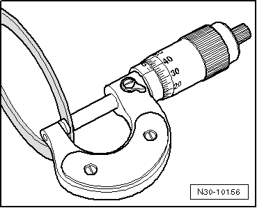
- Measure shims at several points with a micrometer. Due to varying tolerances, the required shim thickness can be measured precisely.
- Check for burrs or damage.
- Install only flawless shims.
Synchronizer rings
- Do not mix up. When reusing synchronizer rings, assign them to the same gear wheel.
- Check for wear and replace if necessary.
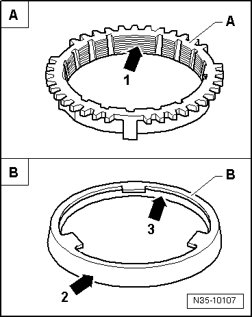
- Check the grooves -arrow 1- of synchronizer ring -A- or of the inner ring for flat spots (grooves are worn).
- On coated synchronizer rings, the coating must not be damaged.
- If an intermediate ring -B- is installed, check this intermediate ring on the outer friction surface -arrow 2- and inner friction surface -arrow 3- for "scoring", "running-in marks" and "blue discoloration (from overheating)".
- Check the cone of the gear wheel for "scoring" and "running-in marks".
- Install synchronizer wetted with transmission oil.
Gear wheels, synchronizer hubs
- Clean before pressing on and heat to max. 100 ºC with induction heater -VAS 6414-.
- Observe installation position.
Shift gears
- After installation, check shift gears for low axial play and smooth operation.
Clutch
- Do not tilt the clutch pressure plate. Loosen and tighten in a criss-cross pattern in small steps.
- To reduce the odor from a burnt clutch, thoroughly clean the clutch housing and the contact surface of the flywheel with a lint-free cloth.
Technical Data
Transmission - engine assignment
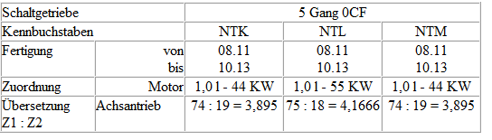
Refer to the → Electronic Parts Catalog (ETKA) for the following data:
- Individual gear ratios
- Transmission oil
- Clutch assignment

Refer to the → Electronic Parts Catalog (ETKA) for the following data.
- Individual gear ratios
- Transmission oil
- Clutch assignment

Refer to the → Electronic Parts Catalog (ETKA) for the following data:
- Individual gear ratios
- Transmission oil
- Clutch assignment
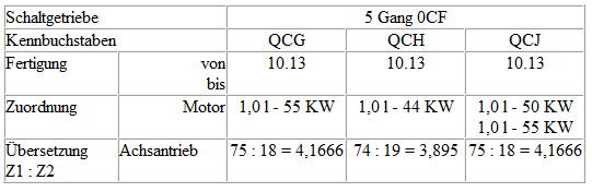
Refer to the → Electronic Parts Catalog (ETKA) for the following data:
- Individual gear ratios
- Transmission oil
- Clutch assignment
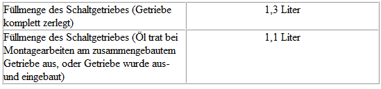
Fill quantities
Calculation of the transmission ratio
Example:

i = ZG2 : ZG1
iG = Gear ratio = ZG2 : ZG1 = 33 : 46 = 0.717
iA = Final drive ratio = ZA2 : ZA1 = 70 : 24 = 2.917
iges. = Overall ratio = iG x iA = 0.717 x 2.917 = 2.091
1) Z1 = number of teeth on driving gear, Z2 = number of teeth on driven gear
Power flow overview
Designation
Arrows point in direction of travel.

- Engine
- Clutch
- Manual transmission
- Input shaft
- Output shaft
- Differential
Ratio
Arrows point in direction of travel.
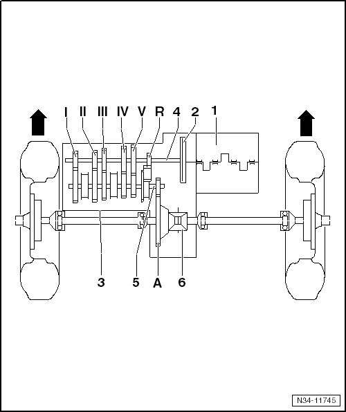
- 1st gear
- 2nd gear
- 3rd gear
- 4th gear
- 5th gear
- R - Reverse gear
- A - Final drive
Electrical components
Component location overview - electrical components
Component location overview - electrical components, manual transmission
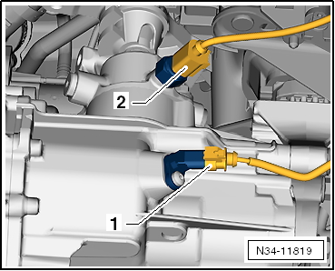
- Transmission neutral position sensor -G701-
- Location: below the shift unit
- Remove and install
- Reversing light switch -F4-
- Location: on the shift unit
- Remove and install
Component location overview - electrical components, clutch actuation, up!
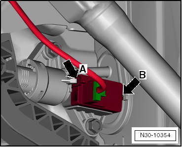
Clutch position sensor -G476-
Location: in the passenger compartment, on the clutch master cylinder.
It is held in position by the bracket -arrow A- and -arrow B-.
Remove and install clutch position sensor -G476-.
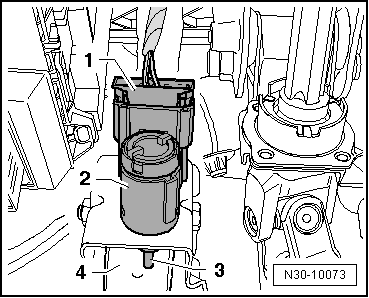
Clutch pedal switch -F36- (item -2-)
Location: in the passenger compartment, on the clutch pedal bearing bracket.
Plug connector -1- is connected; plunger -3- touches clutch pedal -4-
Remove and install clutch pedal switch -F36-.