Direct injection
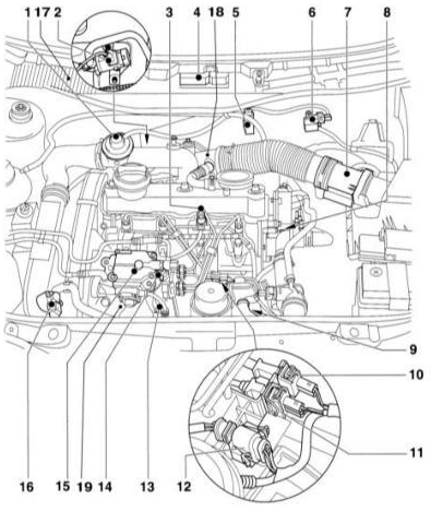 Location of fuel system components in the TDI engine compartment 1 - exhaust gas recirculation (EGR) valve 2 - intake throttle valve bypass valve 3 - injector with needle movement sensor 4 - control unit for direct fuel injection system. The altitude sensor is integrated into the control unit. 5 - EGR vacuum control solenoid valve 6 - solenoid valve for charge air pressure limitation 7 - mass air flow meter 8 - engine coolant temperature sensor 9 - engine speed sensor 10 - plug connection of needle movement sensor 11 - plug connection of engine speed sensor 12 - plug connection of high-pressure fuel pump (HPFP). For the coolant temperature sensor, quantity adjuster, control sleeve position sensor, fuel shut-off valve and start of injection valve. 13 - fuel injection start valve, oil pressure switch 14 - fuel shut-off valve 15 - fuel injection quantity control actuator of HPFP with fuel temperature sensor, quantity adjuster, control sleeve position sensor. 16 - intake air pressure sensor with intake air temperature sensor. Other components (not shown). 17 - transmission control unit 18 - PSV system heating element 19 - fuel temperature sensor, quality controller, piston modulation displacement sensor. A - brake pedal switch. B - in the footwell, at the brake pedal. B - brake light switch. B - in the footwell, at the brake pedal. C - accelerator pedal position sensor. B - in the footwell, at the brake pedal. D - clutch pedal switch. B - in the footwell, at the clutch pedal.
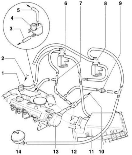 Vacuum lines of the turbocharged diesel engine (TDI) 1 - exhaust gas recirculation (EGR) valve 2 - to the vacuum box for charge air pressure control on the turbocharger 3 - to the vacuum box for intake manifold flap 4 - intake manifold flap changeover valve. The intake manifold flap reduces jerking when the engine stops. Not always fitted on AGR engines. 5 - line from tee –7– 6 - EGR control valve 7 - tee 8 - solenoid valve for charge air pressure limitation 9 - check valve 10 - from brake booster 11 - air filter 12 - check valve 13 - vacuum pump 14 - vacuum reservoir
CAUTION
The illustration shows ALH and AHF engines. AGR engines do not have a vacuum-based boost pressure control system. Explanations of how the exhaust gas recirculation system works are given in the subsection Catalytic Converter Operation. High-pressure fuel pump 1 - bolt, tightening torque: 20 Nm + 1/4 turn (90°). Always replace. 2 - HPFP drive gear 3 - nut. Do not loosen. 4 - union fitting, 25 N·m For supply line, from fuel filter. 5 - HPFP 6 - fuel shut-off valve, 40 N·m 7 - union fitting. For return line. 8 - return line. To fuel filter. 9 - nut, 25 N·m 10 - high-pressure lines, 25 N·m 11 - union fitting, 45 N·m 12 - bolt, 25 N·m 13 - injector. The third cylinder injector has a needle movement sensor. 14 - bolt, 20 N·m 15 - clamp 16 - bracket 17 - heat shield seal. Always replace. 18 - bolt, 10 N·m 19 - fuel injection start valve 20 - screen 21 - O-ring. Always replace. 22 - bolt, 25 N·m 23 - injection regulator cover 24 - bushing with nut 25 - bracket 26 - bolt, 25 N·m
Here the HPFP injects fuel directly into the combustion chamber, specifically into the recess in the piston. The HPFP generates a pressure of 900 bar and injects fuel in two stages.
Thanks to multi-hole injectors and a two-spring injector holder, a small pre-injection quantity of fuel is first delivered. Its combustion creates favorable conditions for injection of the main fuel quantity. This injection process ensures soft and quiet combustion, similar to swirl chamber combustion. The injected fuel quantity is controlled by the electronic control unit. The advantage of this injection is a reduction of fuel consumption by almost 20%. Signals from various sensors are used as control parameters of the injection process. These include:
– Accelerator pedal sensor, which informs the control unit of the accelerator pedal position. There is no throttle cable linkage to the HPFP. – Engine speed sensor. – Needle movement sensor on the injector. This sensor determines the start of injection and controls the injection process depending on engine load and speed. – Intake air pressure sensor. – Intake air temperature sensor. – Engine coolant temperature sensor. – Fuel temperature sensor. – Control sleeve position potentiometer. The control unit uses these signals as feedback for precise positioning of the control sleeve in the HPFP, which indicates the actual injected fuel quantity.
To achieve high combustion quality, the intake port is designed so that the air acquires a swirl motion on its way to the combustion chamber. Due to the better cold-start properties of the direct-injection engine, glow plug preheating is required only at temperatures below –10 °C.
Before reaching the HPFP, the fuel passes through the fuel filter. In the filter, fuel is separated from water and contaminants. Therefore, it is important to drain water from the fuel and to replace the filter element on schedule in accordance with the maintenance plan.
The HPFP requires no maintenance. Pump components are lubricated by diesel fuel. The pump is driven by the crankshaft via the toothed belt.
Warning: When working on the diesel engine fuel system, observe safety and cleanliness precautions.
Test yourself
A quick Audi A3 quiz: every answer comes with an explanation and a link to the manual page.