GENERAL INFORMATION
 Front Suspension Assembly 1 – strut mount 2 – strut 3 – wheel bearing housing 4 – wheel drive shaft joint 5 – clamp bolt 6 – control arm 7 – subframe 8 – drive shafts 9 – stabilizer bar 10 – plastic connecting link 11 – steering gear 12 – tie rod
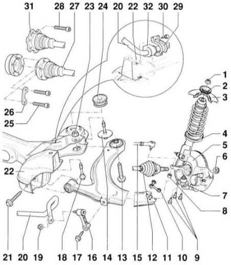 Front Suspension Components 1 – flanged nut, 60 N•m. Always replace 2 – spring seat 3 – body 4 – strut 5 – wheel bearing housing 6 – hex nut 7 – ball joint. Mark the position. When replacing the control arm, set it to the center of the oval hole and check the track (service center work). 8 – nut, 45 N•m. Self-locking, must always be replaced. 9 – bolts, 20 N•m + 90° (1/4 turn). Self-locking, must always be replaced. 10 – plate with nut 11 – control arm 12 – drive shaft 13 – combination bolt, 70 N•m + 90° (1/4 turn). Self-locking, must always be replaced. 14 – bolt, 100 N•m + 90° (1/4 turn). The thread in the body can be repaired with a Heli-Coil threaded insert. The length of the repair insert thread must equal the length of the thread in the body. 15 – tie rod 16 – connecting rod. Made of plastic. 17 – bolt, 45 N•m 18 – combination bolt, 100 N•m + 90° (1/4 turn). Self-locking, must always be replaced. The cage nut cannot be machined. If the nut is damaged, the mount must be replaced as a set. 19 – nut, 30 N•m. Self-locking, must always be replaced. 20 – stabilizer bar. To remove and install, lower the subframe. 21 – bolt, 70 N•m + 90° (1/4 turn) 22 – subframe 23 – nut. Self-locking, must always be replaced. 24 – rubber-metal mount 25 – cylindrical bolts, 40 N•m. M8 x
47. 26 – washer 27 – constant velocity joint shaft 28 – cylindrical bolts, 40 N•m. M8 x
18. 29 – stabilizer bar clamp 30 – bolt, 25 N•m 31 – Tripode joint 32 – rubber mount
The front suspension is independent. Each suspension strut includes a coil spring and a shock absorber. Both struts are bolted to the body and to the wheel bearing housings. The wheel bearing housings are controlled by triangular control arms connected to the subframe. The subframe is bolted to the underbody.
Torque from the engine is transmitted to the wheels through two drive shafts. The drive shafts are connected to the wheels and the final drive by two constant velocity joints.
Correct wheel alignment is necessary for optimal driving characteristics and minimum tire wear. If tires wear excessively or the vehicle handles poorly, have the wheel alignment checked at a service center, where optical measurement can be performed. Measuring the running gear is not possible without appropriate optical methods.
CAUTION
Welding and straightening of load-bearing and wheel-guiding components is not permitted. Self-locking nuts and bolts/nuts showing corrosion must be replaced with new ones when repairing.Test yourself
A quick Audi A3 quiz: every answer comes with an explanation and a link to the manual page.