Ignition and injection system checks
GENERAL INFORMATION
General ignition system check
Special instruments are required for systematic fault finding and repair. These instruments are normally available at a service station. Therefore, only the basic checks are described here:
PROCEDURE
1. Check the battery voltage and state of charge. Refer to the Battery Check subsection.
2. Check all fuses.
3. Disconnect and reconnect all connectors related to the engine electronic control system. Check the position of the connectors and the securing of the cables in the engine compartment.
4. Check the ground connections for security.
5. Check hoses and lines for leaks. Pay attention to damage to the hoses.
CAUTION
for hose damage. Secure any loose connections.6. Check all high-voltage leads for secure fit. Damaged insulation can cause the spark to arc to ground.
7. High-voltage leakage may occur on the inside of the distributor cap of the 1.6 L cc engine. It can be detected by thin black lines between the contacts.
8. To check whether voltage or current is supplied to the ignition system, follow the recommendations below. Note that the presence of current does not necessarily mean that the voltage is sufficient. Current supply check
A voltmeter is required for this check:
First, check the corresponding fuse (No. 32). Engines 1.6 L
9. Disconnect the connector from the ignition output stage next to the ignition coil.
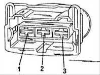
10. Connect a voltmeter between terminal 1 (positive) and terminal 3 (ground).
11. Turn the ignition on and check that the voltmeter shows a voltage close to battery voltage. If this is not the case, check the wiring up to the ignition switch. Engine 1.8 L without turbocharger
12. Remove the cover in the center of the engine and disconnect the connector from the output (final) stage.

13. Connect the voltmeter to the center terminal 4a and to ground. Turn the ignition on. The voltage should be approximately equal to battery voltage. If this is not the case, check the wiring up to the ignition switch. Engine 1.8 L with turbocharger
14. Perform the same procedure, except that the voltmeter must be connected between the terminal of the black (blue) wire and the brown (yellow) wire. The measurement results must be the same as for the standard engine without turbocharger. Checking the ignition coil(s)
Different procedures apply to different engines. Engine 1.6 L
15. First, check the external condition of the ignition coil. A burnt-out coil may sometimes have molten potting compound leaking out.
16. An ohmmeter capable of measuring high resistance is required.
17. Turn the ignition off and disconnect the wire from the connection.
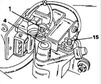
18. Measure the resistance with the ohmmeter between terminals 1 and
15. Measure the resistance of the primary winding, which should be 0.5–1.5 ohms.
19. Connect the ohmmeter between terminals 15 and
4. The measured resistance of the secondary winding should be 5–9 kOhm.
20. If the measured resistance values do not match the specified values, replace the ignition coil. The ignition coil can also be checked at a workshop. Engine 1.8 L without turbocharger
On this engine, the ignition coils and the output stage are connected to each other. Only a rough check is possible, assuming voltage is supplied (engine cover removed):
21. Disconnect all connectors from the fuel injectors.
22. Disconnect the connector from the output stage and connect a test lamp to one of the outer terminals and to ground. Crank the engine with the starter and check that the lamp flashes.
23. Perform the same check on the other terminal. The lamp should flash again.
24. If no flashing is observed, the fault may be in the following components:
– Wire connections; – Control unit; – Sensors.
25. For replacement, have the system checked at a workshop to determine the exact cause. Engine 1.8 L with turbocharger
On this engine, check the ignition coils again (the output stage is checked separately).
26. Disconnect all connectors from the fuel injectors. If the power and voltage check shows that one spark plug is not working, swap the ignition coils. If the spark appears at the other spark plug, the coil is faulty. To be fully certain, connect the spark plug to the other coil, since the spark plug may also be damaged.
27. If there is still no result, disconnect the connector of the corresponding cylinder and measure the voltage between the terminals. To do this, connect the voltmeter between both outer terminals of the connector and turn the ignition on. The voltmeter should show battery voltage. If this is not the case, there is an open circuit in the power supply to the connector.
28. Connect the test lamp to terminals 2 and 3 of the connector, then turn the ignition and starter on. If the lamp does not flash, have the entire system checked at a workshop. Checking the ignition control module
On engines 1.8 L without turbocharger, the control module has already been checked together with the ignition coils. On other engines, it is checked separately. Engine 1.6 L
The control module is located next to the ignition coil. To check it, do the following:
29. Disconnect the connector from the output stage and connect the voltmeter between terminals 2 and 3.
30. Crank the engine with the starter and check that the voltmeter shows a voltage of at least 2 V.
31. If this is not the case, replace the ignition coil and output stage together, after checking them at a workshop. Engine 1.8 L with turbocharger
The ignition control module is connected by two connectors, which are checked differently. One connector has 5 terminals and the other has 4 terminals. They are located on the left and right sides of the control module.
32. Disconnect the connectors from all fuel injectors.
33. Disconnect the 4-pin connector from the output stage (under the air filter housing cover). The connector terminals are numbered in order from left to right. Connect one wire of the LED probe to ground.
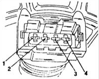
34. Connect the other probe wire in sequence to terminals 1, 2, 3 and 4 of the connector while cranking the engine with the starter. The LED should flash during all checks. If it does not, there is a fault. Reconnect the connector.
35. Disconnect the 5-pin connector. The connector terminals are numbered in order from left to right.

36. Connect the free wire of the LED probe in sequence to terminals 1, 2, 4 and 5 while cranking the engine with the starter (terminal 3 in the connector acts as ground). The LED should flash during these four checks. This means the input signal is reaching the control module.
37. If the described check gives a negative result, replace the control module. Checking the Hall sensor
As previously noted, on engines 1.8 L the Hall sensor is located on the front side of the cylinder head, directly above the timing belt. During normal operation, the engine control system uses the Hall sensor signal to determine the ignition timing for cylinder 1. If the signal is not received, the engine cannot operate for long with knock control. In this case the knock control system does not work, and ignition timing is retarded slightly to prevent knock. To check the Hall sensor, proceed as follows:
38. Disconnect the fuel injector connectors.
39. After removing the timing belt cover, the Hall sensor can be seen. The connector is located at the bottom. Pull the rubber sleeve on the Hall sensor connector back (the connector remains attached to the sensor).
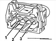
40. Connect the LED voltage probe to contacts 1 and 2 on the rear side. The contacts are marked with numbers on the back of the connector for this purpose. Crank the engine with the starter for several seconds. The LED should flash briefly every second engine revolution.
41. Disconnect the connector from the Hall sensor and turn the ignition on.
42. Connect the voltmeter between terminals 1 and 3 of the connector. The voltage should be 4.5 – 5.5 V.
43. Now connect the voltmeter between terminals 2 and 3 of the connector. The voltage should be 4.3 – 5.2 V.
44. If the voltage values match the specifications but the LED flashes, replace the Hall sensor. If the measured voltage values do not match the specifications, there is a fault in the wiring connections. Have it repaired at a workshop. Checking the engine speed sensor
The engine speed sensor is located above the flywheel ring gear. An ohmmeter is required to check it.
45. Disconnect the connector from the engine speed sensor (grey connector).
46. On the inside of the connector, connect the ohmmeter to contacts 1 and 2 (No. 1 – left). The resistance should be 480–1000 Ω. If the measured resistance is outside these limits, replace the sensor.
47. If the resistance is within specification, connect the ohmmeter between contacts 1 and 3 and between contacts 2 and
3. The ohmmeter should show infinity; otherwise, replace the sensor.
48. If all components are serviceable, there may be an open circuit in the wiring.
Checking the Knock Sensor
Only one knock sensor is installed on the 1.6 L engine. Electrical testing of this sensor is not possible. Faults can be determined by reading the fault memory of the diagnostic tester using special equipment. The connectors are located behind the coolant expansion tank and can be checked for corrosion or damaged contacts.
Test yourself
A quick Audi A3 quiz: every answer comes with an explanation and a link to the manual page.