Removal and Installation of Drive Shafts
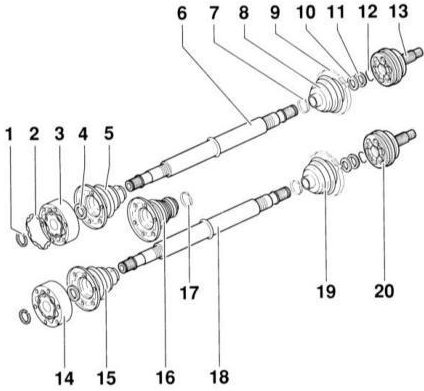 Drive shaft with constant velocity joint 1 – snap ring. Always replace. 2 – sealing gasket. Always replace. Remove the protective film and stick it to the joint. 3 – inner constant velocity joint, D 100 mm 4 – disc spring. Has teeth on the inner diameter. Large diameter contacts the joint. 5 – protective boot. For constant velocity joint D 100 mm. Lubricate the inside of the cover with AUDI «D3» sealant. 6 – shaft. For constant velocity joint D 100 mm. 7 – clamp. Always replace. 8 – protective boot. For constant velocity joint D 90 mm. 9 – clamp 10 – disc spring. Large diameter (concave side) contacts the thrust ring. 11 – thrust ring 12 – snap ring 13 – outer joint, D 90 mm. 14 – inner joint, D 94 mm. 15 – protective boot. For joint D 94 mm. 16 – protective boot. For joint D 94 mm and 100 mm, left side only (except TDI). 17 – clamp 18 – shaft. Only for joint D 94 mm. 19 – protective boot. For joint D 81 mm. 20 – outer joint, D 81 mm. Removal: use a light metal hammer to strike sharply.
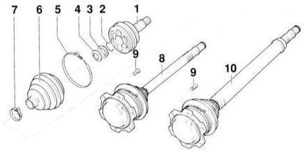 Drive shaft with tripod joint. Vehicles with AT 1 – outer joint. Replace only as a complete set. For installation, use a plastic hammer. Press on until the snap ring engages. 2 – snap ring. Insert into the shaft groove. 3 – spacer ring (plastic) 4 – disc spring. Large diameter (concave side) contacts the thrust ring. 5 – clamp. Always replace. 6 – protective boot. For joint D 90 mm. Before installation, lift the small clamp of the protective boot and fill the boot with air. 7 – clamp 8 – left shaft. With internal Tripode joint. If damaged, the inner joint and shaft must be replaced. 9 – internal Torx bolt, 45 N·m 10 – right shaft. With Tripode joint. If damaged, the inner joint and shaft must be replaced.
CAUTION
After unscrewing the twelve-point nut (axle nut) that secures the drive shaft to the hub, do not set the vehicle with full load on its wheels and do not move it. Without axial preload, the wheel bearing may be damaged. If necessary, install the outer joint in place of the drive shaft and tighten it to 50 N·m.REMOVAL
PROCEDURE
1. Remove the wheel trim cover. On alloy wheels, remove the caps using the removal hooks from the onboard tool kit.
2. Loosen the twelve-point wheel hub nut on the drive shaft without unscrewing it.
CAUTION
When unscrewing the drive shaft retaining nut, the vehicle should, if possible, stand with its wheels on the ground. If the vehicle is raised, position the wrench so that the unscrewing force acts vertically downward. Otherwise, the vehicle may slide sideways off the supports. High unscrewing torque. Risk of injury!3. Mark the position of the corresponding front wheel relative to the hub with paint. This allows the balanced wheel to be installed in its original position during assembly. Loosen the wheel bolts with the vehicle on the ground. Raise the front of the vehicle, place it on stands and remove the front wheel.
CAUTION
Raising and placing the vehicle on stands is hazardous. Therefore, before performing this operation, read the subsection Jacking Up the Vehicle.
4. Mark the position of the bolts -1- of the ball joint with a felt-tip pen or scribe around them. Otherwise, the front suspension will need to be measured and adjusted during later installation. Unscrew the bolts -1-.
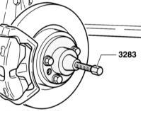
5. If the drive shaft cannot be removed from the hub by hand, remove the shaft using a puller. Audi service workshops use puller AUDI-3283 for this.
CAUTION
Do not let the shaft hang, otherwise the inner joint may be damaged by bending.6. Unscrew the internal Torx bolts of the drive shaft on the transmission flange. An insert for internal Torx, for example, HAZET 990 Lg-, is required for this.
8.
7. Vehicles with manual transmission: Tilt the strut outward and remove the drive shaft from the wheel bearing housing. Vehicles with automatic transmission:
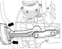
8. Unscrew the mounting bolts (arrows in the illustration) of the AT support to the unit carrier.

9. Insert a pry bar between the carrier beam and the cylinder block and move the block in the direction of travel. The tripod joint of the drive shaft can be removed at the same time. INSTALLATION
10. Clean the splines and thread of the drive shaft and the hub of rust and other contamination with a wire brush.
11. Secure the shaft to the transmission. Tighten the socket head bolts diagonally. Tightening torque, MT (constant velocity joint): 40 N·m; AT (tripod joint): 45 N·m.
12. Lubricate the contact surface of the hexagon nut and the splines of the outer joint with clean engine oil. Insert the outer joint into the hub splines as far as possible.
13. Secure the ball joint to the control arm. Install the mounting bolts in the oval holes so that the previously applied marks align. Tighten the bolts to 20 N·m, then turn them an additional 90° (1/4 turn) with a rigid wrench.
CAUTION
When installing into a new control arm, set the mounting bolts to the middle position and tighten. Finally, measure the camber, refer to the subsection Wheel Alignment Angles.14. Install the inner joint of the drive shaft and tighten the socket head bolts.
Tightening torques:
M8 40 N·m M10 80 N·m
15. Vehicles with AT: Tighten the transmission mount bolts to the carrier beam to 25 N·m.
16. Push the outer joint in until it stops against the wheel bearing.
17. Tighten the hexagon nut to 300 N·m, then loosen it by 1/2 turn.
18. Tighten the hexagon nut to 50 N·m, then turn it an additional 45° (1/4 turn) with a rigid wrench.
CAUTION
For tightening through a specified angle, the HAZET angle washer is required.6690. If this washer is not available, the hexagon nut can be tightened as follows.
19. Lower the vehicle so that the wheels contact the ground.
20. Tighten the hexagon nut to 300 N·m, then loosen it again by 1/2 turn.
21. Tighten the hexagon nut to 50 N·m.
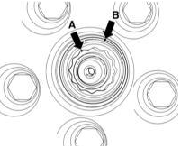
22. Mark one flat of the nut (arrow A in the illustration). Make the second mark (arrow B) on the hub edge across from the next flat. Note: The distance from one flat to the next is 45°.
23. Turn the hexagon nut with a wrench until both marks align.
Test yourself
A quick Audi A3 quiz: every answer comes with an explanation and a link to the manual page.