Clutch - GENERAL INFORMATION
Specifications
CAUTION
Individual specifications are also given in the text of the chapter, and where their observance is mandatory they are printed in boldGeneral Specifications Clutch Type: Single-plate dry clutch with hydraulic actuation. Maximum disc runout: 0.5 mm. Drive Shafts Length, MT (02A) and AT (096): Left drive shaft 447.4 mm; Right drive shaft 681.5 mm. MT (020): Left drive shaft 455.5 mm; Right drive shaft 691.5 mm. Balance weight position (measured from joint surface to weight surface): 524.0 - 526.0 mm. Joint Lubrication Grease type: AUDI G 000 603. Outer joint, ball and tripod type. Joint Ø 81 mm: Total 80 g; Volume in joint 40 g; Volume in protective boot 40 g. Joint Ø 90 mm: Total 120 g; Volume in joint 80 g; Volume in protective boot 40 g. Inner joint, ball type: Joint Ø 94 mm: Total 90 g; Volume in joint 40 g; Volume in protective boot 50 g. Joint Ø 100 mm: Total 120 g; Volume in joint 50 g; Volume in protective boot 70 g. Inner joint, tripod type: Total 180 g; Volume at front of joint 90 g; Volume at rear of joint 90 g. When replacing the protective boot, add grease to the joint as necessary. Tightening Torques Tightening torques for fasteners are also given in the text of the chapter and in some illustrations*.
*Tightening torques shown in bold in the text must be observed exactly. Torques not shown in bold are approximate only. Clutch Clutch to flywheel: 20 Nm. Clutch slave cylinder bolt: 25 Nm. Clutch master cylinder to pedal bracket: 25 Nm. Drive Shafts Hub nut: 265 Nm. With "plus" suspension: 200 Nm, loosen by 1 turn, then tighten to 50 Nm + 30°. Drive shaft to transmission flange: M8 40 Nm; M10 80 Nm.
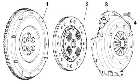 Clutch disc and pressure plate. Engine 1.8 L 1 – Flywheel. The friction surface must not have grease grooves. Make sure the centering pins are securely seated. 2 – Clutch disc. Observe installation position: the spring retainer faces the pressure plate. 3 – Pressure plate. 4 – Twelve-point bolt, 20 Nm. Loosen and tighten evenly in a crisscross pattern.
CAUTION
: For versions with a dual-mass flywheel, Allen (internal hex) bolts are fitted, tightening torque 13 N·mCAUTION
Clean the splines of the transmission input shaft and the driven disc if the old disc is reused, and the hub splines. Remove rust. Apply a thin layer of MoS grease to the splines.2. Always remove excess grease.
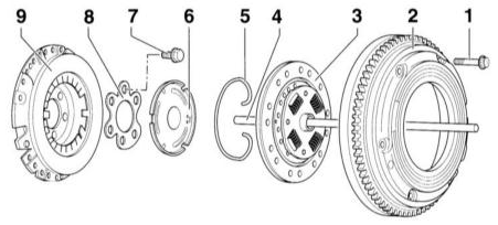 Clutch disc and pressure plate. Engines 1.6 L 1 – Twelve-point bolt, 20 Nm. Loosen and tighten evenly in a crisscross pattern. 2 – Flywheel. The friction surface must not have grease grooves.
CAUTION
: The installation depth of the TDC sensor must match the different flywheel sizes. Therefore, two different color-coded threaded plugs are screwed into the clutch housing. 3 – clutch driven disc. Apply a thin layer of MoS grease to the centering elements and splines.2. 4 – Release rod. Lubricate in the area of the guide bushing in the transmission input shaft. 5 – Retaining ring. 6 – Release plate. Apply a thin layer of MoS2 grease (VW G 000 100) to the contact surface with the rod. 7 – Mounting bolt. Tightening torque: 60 Nm + 1/4 turn (90°). Always replace bolts. 8 – Intermediate plate. 9 – Clutch disc. Maximum runout: 0.2 mm. Replace the disc if rivets are damaged or loose.
 Clutch hydraulic actuation 1 – Brake fluid reservoir. 2 – Compensating hose. 3 – Clutch master cylinder. 4 – Clip. 5 – Clutch pedal. 6 – Nut, 25 Nm. Self-locking, always replace. 7 – Bracket. 8 – Hydraulic line. 9 – Support. 10 – Dust boot. 11 – Bleed nipple. 12 – Clutch slave cylinder. 13 – Flanged bolt, 25 Nm. 14 – Manual transmission. 15 – Retaining clip. 16 – Clip. 17 – Hydraulic line. 18 – Line connection/plug-in connector. 19 – O-ring. Push onto the line connection after moistening with brake fluid. 20 – Retaining clip.
When a gear is engaged, the clutch disconnects the power link between the engine and the transmission. Through friction engagement, it allows smooth transmission of torque to the drivetrain when starting from a standstill.
The clutch consists of a pressure plate, a clutch disc, a release bearing, and a hydraulic actuation system.
The pressure plate is bolted to the flywheel. The flywheel is in turn connected to the engine crankshaft. The clutch disc is located between the pressure plate and the flywheel and is pressed against the flywheel by the pressure plate. The clutch disc is connected to the transmission input shaft by a splined connection.
When the clutch pedal is depressed, pressurized fluid is transferred from the master cylinder, located at the lower part of the vehicle, to the slave cylinder. The slave cylinder piston presses on the release bearing, which acts on the pressure plate. As a result, the clutch disc moves away from the flywheel and the power link between the engine and the transmission is interrupted. The clutch hydraulic system uses brake fluid from the reservoir.
Each time the clutch is engaged and disengaged, the friction linings of the clutch disc wear due to the applied force. The clutch disc is a wear part. However, its average service life exceeds 100,000 km. Wear depends mainly on load (towing a trailer) and driving style. The clutch is maintenance-free because it is self-adjusting.
Engines are generally equipped with a dual-mass flywheel. The dual-mass flywheel has a spring-damper system that helps reduce engine vibrations. It also reduces noise at low engine speeds. In this case, the clutch disc consists of a hub, a driven plate, and friction linings. There are no torsion springs.
Test yourself
A quick Audi A3 quiz: every answer comes with an explanation and a link to the manual page.