Diesel Engine Glow Plug System
General Description
At low engine temperature, the fuel cannot self-ignite due to the compression ratio alone. Therefore, additional fuel heating is required.
For this purpose, a glow plug is screwed into each combustion chamber. The glow plug consists of a body with a heating element pressed into it. When voltage is applied to the glow plug, the heating element heats up to a temperature above 850°C within a few seconds, which prepares the engine for starting within no more than 5 s. After the glow indicator lamp on the instrument panel goes out, the engine is ready to start.
The duration of the heating process and the additional automatic heating after engine start (up to 20 s) are controlled by the DDE control unit through the glow plug relay. The glow plug circuit diagram is provided at the end of this Manual.
Glow Plug Inspection, Removal and Installation
If the engine is difficult to start, first check the compression in the cylinders. If compression is insufficient, the engine will not start at low temperature. Refer to the Compression Check section.
* The DDE control unit is equipped with a fault memory that records faults occurring in the electrical part of the diesel fuel system. At a service station, the data stored in memory can be read using special equipment.
INSPECTION
1. Remove the engine covers and the charge air pipe above the glow plugs.
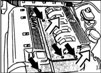
2. The glow plugs are located under the intake passages.
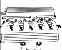
3. Disconnect the glow plug cable (arrow in the accompanying illustration).

4. Connect the voltage tester to the positive terminal (+) and then to each glow plug in turn.
5. If the LED lights: The glow plug is serviceable. For a more precise check, measure the current with an ammeter.
6. If the LED does not light: The glow plug is faulty. Replace it.
REMOVAL
1. Remove the intake manifold. Refer to the Intake Manifold Removal and Installation section.
2. Disconnect cables (1) and (2). Unscrew the glow plugs and inspect them visually. Refer to the accompanying illustration.

INSTALLATION
1. Apply high-temperature copper paste "CRC" to the glow plug threads. Screw in the glow plugs. Tighten to a torque of 25 N·m.
* Do not exceed the specified tightening torque, as the annular clearance between the heating element and the threaded part of the plug may increase.
2. Connect the cable to the glow plugs. Tighten the retaining nut to a torque of 5 N·m.
3. Secure the intake manifold to the cylinder head to a torque of 25 N·m. Replace all seals with new ones. Secure the oil filter housing brackets and the recirculation system pipe to the intake manifold also to a torque of 25 N·m.
4. Install the engine covers and the charge air pipe.
Glow Plugs with Burnt-Out Heating Elements
4. Connect the voltage tester to the positive terminal (+) and then to each glow plug in turn.
5. If the LED lights: The glow plug is serviceable. For a more precise check, measure the current with an ammeter.
6. If the LED does not light: The glow plug is faulty. Replace it.
REMOVAL
1. Remove the intake manifold. Refer to the Intake Manifold Removal and Installation section.
2. Disconnect cables (1) and (2). Unscrew the glow plugs and inspect them visually. Refer to the accompanying illustration.
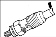
Burnt-out glow plug heating elements are often the result of faulty injector operation.
If damaged glow plugs are found (arrow), replace them and be sure to check the operation of the injectors.
Glow Plug Relay Inspection, Removal and Installation
PROCEDURE
1. Remove the clean air filter box in the engine compartment, at the rear right. This provides access to the fuse box and relays.
2. Remove the fuse box cover by unscrewing the retaining bolts.
3. Disconnect the glow plug relay (1). 2 - DDE control unit. Refer to the accompanying illustration.
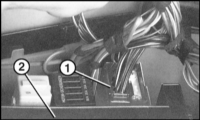
4. Check the 80 A fuse next to the connector plug. If it has failed, replace it. First determine the cause of the overload. Refer to the accompanying illustration.
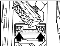
5. Disconnect the thick positive wire from the relay housing.
The illustration shows the glow plug relay connection diagram. A similar diagram is located on the relay cover.
G1...G6: glow plugs 1...6;
Kl. 15: positive, switched through the ignition switch;
Kl. 30: battery positive;
Ust: control voltage (from the DME control unit);
Dia: diagnostic connection

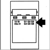
6. Connect the battery and the voltage tester to the terminal 15 plug and to ground. Turn the ignition on. The tester LED should light. If not, check the voltage supply from the ignition switch.
7. If the LED lights, check the wire to the glow plugs. Replace it if necessary. If this does not solve the problem, replace the glow plug relay.
8. Install the control unit cover.
9. Close the box. Install the cabin air filter.
Test yourself
A quick BMW 1 quiz: every answer comes with an explanation and a link to the manual page.