Front Suspension Crossmember Removal and Installation
* After installing the crossmember, the front suspension geometry must be checked.
REMOVAL
1. Attach a lifting device to the engine and loosen the mount bolts, refer to Oil Pan Removal and Installation.
2. Mark the position of the front wheels relative to the hub with paint. This ensures the balanced wheel returns to its original position. Loosen the wheel bolts with the vehicle on the ground. Raise and support the vehicle on stands. Remove the front wheels.
3. Disconnect the links from the suspension crossmember. Remove the caps first.
4. Disconnect the control arms from the crossmember.
5. Remove the heat shield and the engine shield bracket.
6. Place a support under the strut from the outside.
7. Measure the thread-in length (A) of both tie rods, mark or count the number of turns when unscrewing, and record the value.
8. Loosen the lock nut (arrow in the illustration) and unscrew the tie rods.
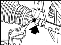
9. Remove the mounting bolts and remove the steering gear from the crossmember.
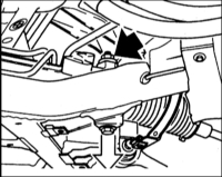
10. Remove the mounting bolts and detach the stabilizer bar from the suspension crossmember.
11. Place a garage jack under the suspension crossmember.
12. Remove three mounting bolts on the left and right sides of the crossmember and lower it. To do this, partially remove the trim near the rear bolts.
* The mounting bolts are of different lengths. Record their lengths.
INSTALLATION
1. Install the front suspension crossmember and secure it to the engine crossmember with bolts. Torque to 75 N·m. Insert both short bolts at the rear.
2. Secure the stabilizer bar to the suspension crossmember with bolts. Torque to 20 N·m.
3. Secure the steering gear to the crossmember with new self-locking nuts. Torque to 40 N·m.
4. Screw in the steering tie rods to the previously measured dimension (A), refer to Illustration 7.8. Secure the tie rods with lock nuts. Torque to 45 N·m.
5. Install the heat shield and the engine shield bracket.
6. Secure the lower control arm and link to the front suspension crossmember with new self-locking nuts. Do not tighten the nuts fully.
7. Secure the engine mounts, refer to Engine Removal and Installation.
8. Remove the lifting device from the engine.
9. Install the front wheels. Do not lubricate the wheel bolts with oil. Install the wheels so that the previously made marks align. Lower the vehicle onto the wheels. Tighten the wheel bolts in a crisscross sequence. Torque to 100 N·m.
10. Set the vehicle to its normal position. The following conditions must be met:
a) The vehicle must be standing on its wheels.
b) The front seats must be in the middle position.
c) Each seat must carry a load of 68 kg.
d) A load of 68 kg must be placed in the center of the rear seat.
e) A load of 21 kg must be placed in the center of the luggage compartment.
f) The fuel tank must be completely filled.
11. Secure the link to the front crossmember with new self-locking nuts, torque to the value given in the Specifications. Install the caps.
12. Secure the lower control arm to the front crossmember, torque to the values given in the Specifications.
Test yourself
A quick BMW 1 quiz: every answer comes with an explanation and a link to the manual page.