Powertrain

Diagnosis and Testing - Engine Cooling

11steps
~76min
5/5difficulty
2special tools
Done 0 of 11

Special Service Tools)
Coolant/Battery Refractometer
ROB75240 or equivalent
D-Gas Adapter
300-OTC014-R1068 or equivalent
Radiator Tester
014-R1072 or equivalent
UView® Combustion Tester
UVU560000-R

Diagnostic Trouble Code (DTC) Chart

The diagnosis in this manual assumes a certain level of skill and knowledge of Ford-approved diagnostic procedures.
REFER TO: Diagnostic Methods (100-00 General Information, Description and Operation).


Module Trouble Code Description Action
PCM P0125:00 Insufficient Engine Coolant Temperature for Closed Loop Fuel Control GO to Pinpoint Test C
PCM P0128:00 Thermostat Engine Coolant Temperature Below Thermostat Regulating Temperature GO to Pinpoint Test C
PCM P01E4:00 Engine Coolant Temperature Sensor 3 Circuit Range/Performance GO to Pinpoint Test F
PCM P01E5:00 Engine Coolant Temperature Sensor 3 Circuit Low Signal GO to Pinpoint Test F
PCM P01E6:00 Engine Coolant Temperature Sensor 3 Circuit High Signal GO to Pinpoint Test F
PCM P0217:00 Engine Coolant Overtemperature Condition GO to Pinpoint Test B
PCM P1299:00 Cylinder Head Overtemperature Protection Active GO to Pinpoint Test B
PCM P237C:00 Exhaust Heat Exchanger Exhaust Bypass Valve 'A' Control Circuit/Open GO to Pinpoint Test D
PCM P237D:00 Exhaust Heat Exchanger Exhaust Bypass Valve 'A' Control Circuit Low GO to Pinpoint Test D
PCM P237E:00 Exhaust Heat Exchanger Exhaust Bypass Valve 'A' Control Circuit High GO to Pinpoint Test D
PCM P237F:00 Exhaust Heat Exchanger Exhaust Bypass Valve 'A' Control Performance GO to Pinpoint Test D
PCM P26CA:00 Engine Coolant Pump Control Circuit/Open GO to Pinpoint Test E
PCM P26CB:00 Engine Coolant Pump Performance/Stuck Off GO to Pinpoint Test E
PCM P26CE:00 Engine Coolant Pump Overspeed/Air in System GO to Pinpoint Test A
PCM P26D0:00 Engine Coolant Pump Control Module System Voltage Low GO to Pinpoint Test E
PCM P26D1:00 Engine Coolant Pump Control Module System Voltage High GO to Pinpoint Test E
PCM P26D2:00 Engine Coolant Pump Control Module Overtemperature GO to Pinpoint Test B
PCM P26D3:00 Engine Coolant Pump Power Supply Voltage Circuit GO to Pinpoint Test E
PCM P2AFD:00 Engine Coolant Temperature Sensor 4 Circuit Range/Performance GO to Pinpoint Test G
PCM P2AFE:00 Engine Coolant Temperature Sensor 4 Circuit Low Signal GO to Pinpoint Test G
PCM P2AFF:00 Engine Coolant Temperature Sensor 4 Circuit High Signal GO to Pinpoint Test G
PCM P2C22:00 Exhaust Heat Exchanger Exhaust Bypass Valve 'A' Position Sensor Circuit GO to Pinpoint Test D
PCM P2C23:00 Exhaust Heat Exchanger Exhaust Bypass Valve 'A' Position Sensor Performance GO to Pinpoint Test D
PCM U019F:00 Lost Communication with Engine Coolant Pump Control Module GO to Pinpoint Test E

Global Customer Symptom Codes (GCSC) Table

The diagnosis in this manual assumes a certain level of skill and knowledge of Ford-approved diagnostic procedures.
REFER TO: Diagnostic Methods (100-00 General Information, Description and Operation).


Symptom Action

Symptom Chart

The diagnosis in this manual assumes a certain level of skill and knowledge of Ford-approved diagnostic procedures.
REFER TO: Diagnostic Methods (100-00 General Information, Description and Operation).

Condition Action
Coolant Loss GO to Pinpoint Test A
Engine Overheats. GO to Pinpoint Test B
Engine Does Not Reach Normal Operating Temperature. GO to Pinpoint Test C
Block Heater Inoperative (if equipped)
  • CHECK the continuity of all 3 power cable circuits. If the resistance of any circuit exceeds 5 Ohms, INSTALL a new power cable.
  • CHECK the resistance of the block heater. If the resistance is not between 30 and 40 Ohms, INSTALL a new block heater.
    Refer to: Block Heater (303-03C Engine Cooling, Removal and Installation).
Electric Cooling Fan Inoperative at one or more speeds or operates incorrectly.
Refer to: Cooling Fan Control (303-03C Engine Cooling, Diagnosis and Testing).
Electric Cooling Fan Runs Continuously.
Refer to: Cooling Fan Control (303-03C Engine Cooling, Diagnosis and Testing).
Auxiliary Coolant Pump Malfunction GO to Pinpoint Test E

Pinpoint Tests


PINPOINT TEST A: COOLANT LOSS

Normal Operation and Fault Symptoms

The engine cooling system is a closed system. It allows for expansion and contraction of the coolant, and changes in pressure, as the coolant heats and cools during engine operation. Various gaskets, seals, hoses and clamps retain the coolant within the cooling system and prevent other fluids and contaminants from entering the cooling system.

DTC Fault Trigger Conditions

Trouble Code Description Fault Trigger Condition
PCM P26CE:00 Engine Coolant Pump Overspeed/Air in System Set in the PCM when engine speed is exceeded.

Possible Sources

  • Coolant Hoses or Tubes
  • Clamps
  • Thermostat O-Ring or Gasket
  • Coolant Pump O-Ring or Gasket
  • Thermostat Housing
  • Oil Cooler (internal or external leakage possible) (if equipped)
  • Transmission Fluid Warmer (internal or external leakage possible)
  • Transmission Fluid Warmer Control Valve
  • Radiator
  • Pressure Relief Cap
  • Coolant Pump Weep Hole Leaking
  • Cabin Heater Coolant Pump (if equipped)
  • Heater Core
  • Lower Intake Manifold
  • Engine Gaskets (internal or external leakage possible)
  • Degas bottle
  • Engine Block Core Plugs
  • Cylinder Head Core Plugs
  • Engine Block Heater (if equipped)
A1 INSPECT AND VERIFY
  • Inspect and verify.

Is there a concern?
Yes REPAIR as necessary.
No GO to A2
A2 CHECK THE ENGINE COOLANT LEVEL AND PRESSURE TEST THE ENGINE COOLING SYSTEM
  • Ignition OFF.
  • Visually check the engine coolant level in the degas bottle and adjust if necessary. Pressure test the engine cooling system. Refer to Component Tests, Cooling System Pressure Test in this section.

Is there an external leak in the engine cooling system?
Yes REPAIR or INSTALL new components.
No GO to A3
A3 CHECK THE ENGINE COOLANT FOR INTERNAL LEAKAGE
  • Inspect the engine coolant in the degas bottle for signs of engine oil.

Is engine oil visible in the engine coolant?
Yes
REFER TO: Engine (303-00 Engine System - General Information, Diagnosis and Testing).
No GO to A4
A4 CHECK THE ENGINE OIL FOR COOLANT CONTAMINATION
  • Remove the engine oil dipstick.

Is engine coolant visible in the engine oil?
Yes
REFER TO: Engine (303-00 Engine System - General Information, Diagnosis and Testing).
No GO to A5
A5 CHECK THE ENGINE COOLANT FOR TRANSMISSION FLUID CONTAMINATION
  • Check the engine coolant in the degas bottle for signs of transmission fluid.

Is transmission fluid visible in the engine coolant?
Yes INSTALL a new transmission fluid warmer.
REFER TO: Transmission Fluid Cooler (307-02B Transmission Cooling - Automatic Transmission - HF45, Removal and Installation).
REPAIR the transmission as necessary. REFER TO: DTC Chart and Location Tests - 1.5 L EcoBoost (132 kW/180 L HP) - I3 (Y1) (307-01A Automatic Transmission - 8-Speed Automatic Transmission - 8F35/8F40, Diagnosis and Testing).
CHECK the system for normal operation.
No GO to A6
A6 CHECK THE TRANSMISSION FLUID FOR ENGINE COOLANT CONTAMINATION
  • Remove the transmission fluid level plug.
  • Check the transmission fluid for engine coolant contamination.

Is engine coolant visible in the transmission fluid?
Yes INSTALL a new transmission fluid warmer.
REFER TO: Transmission Fluid Cooler (307-02B Transmission Cooling - Automatic Transmission - HF45, Removal and Installation).
REPAIR the transmission as necessary. REFER TO: DTC Chart and Location Tests - 1.5 L EcoBoost (132 kW/180 L HP) - I3 (Y1) (307-01A Automatic Transmission - 8-Speed Automatic Transmission - 8F35/8F40, Diagnosis and Testing).
CHECK the system for normal operation.
No GO to A7
A7 CHECK THE COOLING SYSTEM FOR COMBUSTION GASES
  • Using the Cooling System Combustion Gas Tester, follow the instructions supplied with the tester, check the engine coolant for combustion gases.

Are combustion gases present?
Yes
REFER TO: Engine (303-00 Engine System - General Information, Diagnosis and Testing).
No Replace the engine coolant pump if DTC P26CE is present.
REFER TO: Engine Coolant Pump (303-03C Engine Cooling, Removal and Installation).
PINPOINT TEST B: ENGINE OVERHEATS

Normal Operation and Fault Symptoms

The engine cooling system maintains engine temperature during operation. Correct coolant flow through the engine, radiator and the remainder of the cooling system passages and components is important to maintain correct engine temperature.

DTC Fault Trigger Conditions

Trouble Code Description Fault Trigger Condition
PCM P26D2:00 Engine Coolant Pump Control Module Overtemperature Set in the PCM when the CHT sensor detects an engine overheat condition.
PCM P1299:00 Cylinder Head Overtemperature Protection Active Set in the PCM when the CHT sensor detects an engine overheat condition.
PCM P0217:00 Engine Coolant Overtemperature Condition Set in the PCM when the CHT sensor detects an engine overheat condition.

Possible Sources

  • Low coolant level
  • Engine coolant external leakage
  • Air trapped in the system
  • Pressure relief cap installation
  • Restricted airflow through the A/C condenser/radiator
  • Engine coolant internal leakage
  • Coolant condition/concentration
  • Non-OEM engine enhancement components
  • Electric cooling fan
  • TP Sensor
  • Radiator
  • Thermostat
  • Coolant Pump
  • Restricted coolant flow
  • Active grille shutter assembly
B1 INSPECTION AND VERIFICATION
  • Complete the inspection and verification procedure described in this section.

Is there a concern?
Yes REPAIR as necessary.
No GO to B2
B2 CHECK THE PCM (POWERTRAIN CONTROL MODULE) FOR DTCS
  • The ignition is on.
  • Using a scan tool, perform the PCM self-test.

Is DTC P0217 and/or P1299 present?
Yes GO to B4
No Actual engine overheating is not confirmed. CHECK the operation of the engine coolant temperature gauge.
REFER TO: Instrument Cluster, Message Center and Warning Chimes (413-01 Instrument Cluster, Message Center and Warning Chimes, Diagnosis and Testing).
If any other PCM DTCs are present,
REFER TO: Engine Control Systems (303-14C Electronic Engine Controls, Diagnosis and Testing).
B3 CHECK FOR ACTIVE GRILLE SHUTTER DTCS
  • Review the PCM DTCs.

Are any active grille shutter DTCs present?
Yes
REFER TO: Active Grille Shutter (501-02 Front End Body Panels, Diagnosis and Testing).
No GO to B4
B4 CHECK FOR AIRFLOW OBSTRUCTION AND MISSING AIR DEFLECTORS
  • Check the radiator or A/C condenser for external obstructions such as leaves or cardboard, and check that all air deflectors are installed.

Is there airflow obstruction or are air deflectors missing?
Yes REPAIR as necessary.
No GO to B5
B5 CHECK THE ENGINE COOLANT LEVEL AND PRESSURE TEST THE COOLING SYSTEM
  • Ignition OFF.
  • Visually check the engine coolant level in the coolant recovery reservoir and adjust if necessary. Pressure test the cooling system.

Is there an external leak in the engine cooling system?
Yes REPAIR or INSTALL new components.
No GO to B6
B6 CHECK THE ENGINE COOLANT FOR INTERNAL LEAKAGE
  • Inspect the engine coolant in the coolant recovery reservoir for signs of engine oil.

Is engine oil visible in the coolant?
Yes
REFER TO: Engine (303-00 Engine System - General Information, Diagnosis and Testing).
No GO to B7
B7 CHECK THE ENGINE OIL FOR COOLANT CONTAMINATION
  • Remove the engine oil dipstick.

Is engine coolant visible in the engine oil?
Yes
REFER TO: Engine (303-00 Engine System - General Information, Diagnosis and Testing).
No GO to B8
B8 CHECK THE ENGINE COOLANT FOR TRANSMISSION FLUID CONTAMINATION
  • Check the engine coolant in the degas bottle for signs of transmission fluid.

Is transmission fluid visible in the engine coolant?
Yes INSTALL a new transmission fluid cooler.
REFER TO: Transmission Fluid Cooler (307-02B Transmission Cooling - Automatic Transmission - HF45, Removal and Installation).
REPAIR the transmission as necessary. REFER TO: DTC Chart and Location Tests - 1.5 L EcoBoost (132 kW/180 L HP) - I3 (Y1) (307-01A Automatic Transmission - 8-Speed Automatic Transmission - 8F35/8F40, Diagnosis and Testing).
CHECK the system for normal operation.
No GO to B9
B9 CHECK THE TRANSMISSION FLUID FOR ENGINE COOLANT CONTAMINATION
  • Remove the transmission fluid level plug.
  • Check the transmission fluid for engine coolant contamination.

Is engine coolant visible in the transmission fluid?
Yes INSTALL a new transmission fluid cooler.
REFER TO: Transmission Fluid Cooler (307-02B Transmission Cooling - Automatic Transmission - HF45, Removal and Installation).
REPAIR the transmission as necessary. REFER TO: DTC Chart and Location Tests - 1.5 L EcoBoost (132 kW/180 L HP) - I3 (Y1) (307-01A Automatic Transmission - 8-Speed Automatic Transmission - 8F35/8F40, Diagnosis and Testing).
CHECK the system for normal operation.
No GO to B10
B10 CHECK THE COOLING SYSTEM FOR COMBUSTION GASES
  • Using the Cooling System Combustion Gas Tester, follow the instructions supplied with the tester, check the engine coolant for combustion gases.

Are combustion gases present?
Yes
REFER TO: Engine (303-00 Engine System - General Information, Diagnosis and Testing).
No GO to B11
B11 CHECK THE ENGINE COOLANT CONDITION
  • Check the engine coolant for dirt, rust or contamination and check the engine coolant concentration.

Is the engine coolant condition satisfactory?
Yes GO to B12
No FLUSH the engine cooling system.
REFER TO: Engine Cooling System Flushing (303-03C Engine Cooling, General Procedures).
B12 CHECK THE ELECTRIC COOLING FAN OPERATION
  • Start the engine.
  • Set the climate control function selector to MAX A/C and the fan switch to HI.

Did the electric cooling fan operate?
Yes GO to B13
No CHECK the engine cooling electric fan operation.
REFER TO: Cooling Fan Control (303-03C Engine Cooling, Diagnosis and Testing).
B13 CHECK THE COOLANT PUMP OPERATION
  • Start the engine.
  • Run the engine for 30 minutes. Set the climate control function selector to MAX HEAT. Feel the heater outlet hose.

Is the heater outlet hose hot?
Yes GO to B14
No INSTALL a new coolant pump.
REFER TO: Coolant Pump (303-03C Engine Cooling, Removal and Installation).
B14 CHECK THE THERMOSTAT OPERATION
  • Start the engine.
  • Run the engine for 30 minutes. Set the climate control function selector to MAX HEAT. Feel the radiator lower hose.

Is the radiator lower hose hot?
Yes CHECK the temperature gauge operation.
REFER TO: Instrument Cluster, Message Center and Warning Chimes (413-01 Instrument Cluster, Message Center and Warning Chime, Diagnosis and Testing).
No GO TO B15
B15 VISUALLY CHECK THE THERMOSTAT
  • Perform a visual inspection of the thermostat in the Component Testing section of this section.

Is the thermostat damaged?
Yes INSTALL a new thermostat.
REFER TO: Thermostat Housing (303-03C Engine Cooling, Removal and Installation).
No INSTALL a new thermostat.
REFER TO: Thermostat Housing (303-03C Engine Cooling, Removal and Installation).
If the engine still overheats, INSTALL a new radiator. REFER TO: Radiator (303-03C Engine Cooling, Removal and Installation).
PINPOINT TEST C: ENGINE DOES NOT REACH NORMAL OPERATING TEMPERATURE

Normal Operation and Fault Symptoms

The engine cooling system maintains engine temperature during operation. Correct coolant flow through the engine, radiator and the remainder of the cooling system passages and components is important to maintain correct engine temperature.

Engine coolant flows mainly from the engine to the radiator circuit and back to the coolant pump. Coolant is sent from the coolant pump through the cylinder block and cylinder head. A separate circuit from the engine also supplies the heater core with coolant. The coolant pump circulates the coolant. The thermostat is a coolant temperature-actuated control valve. When the thermostat is closed, coolant flow bypasses the radiator circuit and returns to the coolant pump. When the thermostat is open, coolant flows through the radiator circuit to transfer engine heat to the outside air.

A concern that the engine does not reach normal operating temperature usually occurs when coolant flow through some coolant circuits (radiator, heater core) is greater than expected for the conditions. Heat is not allowed to build up in the engine because the heat exchanger removes too much heat, including the radiator, heater core and oil cooler. In addition, a suspected concern that the engine does not reach normal operating temperature may be related to low coolant level or air trapped in the system, which prevents hot coolant from reaching the heater core, a malfunctioning climate control system, or a concern perceived or related to an incorrect engine temperature sensor reading.

DTC Fault Trigger Conditions

Trouble Code Description Fault Trigger Condition
PCM P0125:00 Insufficient Engine Coolant Temperature for Closed Loop Fuel Control Set in the PCM when the CHT sensor does not reach the required temperature to enter closed loop operating conditions within a specified time after engine start.
PCM P0128:00 Thermostat Engine Coolant Temperature Below Thermostat Regulating Temperature Set in the PCM when the thermostat monitor does not reach the required engine operating temperature within a specified time after engine start.

Possible Sources

  • Low coolant level
  • Thermostat
  • Temperature Gauge
  • CKP
C1 PERFORM INSPECTION AND CHECKS
  • Complete the inspection and verification procedure described in this section.

Were any concerns found?
Yes REPAIR as necessary.
No GO to C2
C2 CHECK FOR DTC P0125 OR P0128
  • Using a scan tool, perform the PCM self-test.

Is DTC P0125 or P0128 present?
Yes If P2C22, P2C23, P237C, P237D, P237E or P237F are also present, GO to Diagnostic Test D. GO to C3.
No The cooling system is operating. If a malfunctioning temperature sensor is suspected, CHECK the temperature sensor operation.
REFER TO: Instrument Cluster, Message Center and Warning Chimes (413-01 Instrument Cluster, Message Center and Warning Chime, Diagnosis and Testing).
If a malfunctioning climate control system is suspected, CHECK the climate control system operation. REFER TO: Climate Control System - Vehicles With: Dual Automatic Temperature Control (DATC)/Electronic Automatic Temperature Control (EATC) (412-00 Climate Control System - General Information, Diagnosis and Testing).
If other diagnostic trouble codes (DTCs) are found, REFER TO: Engine Control - Electronic (303-14C Electronic Engine Controls, Diagnosis and Testing).
C3 CHECK THE COOLANT LEVEL
  • Visually check the engine coolant level in the coolant recovery reservoir.

Is the engine coolant level within specification?
Yes INSTALL a new thermostat.
REFER TO: Thermostat Housing (303-03C Engine Cooling, Removal and Installation).
CLEAR the diagnostic trouble codes (DTCs). If the DTC returns, check the CHT sensor operation.
No GO to Pinpoint Test A
PINPOINT TEST D: EXHAUST HEAT EXCHANGER BYPASS VALVE

For circuit and connector information, REFER TO Wiring Diagrams Cell 23.

Normal Operation and Fault Symptoms

DTC Fault Trigger Conditions

Trouble Code Description Fault Trigger Condition
PCM P237F:00 Exhaust Heat Exchanger Exhaust Bypass Valve 'A' Control Performance This DTC sets when the PCM detects a valid position, but it has not changed since engine start.
PCM P2C22:00 Exhaust Heat Exchanger Exhaust Bypass Valve 'A' Position Sensor Circuit This DTC sets when the PCM detects a valid position, but it has not changed since engine start.
PCM P237C:00 Exhaust Heat Exchanger Exhaust Bypass Valve 'A' Control Circuit/Open This DTC sets when the PCM detects an open circuit in the exhaust heat exchanger bypass valve circuit.
PCM P237D:00 Exhaust Heat Exchanger Exhaust Bypass Valve 'A' Control Circuit Low This DTC sets when the PCM detects a low voltage on the exhaust heat exchanger bypass valve.
PCM P237E:00 Exhaust Heat Exchanger Exhaust Bypass Valve 'A' Control Circuit High This DTC sets when the PCM detects a high voltage on the exhaust heat exchanger bypass valve.
PCM P2C23:00 Exhaust Heat Exchanger Exhaust Bypass Valve 'A' Position Sensor Performance This DTC sets when the PCM detects a discrepancy between the commanded and actual exhaust heat exchanger valve position, and the coolant temperature difference between inlet and outlet is within range.

Possible Sources

  • Wiring, Terminals or Connectors
  • BJB fuse 8 (15A).
  • PCM
  • Frozen valve / Broken linkage
  • Valve alignment
  • Faulty position sensor
  • Clogged heat exchanger
  • Hoses
  • Coolant leaks
D1 RETRIEVE AND RECORD ALL DTCS
  • Start the vehicle and allow the engine to reach normal operating temperature. Using the diagnostic scan tool, retrieve all DTCs.

Was DTC P237C, P237D, P237E, P237F, P2C22 or P2C23 set?
Yes GO to D2
No GO to D4
D2 CHECK THE EXHAUST HEAT EXCHANGER PID
  • Access the PCM and monitor the EHE_EBVA_POS_ST PID.

  • Record the DTC status codes.

Is DTC 3 or 160 Hz present?
Yes TURN the ignition OFF. GO to D3.
No GO to D4
D3 CHECK THE EXHAUST HEAT EXCHANGER FOR DAMAGE
  • Visually inspect the exhaust heat exchanger for damage or signs of malfunction.
  • Residual condensation from normal operation can freeze the exhaust heat exchanger valve, restricting its movement. Using the hybrid engine diagnostic mode, run the engine to operating temperature to thaw any residual ice in the exhaust heat exchanger.
  • Access the PCM and monitor the EHE_EBVA_POS_ST PID.

  • Using the diagnostic scan tool, retrieve all DTCs.
  • Record the DTC status codes.

Was DTC P237C, P237D, P237E, P237F, P2C22 or P2C23 set, and is DTC status 3 or 160 Hz present?
Yes INSTALL a new exhaust pipe.
REFER TO: Muffler and Exhaust Pipe — Full Hybrid Electric Vehicle (FHEV) (309-00C Exhaust System, Removal and Installation).
No CLEAR the diagnostic trouble codes (DTCs). GO to D4.
D4 CHECK THE EXHAUST HEAT EXCHANGER BYPASS VALVE CIRCUIT FOR A SHORT TO VOLTAGE
  • Disconnect Fuse BJB 8 (15A).
  • Disconnect the TCM C1381B.
  • Disconnect the exhaust heat exchanger bypass valve C3236.
  • The ignition is on.
  • Action:
    Click to display the connectors
    Positive lead Measurement/Action Negative lead
    C3236-2 Ground
    C3236-3 Ground
    C3236-4 Ground

Is voltage present?
Yes REPAIR the circuit.
No GO to D5
D5 CHECK THE EXHAUST HEAT EXCHANGER BYPASS VALVE CIRCUIT FOR A SHORT TO GROUND
  • Ignition OFF.
  • Action:
    Click to display the connectors
    Positive lead Measurement/Action Negative lead
    C3236-2 Ground
    C3236-3 Ground

Is the resistance greater than 10000 ohms?
Yes GO to D6
No REPAIR the circuit.
D6 CHECK THE EXHAUST HEAT EXCHANGER BYPASS VALVE CIRCUIT FOR AN OPEN
  • Action:
    Click to display the connectors
    Positive lead Measurement/Action Negative lead
    C3236-1 Ground

    Click to display connectors
    Positive lead Measurement/Action Negative lead
    C3236-3 BJB fuse 8 (15A), cavity, component side.

    Click to display connectors
    Positive lead Measurement/Action Negative lead
    C3236-2 C1381B-63
    C3236-4 C1381B-8

Is the resistance less than 3 ohms?
Yes GO to D7
No REPAIR the circuit.
D7 CHECK THE EXHAUST HEAT EXCHANGER BYPASS VALVE CIRCUIT FOR A SHORT TOGETHER
  • Action:
    Click to display the connectors
    Positive lead Measurement/Action Negative lead
    C3236-1 C3236-2
    C3236-1 C3236-3
    C3236-1 C3236-4
    C3236-2 C3236-3
    C3236-2 C3236-4
    C3236-3 C3236-4

Is the resistance greater than 10000 ohms?
Yes GO to D8
No REPAIR the circuit.
D8 CHECK THE PCM (POWERTRAIN CONTROL MODULE) OPERATION
  • Ignition OFF.
  • Disconnect and inspect all PCM connectors.
  • Repair:
    • corrosion (replace the connector or terminals - clean the module contacts)
    • damaged or bent contacts - replace the terminals/contacts
    • pushed-out pins - replace the pins as necessary
  • Connect all PCM connectors. Make sure they are fully seated and locked.
  • Operate the system and verify that the concern is still present.

Is the concern still present?
Yes CHECK OASIS for any applicable service articles: TSB, GSB, SSM or FSA. If a service article exists for this concern, STOP this test and FOLLOW the service article instructions. If there are no service articles to resolve this concern,
VIN is required to access Guided Routine (PCM) If the condition persists, INSTALL a new exhaust pipe.
REFER TO: Muffler and Exhaust Pipe — Full Hybrid Electric Vehicle (FHEV) (309-00C Exhaust System, Removal and Installation).
No The system is currently operating correctly. The concern may have been caused by module connections. ADDRESS the root cause of any connector or terminal issues.
PINPOINT TEST E: ELECTRIC ENGINE COOLANT PUMP INOPERATIVE OR OPERATING INCORRECTLY

For wiring diagrams and connector information, refer to Wiring Diagram Cell 33.

Normal Operation and Fault Symptoms

DTC Fault Trigger Conditions

Trouble Code Description Fault Trigger Condition
PCM P26CB:00 Engine Coolant Pump Performance/Stuck Off This DTC sets when the PCM detects a valid position, but it has not changed since engine start.
PCM U019F:00 Lost Communication with Engine Coolant Pump Control Module When the PCM does not receive a message from the engine coolant pump module within a specified time, the PCM sets this DTC.
PCM P26D3:00 Engine Coolant Pump Power Supply Voltage Circuit The engine coolant pump module does not transmit the power and ground circuit status to the PCM. If any of these lines is faulty, the coolant pump does not operate and there will be no LIN communication between the engine coolant pump module and the PCM. The PCM first checks for a LIN fault. The PCM sets this DTC when the LIN is faulty and ECT rises above 10 °C.
PCM P26D1:00 Engine Coolant Pump Control Module System Voltage High The engine coolant pump module communicates voltage to the PCM via LIN. The PCM sets this DTC when the voltage is greater than the PCM battery voltage plus 4 volts for a specified amount of time.
PCM P26D0:00 Engine Coolant Pump Control Module System Voltage Low The engine coolant pump module communicates voltage to the PCM via LIN. The PCM sets this DTC when the voltage is less than the PCM battery voltage minus 4 volts for a specified amount of time.
PCM P26CA:00 Engine Coolant Pump Control Circuit/Open When the electric coolant pump module detects no power in the control circuit, it sends a message to the PCM via LIN. The PCM sets this DTC when the fault is reported for a predetermined amount of time.

Possible Sources

  • Wiring, Terminals or Connectors
  • BJB fuse 123 (50A).
  • BJB fuse 8 (15A).
  • PCM
  • Electric coolant pump
E1 CHECK THE ELECTRIC COOLANT PUMP ELECTRICAL CONNECTOR, FUSES AND CHASSIS GROUND
  • DISCONNECT and INSPECT the electric coolant pump C1052 for corrosion or water intrusion. If no concerns are found, CONNECT the electric coolant pump C1052 and MAKE SURE it is fully seated.
  • CONNECT the electric coolant pump C1052. MAKE SURE the electric coolant pump C1052 is fully seated.
  • CHECK BJB fuse 123 (50A) for serviceability. If the fuse is good, REPAIR the circuit. If not OK, REFER to the wiring diagrams to determine possible causes of the circuit short.
  • CHECK BJB fuse 8 (15A) for serviceability. If the fuse is good, REPAIR the circuit. If not OK, REFER to the wiring diagrams to determine possible causes of the circuit short.
  • CHECK G115 for cleanliness and tightness.

Were any concerns found?
Yes Refer to the symptom. Using a scan tool, clear the PCM Diagnostic Trouble Codes (DTCs) and repeat the self-test. If no DTCs are present, the concern is repaired. If DTCs are present, GO to E3.
No Using a diagnostic scan tool, clear the PCM Diagnostic Trouble Codes (DTCs) and perform a PCM self-test. If DTCs are not present at this time, GO to E2.
E2 PERFORM THE WIGGLE TEST USING THE SCAN TOOL ACTIVE COMMAND FEATURE
  • The ignition is on.
  • Using the diagnostic scan tool, view the PCM PIDs.
  • NOTE: The COOLPUMP_CMD# PID may not be available on some vehicles. If the PID is not available, continue with check step E3. Using the output state control command, COOLPMP_CMD# ON.
  • Listen to the electric coolant pump operation while performing the harness wiggle test.
  • Use the output state control command COOLPMP_CMD# OFF.
  • Listen to the electric coolant pump operation while performing the harness wiggle test.

Did the electric coolant pump turn on and off when using the output state control?
Yes Using the scan tool, perform the PCM self-test. If the DTCs recur, the concern may be caused by connections. Repair the root cause of any connector, terminal, or wiring concern.
No GO to E3
E3 RECORD THE PCM (POWERTRAIN CONTROL MODULE) DIAGNOSTIC TROUBLE CODES (DTCS)
  • Using the diagnostic scan tool, record the PCM DTCs.

Are DTCs P26CA, P26D0, P26D1, P26D3, P26CB and/or U019F present?
Yes For DTCs P26CA, P26D0, P26D1, P26D3 or P26CB with or without U019F, GO to E4. For DTC P26CA without other DTCs, GO to E6. For DTC U019F without other DTCs, GO to E7. For all other PCM DTCs on vehicles,
REFER TO: Engine Control Systems (303-14C Engine Control Systems, Diagnosis and Testing).
No The system is currently operating correctly. The concern may have been caused by connections. Repair the root cause of any connector or terminal concern.
E4 CHECK THE ELECTRIC COOLANT PUMP POWER CIRCUIT VOLTAGE
  • Disconnect: Electric Coolant Pump C1052.
  • Action:
    Click to display the connectors
    Positive lead Measurement/Action Negative lead
    C1052-2 Ground

Is the voltage greater than 11 volts?
Yes GO to E5
No CHECK fuse 123 in the high-current battery junction box (50A) for good condition. If good, REPAIR the circuit. If not good, REFER to the Wiring Diagrams Cell to identify the cause of the short circuit.
E5 CHECK THE ELECTRIC COOLANT PUMP GROUND CIRCUIT FOR AN OPEN
  • Action:
    Click to display the connectors
    Positive lead Measurement/Action Negative lead
    C1052-1 Ground

Is the resistance less than 3 ohms?
Yes GO to E6
No REPAIR the circuit.
E6 CHECK THE ELECTRIC COOLANT PUMP CONTROL CIRCUIT VOLTAGE
  • The ignition is on.
  • Action:
    Click to display the connectors
    Positive lead Measurement/Action Negative lead
    C1052-3 Ground

Is the voltage greater than 11 volts?
Yes INSTALL a new electric coolant pump.
REFER TO: Coolant Pump (303-03C Engine Cooling, Removal and Installation).
CLEAR the DTCs. If DTC P26CA is still present, GO to E12.
No CHECK the BJB fuse 8 (15A) for good condition. If good, REPAIR the circuit. If not good, REFER to the Wiring Diagrams Cell to identify the cause of the short circuit.
E7 CHECK THE LIN (LOCAL INTERCONNECT NETWORK) CIRCUIT FOR AN OPEN
  • Ignition OFF.
  • Disconnect: Electric Coolant Pump C1052.
  • Disconnect: PCM C1381B.
  • Action:
    Click to display the connectors
    Positive lead Measurement/Action Negative lead
    C1052-4 C1381B-74

Is the resistance less than 3 ohms?
Yes GO to E8
No REPAIR the circuit.
E8 CHECK THE LIN (LOCAL INTERCONNECT NETWORK) FOR A SHORT TO VOLTAGE
  • The ignition is on.
  • Action:
    Click to display the connectors
    Positive lead Measurement/Action Negative lead
    C1052-4 Ground

Is there voltage present?
Yes GO to E9
No GO to E10
E9 CHECK THE LIN (LOCAL INTERCONNECT NETWORK) FOR A SHORT TO VOLTAGE WITH THE ACTIVE GRILLE SHUTTER ACTUATOR DISCONNECTED
  • Ignition OFF.
  • Disconnect: Active Grille Shutter Actuator C1651.
  • The ignition is on.
  • Action:
    Click to display the connectors
    Positive lead Measurement/Action Negative lead
    C1052-4 Ground

Is there voltage present?
Yes REPAIR the circuit.
No INSTALL a new active grille shutter.
REFER TO: Active Grille Shutter (501-02 Front End Body Panels, Removal and Installation).
E10 CHECK THE LIN (LOCAL INTERCONNECT NETWORK) CIRCUIT FOR A SHORT TO GROUND
  • Ignition OFF.
  • Action:
    Click to display the connectors
    Positive lead Measurement/Action Negative lead
    C1052-4 Ground

Is the resistance greater than 10000 Ohms?
Yes INSTALL a new electric coolant pump.
REFER TO: Coolant Pump (303-03C Engine Cooling, Removal and Installation).
CLEAR the DTCs. If DTC U019F is still present, GO to E12.
No GO to E11
E11 CHECK THE LIN (LOCAL INTERCONNECT NETWORK) CIRCUIT FOR A SHORT TO GROUND WITH THE ACTIVE GRILLE SHUTTER ACTUATOR DISCONNECTED
  • Disconnect: Active Grille Shutter Actuator C1651.
  • Action:
    Click to display the connectors
    Positive lead Measurement/Action Negative lead
    C1052-4 Ground

Is the resistance greater than 10000 Ohms?
Yes INSTALL a new active grille shutter.
REFER TO: Active Grille Shutter (501-02 Front End Body Panels, Removal and Installation).
No REPAIR the circuit.
E12 CHECK THE PCM (POWERTRAIN CONTROL MODULE) FOR PROPER OPERATION
  • Ignition OFF.
  • Disconnect and inspect the PCM C1381B.
  • Repair:
    • corrosion (install new connector or terminals - clean module pins)
    • damaged or bent pins - install new terminals/pins
    • backed-out pins - install new pins as necessary
  • Connect the PCM connector. Make sure it is properly seated and latched.
  • Operate the system and determine if the concern is still present.

Is the concern still present?
Yes CHECK OASIS for any applicable TSBs. If a TSB exists for this concern, stop this test and follow the TSB instructions. If there is no TSB for this concern,
VIN is required to access the Guided Routine (PCM) .
No The system is currently operating correctly. The concern may have been caused by module connections. Refer to the root cause of any connector or terminal issues.
PINPOINT TEST F: ENGINE COOLANT TEMPERATURE SENSOR 3

For circuit and connector information, REFER TO Wiring Diagrams Cell 23.

DTC Fault Trigger Conditions

Trouble Code Description Fault Trigger Condition
REFER TO P01E5:00 Engine Coolant Temperature Sensor 3 Circuit Low Signal This DTC sets when the PCM detects a low voltage in the ECT sensor 3 circuit, indicating a short to ground.
REFER TO P01E4:00 Engine Coolant Temperature Sensor 3 Circuit Range/Performance This DTC sets when the PCM detects that the ECT sensor 3 circuit voltage is outside the acceptable range.
REFER TO P01E6:00 Engine Coolant Temperature Sensor 3 Circuit High Signal This DTC sets when the PCM detects a high voltage in the ECT sensor 3 circuit, indicating a short to voltage.

Possible Sources

  • Wiring, Terminals or Connectors
  • ECT Sensor 3
  • PCM

NOTICE: Use the correct probe adapter(s) when making measurements. Using incorrect probe adapter(s) may damage the connector.

F1 CHECK THE COOLANT HOSE ROUTING
  • Ignition OFF.
  • Inspect the heater hose routing. Pay particular attention to the bypass valve hose routing and the upper and lower bulkhead ports. Review the system diagrams, refer to the appropriate description and operation in Group 303-03.

Are the coolant hoses routed correctly?
Yes CLEAR all Continuous Memory Diagnostic Trouble Codes (CMDTCs) from all modules. TEST the system for normal operation. If the concern is still present, GO to F2.
No REPAIR the coolant hose routing. Refer to the appropriate description and operation in Group 303-03.
F2 CHECK THE ECT (ENGINE COOLANT TEMPERATURE) SENSOR 3 CIRCUIT FOR A SHORT TO VOLTAGE
  • Ignition OFF.
  • Disconnect the TCM C1381B.
  • Disconnect ECT Sensor 3 C3235.
  • The ignition is on.
  • Action:
    Click to display the connectors
    Positive lead Measurement/Action Negative lead
    C3235-1 Ground

Is voltage present?
Yes REPAIR the faulty circuit.
No GO to F3
F3 CHECK ECT (ENGINE COOLANT TEMPERATURE) SENSOR 3 CIRCUIT FOR SHORT TO GROUND
  • Ignition OFF.
  • Disconnect the connector C126.
  • Action:
    Click to display the connectors
    Positive lead Measurement/Action Negative lead
    C3235-1 Ground
    C3235-2 Ground

Is the resistance greater than 10000 ohms?
Yes GO to F4
No REPAIR the faulty circuit.
F4 CHECK ECT (ENGINE COOLANT TEMPERATURE) SENSOR 3 CIRCUIT FOR OPEN
  • Action:
    Click to display the connectors
    Positive lead Measurement/Action Negative lead
    C3235-1 C126-7
    C3235-2 C126-8
    C126-7 C1381B-45

Is the resistance less than 3 ohms?
Yes GO to F5
No REPAIR the faulty circuit.
F5 CHECK ECT (ENGINE COOLANT TEMPERATURE) SENSOR 3 CIRCUIT FOR SHORT TO POWER
  • Action:
    Click to display the connectors
    Positive lead Measurement/Action Negative lead
    C3235-1 C3235-2

Is the resistance greater than 10000 Ohms?
Yes GO to F6
No REPAIR the circuits.
F6 CHECK ECT (ENGINE COOLANT TEMPERATURE) SENSOR 3 RESISTANCE
  • Action:
    Click to display the connectors
    Positive lead Measurement/Action Negative lead
    ECT sensor 3 connector pin 1, component side ECT sensor 3 connector pin 2, component side

Is the resistance within 0.527-1108 kOhm and does the resistance increase and decrease inversely with the engine coolant temperature?
Yes GO to F7
No Install a new ECT sensor 3.
REFER TO: Engine Coolant Temperature (ECT) Sensor (303-14C Electronic Engine Controls, Removal and Installation).
F7 CHECK THE PCM (POWERTRAIN CONTROL MODULE) OPERATION
  • Ignition OFF.
  • Disconnect and inspect the PCM connectors.
  • Repair:
    • corrosion (replace the connector or terminals - clean the module contacts)
    • damaged or bent contacts - replace the terminals/contacts
    • pushed-out pins - replace the pins as necessary
  • Connect the PCM connectors. Make sure they are fully seated and locked.
  • Operate the system and verify that the concern is still present.

Is the concern still present?
Yes CHECK OASIS for any applicable service articles: TSB, GSB, SSM or FSA. If a service article exists for this concern, STOP this test and FOLLOW the service article instructions. If there are no service articles to resolve this concern,
VIN required to access Guided Routine (PCM)
No The system is currently operating correctly. The concern may have been caused by module connections. ADDRESS the root cause of any connector or terminal issues.
PINPOINT TEST G: ENGINE COOLANT TEMPERATURE SENSOR 4

For circuit and connector information, REFER TO Wiring Diagrams Cell 23.

DTC Fault Trigger Conditions

Trouble Code Description Fault Trigger Condition
PCM P2AFF:00 Engine Coolant Temperature Sensor 4 Circuit High Signal This DTC sets when the PCM detects a high voltage in the ECT sensor 4 circuit, indicating a short to voltage.
PCM P2AFD:00 Engine Coolant Temperature Sensor 4 Circuit Range/Performance This DTC sets when the PCM detects that the voltage in the ECT sensor 4 circuit is outside the acceptable range.
PCM P2AFE:00 Engine Coolant Temperature Sensor 4 Circuit Low Signal This DTC sets when the PCM detects a low voltage in the ECT sensor 4 circuit, indicating a short to ground.

Possible Sources

  • Wiring, Terminals or Connectors
  • ECT sensor 4
  • PCM

NOTICE: Use the correct probe adapter(s) when making measurements. Using incorrect probe adapter(s) may damage the connector.

G1 CHECK THE COOLANT HOSE GASKET
  • Ignition OFF.
  • Inspect the heater hose routing. Pay particular attention to the bypass valve hose routing and the upper and lower bulkhead ports. Review the system diagrams, refer to the appropriate description and operation in Group 303-03.

Are the coolant hoses routed correctly?
Yes CLEAR all Continuous Memory Diagnostic Trouble Codes (CMDTCs) from all modules. TEST the system for normal operation. If the concern still exists, GO to G2.
No REPAIR the coolant hose routing. Refer to the appropriate description and operation in Group 303-03.
G2 CHECK ECT (ENGINE COOLANT TEMPERATURE) SENSOR 4 CIRCUIT FOR SHORT TO VOLTAGE
  • Ignition OFF.
  • Disconnect the TCM C1381B.
  • Disconnect the ECT sensor 4 C3233.
  • The ignition is on.
  • Action:
    Click to display the connectors
    Positive lead Measurement/Action Negative lead
    C3233-1 Ground

Is voltage present?
Yes REPAIR the faulty circuit.
No GO to G3
G3 CHECK ECT (ENGINE COOLANT TEMPERATURE) SENSOR 4 CIRCUIT FOR SHORT TO GROUND
  • Ignition OFF.
  • Disconnect the connector C126.
  • Action:
    Click to display the connectors
    Positive lead Measurement/Action Negative lead
    C3233-1 Ground
    C3233-2 Ground

Is the resistance greater than 10000 ohms?
Yes GO to G4
No REPAIR the faulty circuit.
G4 CHECK ECT (ENGINE COOLANT TEMPERATURE) SENSOR 4 CIRCUIT FOR OPEN
  • Action:
    Click to display the connectors
    Positive lead Measurement/Action Negative lead
    C3233-1 C126-9
    C3233-2 C126-31
    C126-9 C1381B-17

Is the resistance less than 3 ohms?
Yes GO to G5
No REPAIR the faulty circuit.
G5 CHECK ECT (ENGINE COOLANT TEMPERATURE) SENSOR 4 CIRCUIT FOR SHORT TO POWER
  • Action:
    Click to display the connectors
    Positive lead Measurement/Action Negative lead
    C3233-1 C3233-2

Is the resistance greater than 10000 Ohms?
Yes GO to G6
No REPAIR the circuits.
G6 CHECK ECT (ENGINE COOLANT TEMPERATURE) SENSOR 4 RESISTANCE
  • Action:
    Positive lead Measurement/Action Negative lead
    ECT sensor 4 connector pin 1, component side ECT sensor 4 connector pin 2, component side

Is the resistance within 0.527-1108 kOhm and does the resistance increase and decrease inversely with the engine coolant temperature?
Yes GO to G7
No Install a new ECT sensor 4.
REFER TO: Engine Coolant Temperature (ECT) Sensor (303-14C Electronic Engine Controls, Removal and Installation).
G7 CHECK PCM (POWERTRAIN CONTROL MODULE) OPERATION
  • Ignition OFF.
  • Disconnect and inspect the PCM connectors.
  • Repair:
    • corrosion (replace the connector or terminals - clean the module contacts)
    • damaged or bent contacts - replace the terminals/contacts
    • pushed-out pins - replace the pins as necessary
  • Connect the PCM connectors. Make sure they are fully seated and locked.
  • Operate the system and verify that the concern is still present.

Is the concern still present?
Yes CHECK OASIS for any applicable service articles: TSB, GSB, SSM or FSA. If a service article exists for this concern, STOP this test and FOLLOW the service article instructions. If there are no service articles to resolve this concern,
VIN required to access Guided Routine (PCM)
No The system is currently operating correctly. The concern may have been caused by module connections. ADDRESS the root cause of any connector or terminal issues.

Component Tests

Cooling System Pressure Test

  1. TURN the engine OFF.
  2. Check the engine coolant level and adjust as necessary.
  3. Remove the degas bottle cap. Inspect the degas bottle cap and degas bottle for any conditions that could cause improper sealing, such as cross-threading, nicks, a damaged sealing ring, etc. If any concerns are found, or if coolant was forced through the cap potentially leaving contamination on the seal, INSTALL a new cap and/or clean the degas bottle.
  4. Attach the pressure tester and adapter (Snap-On TA53 or equivalent) to the degas bottle cap. The cap must hold a pressure of 145 kPa +/- 21 kPa (21 psi +/- 3 psi). If any concerns are found, INSTALL a new cap.
  5. Attach the pressure tester and adapter (Snap-On TA52, ACT ASSF3-47, Redline RDL95-0750 or equivalent) to the degas bottle.
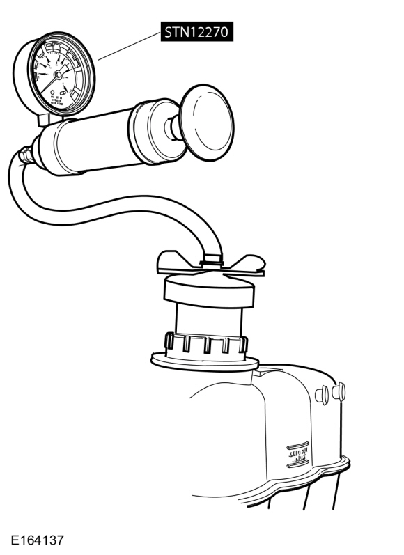
  1. NOTICE: Do not increase the cooling system pressure above the maximum pressure specified in the Specifications table in this section, or the cooling system components may be damaged.

    To build pressure in the engine cooling system, slowly pump the pressure tester plunger and increase the pressure to 124 to 138 kPa (18-20 psi). Observe the gauge reading for approximately 2 minutes. The pressure must not drop during this time. If the pressure drops during this time, check for leaks and repair as necessary.
  2. If no leaks are found and the pressure drops, the leak may be inside the engine. Check the coolant for engine oil and the engine oil for coolant.
    REFER TO: Engine (303-00 Engine System - General Information, Diagnosis and Testing).
  3. If the pressure does not drop, remove the cooling system pressure tester and adapter from the degas bottle.
  4. Install the degas bottle cap until it contacts the stop.

Thermostat

Install a new thermostat only after performing at least one of the following tests and inspections:

  • Precise Test B or C
  • Visual Inspection of the Thermostat

Visual Inspection of the Thermostat

  1. Remove the thermostat.
  2. Inspect the thermostat for signs of damage, including:
  • Valve not fully seated (light visible through the valve)
  • Foreign object lodged in the main valve
  • Bent or broken frame or flange
  • Bent or broken spring
  • Wax leakage from the wax element or a bulge in the element
  • Any other damage or distortion
  1. If damage is found during the inspection, remove all foreign objects or debris and install a new thermostat.

Radiator Leak Test, Removed from the Vehicle

NOTICE: Never leak test an aluminum radiator in the same tank of water in which copper/brass radiators are tested. Fluxes and caustic cleaners may be present in the tank and will damage the aluminum radiator.

  1. Check the radiator for leaks by submerging it in clean water and applying air pressure up to the maximum value specified in the Specifications table.

Test yourself

A quick Ford Escape quiz: every answer comes with an explanation and a link to the manual page.