Electrical

Diagnosis and Testing - Information and Entertainment System

~166min read
2special tools

Diagnostic Trouble Code (DTC) Chart

The diagnosis in this manual assumes a certain level of skill and knowledge of Ford-approved diagnostic procedures.
REFER TO: Diagnostic Methods (100-00 General Information, Description and Operation).


Diagnostic Trouble Code Chart


Module Trouble Code Description Action
ACM B150K: 55 Automotive Audio Bus (A2B) Node 1: Not Configured GO to Pinpoint Test C
ACM B150K:87 Automotive Audio Bus (A2B) Node 1: Missing Message GO to Pinpoint Test C
ACM B150K:8F Automotive Audio Bus (A2B), Node 1: Erroneous GO to Pinpoint Test C
ACM B1511:01 Automotive Audio Bus (A2B) Master Node: General Electrical Failure GO to Pinpoint Test C
ACM B1511:11 Automotive Audio Bus (A2B) Master Node: Short to Ground GO to Pinpoint Test C
ACM B1511:12 Automotive Audio Bus (A2B) Master Node: Short to Battery GO to Pinpoint Test C
ACM B1511:13 Automotive Audio Bus (A2B) Master Node: Open Circuit GO to Pinpoint Test C
ACM B1511:95 Automotive Audio Bus (A2B) Master Node: Incorrect Assembly GO to Pinpoint Test C
ACM B1A01:01 Speaker No. 1: General Electrical Failure GO to Pinpoint Test E
ACM B1A01:11 Speaker No. 1: Short to Ground GO to Pinpoint Test E
ACM B1A01:12 Speaker No. 1: Short to Battery GO to Pinpoint Test E
ACM B1A01:13 Speaker No. 1: Open Circuit GO to Pinpoint Test E
ACM B1A02:01 Speaker No. 2: General Electrical Failure GO to Pinpoint Test E
ACM B1A02:11 Speaker No. 2: Short to Ground GO to Pinpoint Test E
ACM B1A02:12 Speaker No. 2: Short to Battery GO to Pinpoint Test E
ACM B1A02:13 Speaker No. 2: Open Circuit GO to Pinpoint Test E
ACM B1A03:01 Speaker No. 3: General Electrical Failure GO to Pinpoint Test E
ACM B1A03:11 Speaker No. 3: Short to Ground GO to Pinpoint Test E
ACM B1A03:12 Speaker No. 3: Short to Battery GO to Pinpoint Test E
ACM B1A03:13 Speaker No. 3: Open Circuit GO to Pinpoint Test E
ACM B1A04:01 Speaker No. 4: General Electrical Failure GO to Pinpoint Test E
ACM B1A04:11 Speaker No. 4: Short to Ground GO to Pinpoint Test E
ACM B1A04:12 Speaker No. 4: Short to Battery GO to Pinpoint Test E
ACM B1A04:13 Speaker No. 4: Open Circuit GO to Pinpoint Test E
ACM B1A08:13 Speaker No. 8: Open Circuit GO to Pinpoint Test F
ACM B1A09:13 Speaker No. 9: Open Circuit GO to Pinpoint Test F
ACM B1A10:13 Speaker No. 10: Open Circuit GO to Pinpoint Test F
ACM B1A89:11 Satellite Antenna: Short to Ground GO to Pinpoint Test B
ACM B1A89:13 Satellite Antenna: Open Circuit GO to Pinpoint Test B
ACM U0100:00 Lost Communication With ECM/PCM "A": No Sub Type Information GO to Pinpoint Test W
ACM U0121:00 Lost Communication with Anti-Lock Braking System (ABS) Control Module: No Sub-Type Information GO TO Pinpoint Test X
ACM U0140:00 Lost Communication With Body Control Module: No Sub Type Information GO to Pinpoint Test Y
ACM U0155:00 Lost Communication with Instrument Panel Cluster (IPC) Control Module: No Sub Type Information GO to Pinpoint Test Z
ACM U0238:00 Lost communication with audio system digital control module "D": no subtype information GO to Pinpoint Test AC
ACM U0253:00 Lost Communication with Auxiliary Protocol Interface Module: No Sub Type Information GO to Pinpoint Test advertisement
ACM U201A: 51 Control Module Primary Calibration Data: Not Programmed GO to Pinpoint Test AH
ACM U2024:06 Control Module Calibration Data: Algorithm-Based Failure GO to Pinpoint Test AH
ACM U2024:41 Control Module Calibration Data: General Checksum Error GO to Pinpoint Test AH
ACM U2024:44 Control Module Calibration Data: Data Memory Failure GO to Pinpoint Test AH
ACM U2024:51 Control Module Calibration Data: Not Programmed GO to Pinpoint Test AH
ACM U2100:00 Initial Configuration Not Complete: No Sub Type Information GO to Pinpoint Test AH
ACM U2101:00 Control Module Configuration Incompatible: No Sub Type Information GO to Pinpoint Test AH
ACM U3000:41 Control Module: General Checksum Failure GO TO Pinpoint Test AI
ACM U3000:42 Control Module: General Memory Failure GO TO Pinpoint Test AI
ACM U3000:43 Control Module: Special Memory Failure GO TO Pinpoint Test AI
ACM U3000:44 Control Module: Data Memory Failure GO TO Pinpoint Test AI
ACM U3000:45 Control module: software memory failure GO TO Pinpoint Test AI
ACM U3000:46 Control module: calibration / parameter memory failure GO TO Pinpoint Test AI
ACM U3000:51 Control Module: Not Programmed GO TO Pinpoint Test AI
ACM U3000:88 Control Module: Bus Off GO TO Pinpoint Test AI
ACM U3000:92 Control Module: Performance or Incorrect Operation GO TO Pinpoint Test AI
ACM U3000:94 Control Module: Unexpected Operation GO TO Pinpoint Test AI
ACM U3000:96 Control Module: Internal Component Failure GO TO Pinpoint Test AI
ACM U3003:16 Battery Voltage: Circuit Voltage Below Threshold GO TO Pinpoint Test AE
ACM U3003:17 Battery Voltage: Circuit Voltage Above Threshold GO TO Pinpoint Test AF
APIM B1087:01 LIN Bus "A": General Electrical Failure GO to Pinpoint Test H
APIM B108E:01 Display: General Electrical Failure GO to Pinpoint Test J
APIM B108E:01 Display: General Electrical Failure GO to Pinpoint Test K
APIM B108E:02 Display: General Signal Failure GO to Pinpoint Test J
APIM B108E:02 Display: General Signal Failure GO to Pinpoint Test K
APIM B108E: 4A Display: Incorrect Component Installed GO to Pinpoint Test J
APIM B108E: 4A Display: Incorrect Component Installed GO to Pinpoint Test K
APIM B108E: 4B Display: Overheat GO to Pinpoint Test J
APIM B108E: 4B Display: Overheat GO to Pinpoint Test K
APIM B108E: 63 Display: Circuit/Component Protection Time-out GO to Pinpoint Test J
APIM B108E:87 Display: No Sub Type Information GO to Pinpoint Test J
APIM B108E:87 Display: No Sub Type Information GO to Pinpoint Test K
APIM B119F:01 GPS Antenna: General Electrical Failure GO TO Pinpoint Test R
APIM B119F: 13 GPS Antenna: Circuit Open GO TO Pinpoint Test R
APIM B1252:11 USB Port: Short to Ground GO to Pinpoint Test N
APIM B1252:13 USB Port: Circuit Open GO to Pinpoint Test N
APIM B14FD:11 Multimedia External Control Connection: Circuit Short to Ground GO to Pinpoint Test N
APIM B1D79:11 Microphone Input: Short to Ground GO to Pinpoint Test M
APIM B1D79:12 Microphone Input: Short to Battery GO to Pinpoint Test M
APIM B1D79:13 Microphone Input: Circuit Open GO to Pinpoint Test M
APIM U0100:00 Lost Communication With ECM/PCM "A": No Sub Type Information GO to Pinpoint Test W
APIM U0121:00 Lost Communication with Anti-Lock Braking System (ABS) Control Module: No Sub-Type Information GO to Pinpoint Test AK
APIM U0140:00 Lost Communication With Body Control Module: No Sub Type Information GO to Pinpoint Test AK
APIM U0151:00 Lost Communication with Restraints Control Module: No Sub Type Information GO to Pinpoint Test AK
APIM U0155:00 Lost Communication with Instrument Panel Cluster (IPC) Control Module: No Sub Type Information GO to Pinpoint Test AK
APIM U0159:00 Park Assist Control Module "A" Lost Communication: No Sub Type Information GO to Pinpoint Test AK
APIM U0162:00 Navigation Display Module Lost Communication: No Sub Type Information GO to Pinpoint Test J
APIM U0162:00 Navigation Display Module Lost Communication: No Sub Type Information GO to Pinpoint Test K
APIM U0184:00 Lost Communication With Radio: No Sub Type Information GO to Pinpoint Test AK
APIM U0198:00 Telematics Control Module Lost Communication: No Sub Type Information GO to Pinpoint Test AK
APIM U0208:00 "Seat Control Module A" Lost Communication: No Sub Type Information GO to Pinpoint Test AK
APIM U020C:00 Wireless Accessory Charging Module "A" Lost Communication: No Sub Type Information GO to Pinpoint Test AK
APIM U0232:00 Side Obstacle Detection Control Module - Left Lost Communication: No Sub Type Information GO to Pinpoint Test AK
APIM U0233:00 Side Obstacle Detection Control Module - Right Lost Communication: No Sub Type Information GO to Pinpoint Test AK
APIM U0238:00 Lost communication with audio system digital control module "D": no subtype information GO to Pinpoint Test AK
APIM U0293:00 Lost Communication with Hybrid/Electric Transmission Control Module: No Sub Type Information GO to Pinpoint Test AK
APIM U0415:00 Incorrect Data Received from Anti-Lock Braking System (ABS) Control Module: No Sub-Type Information GO to Pinpoint Test AL
APIM U0422:00 Incorrect Data Received from Body Control Module: No Sub Type Information GO to Pinpoint Test AL
APIM U0423:00 Instrument Panel Cluster (IPC) Control Module Received Incorrect Data: No Sub Type Information GO to Pinpoint Test AL
APIM U0452:00 Incorrect Data Received from Restraints Control Module: No Sub Type Information GO to Pinpoint Test AL
APIM U1A00:87 Private Communication Network: No Sub Type Information GO to Pinpoint Test B
APIM U2013:01 Switch Pack: General Electrical Failure GO to Pinpoint Test H
APIM U2013:16 Switch Pack: Circuit Voltage Below Threshold GO to Pinpoint Test H
APIM U2013: 17 Switch Pack: Circuit Voltage Above Threshold GO to Pinpoint Test H
APIM U2013: 63 Switch Pack: Circuit/Component Protection Time-out GO to Pinpoint Test H
APIM U2017: 45 Control Module No. 2 Software: Software Memory Failure GO to Pinpoint Test AM
APIM U2017: 51 Control Module No. 2 Software: Not Programmed GO to Pinpoint Test AM
APIM U2017: 52 Control Module No. 2 Software: Not Activated GO to Pinpoint Test AM
APIM U2017: 54 Control Module No. 2 Software: Calibration Missing GO to Pinpoint Test AM
APIM U2100:00 Initial Configuration Not Complete: No Sub Type Information GO to Pinpoint Test AM
APIM U2101:00 Control Module Configuration Incompatible: No Sub Type Information GO to Pinpoint Test AM
APIM U3000:04 Control Module: Internal System Failure GO to Pinpoint Test AN
APIM U3000:09 Control Module: Component Failure GO to Pinpoint Test AN
APIM U3000:41 Control Module: General Checksum Failure GO to Pinpoint Test AN
APIM U3000:88 Control Module: Bus Off GO to Pinpoint Test AK
APIM U3003:16 Battery Voltage: Circuit Voltage Below Threshold GO TO Pinpoint Test AE
APIM U3003:17 Battery Voltage: Circuit Voltage Above Threshold GO TO Pinpoint Test AF
DSP B13FB:11 Audio Enable Line: Short to Ground GO to Pinpoint Test C
DSP B1A01:01 Speaker No. 1: General Electrical Failure GO to Pinpoint Test G
DSP B1A01:11 Speaker No. 1: Short to Ground GO to Pinpoint Test G
DSP B1A01:12 Speaker No. 1: Short to Battery GO to Pinpoint Test G
DSP B1A01:13 Speaker No. 1: Open Circuit GO to Pinpoint Test G
DSP B1A03:01 Speaker No. 3: General Electrical Failure GO to Pinpoint Test G
DSP B1A03:11 Speaker No. 3: Short to Ground GO to Pinpoint Test G
DSP B1A03:12 Speaker No. 3: Short to Battery GO to Pinpoint Test G
DSP B1A03:13 Speaker No. 3: Open Circuit GO to Pinpoint Test G
DSP B1A04:01 Speaker No. 4: General Electrical Failure GO to Pinpoint Test G
DSP B1A04:11 Speaker No. 4: Short to Ground GO to Pinpoint Test G
DSP B1A04:12 Speaker No. 4: Short to Battery GO to Pinpoint Test G
DSP B1A04:13 Speaker No. 4: Open Circuit GO to Pinpoint Test G
DSP B1A05:01 Speaker No. 5: General Electrical Failure GO to Pinpoint Test G
DSP B1A05:11 Speaker No. 5: Short to Ground GO to Pinpoint Test G
DSP B1A05:12 Speaker No. 5: Short to Battery GO to Pinpoint Test G
DSP B1A05:13 Speaker No. 5: Circuit Open GO to Pinpoint Test G
DSP B1A06:01 Speaker No. 6: General Electrical Failure GO to Pinpoint Test G
DSP B1A06:11 Speaker No. 6: Short to Ground GO to Pinpoint Test G
DSP B1A06:12 Speaker No. 6: Short to Battery GO to Pinpoint Test G
DSP B1A06:13 Speaker No. 6: Circuit Open GO to Pinpoint Test G
DSP U0140:00 Lost Communication With Body Control Module: No Sub Type Information GO to Pinpoint Test Y
DSP U0155:00 Lost Communication with Instrument Panel Cluster (IPC) Control Module: No Sub Type Information GO to Pinpoint Test Z
DSP U0184:00 Lost Communication With Radio: No Sub Type Information GO TO Pinpoint Test AA
DSP U0198:00 Telematics Control Module Lost Communication: No Sub Type Information GO to Pinpoint Test AB
DSP U0253:00 Lost Communication with Auxiliary Protocol Interface Module: No Sub Type Information GO to Pinpoint Test advertisement
DSP U0422:00 Incorrect Data Received from Body Control Module: No Sub Type Information GO to Pinpoint Test AG
DSP U201A: 51 Control Module Primary Calibration Data: Not Programmed GO to Pinpoint Test AH
DSP U2024:41 Control Module Calibration Data: General Checksum Error GO to Pinpoint Test AH
DSP U2024:48 Control Module Calibration Data: Monitoring Software GO to Pinpoint Test AH
DSP U2024:51 Control Module Calibration Data: Not Programmed GO to Pinpoint Test AH
DSP U2100:00 Initial Configuration Not Complete: No Sub Type Information GO to Pinpoint Test AH
DSP U2101:00 Control Module Configuration Incompatible: No Sub Type Information GO to Pinpoint Test AH
DSP U3000:41 Control Module: General Checksum Failure GO TO Pinpoint Test AI
DSP U3000:42 Control Module: General Memory Failure GO TO Pinpoint Test AI
DSP U3003:16 Battery Voltage: Circuit Voltage Below Threshold GO TO Pinpoint Test AE
DSP U3003:17 Battery Voltage: Circuit Voltage Above Threshold GO TO Pinpoint Test AF
SCCM B137F: 11 Left Steering Wheel Switch Pack: Short to Ground GO to Pinpoint Test I
SCCM B137F: 13 Left Steering Wheel Switch Pack: Open Circuit GO to Pinpoint Test I
SCCM B137F: 96 Left Steering Wheel Switch Pack: Internal Component Failure GO to Pinpoint Test I
SCCM B137F: 9E Left Steering Wheel Switch Pack: Stuck On GO to Pinpoint Test I
SCCM B1380:11 Right Steering Wheel Switch Pack: Short to Ground GO to Pinpoint Test I
SCCM B1380:13 Right Steering Wheel Switch Pack: Circuit Open GO to Pinpoint Test I
SCCM B1380:96 Right Steering Wheel Switch Pack: Internal Component Failure GO to Pinpoint Test I
SCCM B1380:9E Right Steering Wheel Switch Pack: Stuck On GO to Pinpoint Test I
TCU B1246:11 GSM (Global System for Mobile Communications) Antenna: Short to Ground GO to Pinpoint Test S
TCU B1246:13 GSM (Global System for Mobile Communications) Antenna: Circuit Open GO to Pinpoint Test S
TCU B156D: 55 TCU Client Connection Settings Sync with HMI: Not Configured GO to Pinpoint Test AH
TCU B156D: 89 TCU Client Connection Settings Sync with HMI: ISO/SAE Reserved GO to Pinpoint Test AH
TCU B1D55:11 Antenna No. 2: Short to Ground GO TO Pinpoint Test T
TCU B1D55:13 Antenna No. 2: Circuit Open GO TO Pinpoint Test T
TCU U0100:00 Lost Communication With ECM/PCM "A": No Sub Type Information GO to Pinpoint Test W
TCU U0140:00 Lost Communication With Body Control Module: No Sub Type Information GO to Pinpoint Test Y
TCU U0253:00 Lost Communication with Auxiliary Protocol Interface Module: No Sub Type Information GO to Pinpoint Test advertisement
TCU U0422:00 Incorrect Data Received from Body Control Module: No Sub Type Information GO to Pinpoint Test AG
TCU U0554:00 Invalid Data Received from Auxiliary Protocol Interface Module: No Sub Type Information GO to Pinpoint Test AG
TCU U2024:00 Control Module Calibration Data: No Sub Type Information GO to Pinpoint Test AH
TCU U2100:00 Initial Configuration Not Complete: No Sub Type Information GO to Pinpoint Test AH
TCU U2101:00 Control Module Configuration Incompatible: No Sub Type Information GO to Pinpoint Test AH
TCU U3000:04 Control Module: Internal System Failure GO TO Pinpoint Test AJ
TCU U3000:09 Control Module: Component Failure GO TO Pinpoint Test AJ
TCU U3000:41 Control Module: General Checksum Failure GO TO Pinpoint Test AI
TCU U3000:42 Control Module: General Memory Failure GO TO Pinpoint Test AI
TCU U3000:52 Control Module: Not Activated GO TO Pinpoint Test AJ
TCU U3000:56 Control Module: Incorrect/Incompatible Configuration GO TO Pinpoint Test AI
TCU U3003:16 Battery Voltage: Circuit Voltage Below Threshold GO TO Pinpoint Test AE
TCU U3003:17 Battery Voltage: Circuit Voltage Above Threshold GO TO Pinpoint Test AF

Symptom Charts

Symptom Chart: Radio

The diagnosis in this manual assumes a certain level of skill and knowledge of Ford-approved diagnostic procedures.
REFER TO: Diagnostic Methods (100-00 General Information, Description and Operation).

Condition Action
Module Does Not Respond to Diagnostic Scan Tool
REFER TO: Communication Network (418-00 Communication Network, Diagnosis and Testing).
AM Radio Inoperative. GO to Pinpoint Test A
FM Radio Inoperative GO to Pinpoint Test A
Poor AM Reception GO to Pinpoint Test A
Poor FM Reception GO to Pinpoint Test A
Continuous Seek or Scan in AM/FM Mode GO to Pinpoint Test A
Poor Satellite Radio Reception GO to Pinpoint Test B
Poor Satellite Radio Sound Quality or No Sound During Satellite Radio Mode - All Other Functions Operate Correctly GO to Pinpoint Test B
Satellite Radio Inoperative or Operates Incorrectly GO to Pinpoint Test B
Audio System Does Not Operate Correctly From the Radio Control Panel GO to Pinpoint Test H
One or More Audio System Steering Wheel Control Buttons Inoperative. GO to Pinpoint Test I
Unable to Change Audio Source GO to Pinpoint Test C
Audio System Off Displayed at Regular Intervals GO to Pinpoint Test C

Symptom Chart: Speakers and Sound Quality - 6 Speaker System

The diagnosis in this manual assumes a certain level of skill and knowledge of Ford-approved diagnostic procedures.
REFER TO: Diagnostic Methods (100-00 General Information, Description and Operation).

Condition Action
No Sound From All Speakers GO to Pinpoint Test C
Left Speakers Inoperative When Using Bluetooth and SYNC USB Hub Functions. GO to Pinpoint Test L
Right Speakers Inoperative When Using Bluetooth and SYNC USB Hub Functions. GO to Pinpoint Test L
Poor Sound Quality or Distorted Sound From One or More Speakers (Not All Speakers) GO to Pinpoint Test D
Left instrument panel speaker inoperative GO to Pinpoint Test E
Right instrument panel speaker inoperative GO to Pinpoint Test E
Left front door woofer inoperative GO to Pinpoint Test E
Right front door woofer inoperative GO to Pinpoint Test E
Left rear door woofer inoperative GO to Pinpoint Test E
Right rear door woofer inoperative GO to Pinpoint Test E

Symptom Chart: Speakers and Sound Quality - 10-Speaker System

The diagnosis in this manual assumes a certain level of skill and knowledge of Ford-approved diagnostic procedures.
REFER TO: Diagnostic Methods (100-00 General Information, Description and Operation).

Condition Action
No Sound From All Speakers GO to Pinpoint Test C
Left Speakers Inoperative When Using Bluetooth and SYNC USB Hub Functions. GO to Pinpoint Test L
Right Speakers Inoperative When Using Bluetooth and SYNC USB Hub Functions. GO to Pinpoint Test L
Poor Sound Quality or Distorted Sound From One or More Speakers (Not All Speakers) GO to Pinpoint Test D
Center instrument panel speaker inoperative GO to Pinpoint Test F
Left instrument panel speaker inoperative GO to Pinpoint Test F
Right instrument panel speaker inoperative GO to Pinpoint Test F
Left front door woofer inoperative GO to Pinpoint Test G
Right front door woofer inoperative GO to Pinpoint Test G
Left rear door tweeter inoperative. GO to Pinpoint Test G
Right rear door tweeter inoperative GO to Pinpoint Test G
Left rear door woofer inoperative GO to Pinpoint Test G
Right rear door woofer inoperative GO to Pinpoint Test G
Subwoofer speaker inoperative GO to Pinpoint Test G

Symptom Chart: Display Unit - Non-Touchscreen

The diagnosis in this manual assumes a certain level of skill and knowledge of Ford-approved diagnostic procedures.
REFER TO: Diagnostic Methods (100-00 General Information, Description and Operation).

Condition Action
Display blank or black GO to Pinpoint Test J
One or more display buttons inoperative GO to Pinpoint Test J
Display unit image incorrect, image color incorrect, or image distorted, flickering or blurred GO to Pinpoint Test J
Display unit image frozen or stuck GO to Pinpoint Test J

Symptom Chart: Display Unit - Touchscreen

The diagnosis in this manual assumes a certain level of skill and knowledge of Ford-approved diagnostic procedures.
REFER TO: Diagnostic Methods (100-00 General Information, Description and Operation).

Condition Action
Display blank or black GO to Pinpoint Test K
Display does not respond to touch GO to Pinpoint Test K
Display responds slowly to touch GO to Pinpoint Test K
Display unit image incorrect, image color incorrect, or image distorted, flickering or blurred GO to Pinpoint Test K
Display unit image frozen or stuck GO to Pinpoint Test K

Symptom Chart: SYNC Features/Media/Phone

The diagnosis in this manual assumes a certain level of skill and knowledge of Ford-approved diagnostic procedures.
REFER TO: Diagnostic Methods (100-00 General Information, Description and Operation).

Condition Action
SYNC does not operate properly from the radio control panel. GO to Pinpoint Test H
One or more SYNC steering wheel control buttons inoperative. GO to Pinpoint Test I
Left speakers inoperative when using Bluetooth and SYNC Media Center functions. GO to Pinpoint Test L
Right speakers inoperative when using Bluetooth and SYNC Media Center functions. GO to Pinpoint Test L
SYNC voice prompts inoperative or operate incorrectly GO to Pinpoint Test L
Incoming audio not heard in the vehicle during a phone call GO to Pinpoint Test L
Poor sound quality, distortion or no sound in SYNC mode GO to Pinpoint Test L
Voice commands inoperative or outgoing audio not transmitted during a phone call GO to Pinpoint Test M
Individual Bluetooth device or feature inoperative GO to Pinpoint Test P
Unable to pair Bluetooth device or Bluetooth feature inoperative GO TO Pinpoint Test O
USB device not recognized by SYNC or audio files on USB device not found by SYNC from one or both USB ports. GO to Pinpoint Test N
911 Assist or Emergency Assistance Not Operational message displayed. GO to Pinpoint Test Q
SYNC AppLink inoperative or operates incorrectly GO to Pinpoint Test U
SYNC Connect inoperative or operates incorrectly GO to Pinpoint Test S
Android Auto™ or Apple CarPlay™ inoperative GO to Pinpoint Test V
Vehicle Wi-Fi hotspot inoperative, has slow data speed or cannot transmit any data GO TO Pinpoint Test T

Symptom Chart: Navigation/Compass

The diagnosis in this manual assumes a certain level of skill and knowledge of Ford-approved diagnostic procedures.
REFER TO: Diagnostic Methods (100-00 General Information, Description and Operation).

Condition Action
Compass inoperative or operates incorrectly GO TO Pinpoint Test R
Navigation inoperative or operates incorrectly GO TO Pinpoint Test R
SIRIUS Travel Link™ or digital radio link inoperative GO to Pinpoint Test B

Pinpoint Tests


PINPOINT TEST A: POOR AM (AMPLITUDE MODULATION) - FM (FREQUENCY MODULATION) RECEPTION

For wiring diagrams and connector information, refer to Cell 130 Wiring Diagrams.

Normal Operation and Fault Symptoms

REFER TO: Information and Entertainment System - Component Location (415-00 Information and Entertainment System - General Information, Description and Operation).
REFER TO: Information and Entertainment System - Overview (415-00 Information and Entertainment System - General Information, Description and Operation).
REFER TO: Information and Entertainment System - System Operation and Component Description (415-00 Information and Entertainment System - General Information, Description and Operation).

Audio Unit Coaxial Cable Connection


Item Part Number Description
1 — AM/FM1 Antenna Connection
2 — FM2 Diversity Antenna Connection
3 — Satellite Radio

Possible Sources

  • Wiring, Terminals or Connectors
  • Ignition System
  • Noise Suppression Device
  • Generator
  • Antenna Cable
  • Antenna Amplifier
  • Glass Antenna Grid
  • ACM

Visual Inspection and Pre-checks

  • Inspect the glass antenna grid for damage.
A1 CHECK AUDIO SYSTEM RECEPTION WITH REAR WINDOW DEFROST ON
  • Ignition OFF.
  • Operate the audio system in AM/FM mode.
  • Monitor radio reception.
  • NOTE: Non-hybrid vehicles require the engine to be running to turn on the rear window defrost. Hybrid vehicles require the vehicle to be in Ready-to-Drive mode. Turn on the rear window defrost function and monitor radio reception.

Is poor reception present only when the rear window defrost is on?
Yes For non-hybrid vehicles, GO to A2
For hybrid vehicles, GO to A3
No GO to A6
A2 CHECK AUDIO SYSTEM RECEPTION WITH ENGINE RUNNING AND REAR WINDOW DEFROST OFF
  • Start the engine.
  • NOTE: Make sure the rear window defrost function is turned off. Do not activate it. Operate the audio system in AM/FM mode.

Is poor reception present when the rear window defrost is off?
Yes GO to A4
No GO to A3
A3 CHECK REAR WINDOW DEFROST GRID FOR PROPER OPERATION
  • Check the operation of the rear window defrost grid. Make sure all grid lines operate correctly.

Does the rear window defrost grid operate correctly?
Yes INSTALL a new noise suppression device on the rear window defrost grid connection.
REFER TO: Antenna Isolator Module (415-00 Information and Entertainment System - General Information, Removal and Installation).
No
REFER TO: Glass, Frame and Mechanisms - Vehicles With: One-Touch Up and Down Front Windows (501-11 Glass, Frame and Mechanisms, Diagnosis and Testing).
REFER TO: Glass, Frame and Mechanisms - Vehicles With: One-Touch Down Driver Window (501-11 Glass, Frame and Mechanisms, Diagnosis and Testing).
A4 CHECK THE GENERATOR
  • Ignition OFF.
  • Disconnect the generator "B" connector.
  • NOTE: Do not increase engine speed above idle speed. Start the engine.
  • NOTE: Do not increase engine speed above idle speed. Incorrect test results may be obtained if engine speed exceeds idle. Only with the engine running at idle, turn on the audio system in AM/FM mode.

Is reception normal?
Yes INSTALL a new generator. REFER TO the appropriate removal and installation procedure in Section 414-02.
No GO to A5
A5 CHECK THE IGNITION CIRCUITS
  • Ignition OFF.
  • Connect the generator "A" connector.
  • Inspect the engine compartment and make sure that all ignition coils are correctly and securely connected. Check the coil housings for cracks.
  • Inspect all wiring harnesses and connectors for damaged insulation, loose retainers or breaks.

Are the ignition components normal?
Yes USE a jumper cable to ground the various parts of the vehicle to the frame (for example: engine, fenders, side panels, rock deflectors, air cleaner and body sheet metal). When the noise is eliminated, PROVIDE a permanent ground where necessary.
No REPAIR the ignition system as necessary.
A6 CHECK THE WINDSHIELD ANTENNA GRID
  • Ignition OFF.
  • Inspect the connection to the antenna amplifier and the glass antenna grid for damage.

Is the connection to the antenna amplifier good, and the glass antenna grid undamaged?
Yes GO to A7
No REPAIR the connection to the antenna amplifier or the glass grid as necessary.
A7 CHECK THE ACM (AUDIO SYSTEM FRONT MODULE) ANTENNA VOLTAGE OUTPUT
  • Ignition OFF.
  • Disconnect the AM/FM 1 antenna cable from the ACM.
  • The ignition is on.
  • NOTE: Refer to the schematic at the beginning of this test to identify the correct cable connection to the ACM. Using flexible probe 300-08058 (0.5 mm x 0.5 mm) or equivalent, measure:

    AM / FM 1 Antenna Cable


    Positive lead Measurement/Action Negative lead
    AM/FM 1 antenna cable wire at the ACM (component side) Ground

Is the voltage greater than 11 volts?
Yes GO to A8
No GO to A10
A8 CHECK THE VOLTAGE AT THE ANTENNA AMPLIFIERS
  • Ignition OFF.
  • Connect the AM/FM 1 antenna cable to the ACM.
  • Disconnect the antenna cable from the AM/FM 1 antenna amplifier.
  • The ignition is on.
  • Action:

    AM / FM 1 Antenna Cable


    Positive lead Measurement/Action Negative lead
    antenna cable wire at the AM/FM 1 antenna amplifier Ground

Is the voltage greater than 11 volts?
Yes GO to A9
No IDENTIFY the antenna cable with an open or short circuit. INSTALL a new cable.
REFER TO: Audio Unit Antenna Cable (415-00 Information and Entertainment System - General Information, Removal and Installation).
A9 AM (AMPLITUDE MODULATION) / FM (FREQUENCY MODULATION) 1 ANTENNA AMPLIFIER ISOLATION
  • Ignition OFF.
  • Connect the antenna cable to the FM 2 diversity antenna amplifier (if equipped).
  • Install a new AM/FM 1 antenna amplifier.
    REFER TO: AM/FM 1 Antenna Amplifier (415-00 Information and Entertainment System - General Information, Removal and Installation).
  • Operate the audio system in AM/FM mode.

Is reception normal?
Yes The system operates correctly. The antenna amplifier was the concern.
No GO to A10
A10 CHECK THE ACM (AUDIO SYSTEM FRONT MODULE) OPERATION
  • Ignition OFF.
  • Disconnect and inspect all ACM connectors.
  • Repair:
    • Corrosion (clean the module terminals or install new connectors or terminals)
    • Damaged or bent terminals (install new terminals or pins)
    • Backed-out pins (install new pins as necessary)
  • Connect the ACM connectors. Make sure they are fully seated and locked.
  • Operate the system and determine if the concern is still present.

Is the concern still present?
Yes CHECK OASIS for any applicable service articles: TSB, GSB, SSM or FSA. If a service article exists for this concern, DISCONTINUE this test and FOLLOW the service article instructions. If no service article resolves this concern, INSTALL a new ACM.
REFER TO: Front Audio Control Module (ACM) (415-00 Infotainment System - General Information, Removal and Installation).
No The system is currently operating correctly. The concern may have been caused by module connections. ADDRESS the root cause of any connector or terminal issues.
PINPOINT TEST B: SATELLITE RADIO/SIRIUS TRAVEL LINK™/DIGITAL RADIO DATA LINK CONCERN

For wiring diagrams and connector information, refer to Cell 130 Wiring Diagrams.

Normal Operation and Fault Symptoms

REFER TO: Information and Entertainment System - Component Location (415-00 Information and Entertainment System - General Information, Description and Operation).
REFER TO: Information and Entertainment System - Overview (415-00 Information and Entertainment System - General Information, Description and Operation).
REFER TO: Information and Entertainment System - System Operation and Component Description (415-00 Information and Entertainment System - General Information, Description and Operation).

When the satellite radio subscription is active, the satellite radio ESN built into the ACM is associated with the VIN.

Audio Unit Coaxial Cable Connection


Item Part Number Description
1 — AM/FM1 Antenna Connection
2 — FM2 Diversity Antenna Connection
3 — Satellite Radio

DTC Fault Trigger Conditions

Trouble Code Description Fault Trigger Condition
ACM B1A89:11 Satellite Antenna: Short to Ground Stored in continuous memory or during an on-demand self-test when the ACM detects a short to ground in the satellite radio cable.
ACM B1A89:13 Satellite Antenna: Open Circuit Stored in continuous memory or during an on-demand self-test when the ACM detects an open in the satellite radio cable.
APIM U1A00:87 Private Communication Network: No Sub Type Information Stored during an on-demand self-test when the APIM does not receive a valid response from the ACM over the SDL circuits.

Possible Sources

  • Subscription expired
  • Compass concern
  • Obstructions in the antenna line of sight
  • Incorrect ESN match
  • Wiring, Terminals or Connectors
  • Satellite radio antenna lower cable (includes GPS splitter)
  • Satellite radio antenna
  • ACM
  • APIM
B1 CHECK FOR DTC (DIAGNOSTIC TROUBLE CODE) U1A00:87
  • The ignition is on.
  • Using the diagnostic scan tool, perform the APIM self-test.

Is DTC U1A00:87 present?
Yes GO TO B15
No For vehicles equipped with satellite radio, GO to B2.
For vehicles not equipped with satellite radio, GO to B13.
B2 CHECK CHANNEL 184
  • Select channel 184.

Does the satellite radio system receive channel 184 with normal sound quality?
Yes GO to B3
No GO to B9
B3 CHECK THE ACTIVE SUBSCRIPTION
  • For Sirius Radio, operate the audio system in satellite radio mode and observe the display.
  • To obtain information about Sirius Travel Link™, refer to the "Subscription Information" item in the SIRIUS Travel Link™ menu.

Does the display show that the subscription has expired?
Yes GO to B4
No If the satellite radio concern persists, GO to B6.
To contact SIRIUS Travel Link™, GO to B7.
B4 CHECK THE VEHICLE SERVICE HISTORY FOR ACM (AUDIO SYSTEM FRONT MODULE) REPLACEMENT
  • Review the vehicle service history and determine whether the ACM was replaced.

Does the vehicle service history indicate a recent ACM replacement?
Yes GO to B5
No The subscription has expired. ADVISE the vehicle owner to contact SIRIUS to reactivate the subscription.
B5 VERIFY THE VIN (VEHICLE IDENTIFICATION NUMBER) AND ESN (ELECTRONIC SERIAL NUMBER) IN THE FILE MATCH THE VIN (VEHICLE IDENTIFICATION NUMBER) AND ESN (ELECTRONIC SERIAL NUMBER) FROM THE VEHICLE
  • Obtain the satellite radio ESN by tuning to channel 0.
  • Contact SIRIUS dealer support.
  • Make sure the SIRIUS VIN and ESN in the customer file match the VIN and ESN received from the vehicle.

Do the VIN and ESN in the SIRIUS customer file match the ESN and VIN received from the vehicle?
Yes The subscription has expired. ADVISE the vehicle owner to contact SIRIUS to reactivate the subscription.
No ADVISE the vehicle owner to contact SIRIUS to update the VIN and ESN received from the vehicle.
B6 VERIFY THE VIN (VEHICLE IDENTIFICATION NUMBER) AND ESN (ELECTRONIC SERIAL NUMBER) IN THE FILE MATCH THE VIN (VEHICLE IDENTIFICATION NUMBER) AND ESN (ELECTRONIC SERIAL NUMBER) FROM THE VEHICLE
  • Obtain the satellite radio ESN by tuning to channel 0.
  • Contact SIRIUS dealer support.
  • Make sure the SIRIUS VIN and ESN in the file match the VIN and ESN received from the vehicle.
  • Drive the vehicle to an open area free of obstructions, such as tall buildings or large trees.
  • Operate the audio system in satellite radio mode.
  • NOTE: Activation may take up to 30 minutes for the signal to be received and for the satellite radio functions to operate. Request SIRIUS to send the activation signal to the vehicle 2-3 times.
  • Operate multiple channels of the audio system in satellite radio mode.

Does the satellite radio system receive multiple channels with normal sound quality?
Yes The system is operating correctly. The concern may have been caused by the SIRIUS file information not matching the vehicle, or by the need to resend the activation signal.
No GO to B11
B7 SEND THE SIRIUS ACTIVATION SIGNAL AND RECHECK THE SIRIUS TRAVEL LINK™ OPERATION
  • Access the SIRIUS website and enter the ESN to send the activation signal to the vehicle.
  • Wait 15 minutes.
  • NOTE: If the SIRIUS Travel Link™ features have not updated, enter the ESN again to resend/update the signal. Operate the various SIRIUS Travel Link™ features and verify operation.

Is the SIRIUS Travel Link™ operating correctly?
Yes The system is currently operating correctly.
No GO to B8
B8 ALLOW THE CATEGORY UPDATE AND CHECK THE SIRIUS TRAVEL LINK™ OPERATION
  • Drive the vehicle to an open area, clear of obstructions such as tall buildings and large trees.
  • Operate the various SIRIUS Travel Link™ features and verify operation.

Is the SIRIUS Travel Link™ operating correctly?
Yes The system is currently operating correctly. The concern was related to obstructions in the line of sight of the antenna.
No GO to B11
B9 CHECK THE ACM (FRONT AUDIO CONTROL MODULE) OUTPUT VOLTAGE AT THE SATELLITE RADIO ANTENNA CABLE
  • Ignition OFF.
  • Disconnect the satellite radio antenna cable from the ACM.
  • The ignition is on.
  • NOTE: Refer to the schematic at the beginning of this test to identify the correct cable connection to the ACM. Using the 300-08058 female flexible probe (0.5 mm x 0.5 mm) or equivalent, measure:
    Positive lead Measurement/Action Negative lead
    Satellite cable core (component side) Ground

Is the voltage between 4.7 and 5.8 volts?
Yes GO to B10
No GO TO B19
B10 CHECK THE VOLTAGE AT THE SATELLITE RADIO/GPS (GLOBAL POSITIONING SYSTEM) ANTENNA
  • Ignition OFF.
  • Connect the satellite radio antenna cable to the ACM.
  • Disconnect the satellite radio antenna cable from the GPS/satellite antenna.
  • The ignition is on.
  • Using the 300-08058 female flexible probe (0.5 mm x 0.5 mm) or equivalent, measure:
    Positive lead Measurement/Action Negative lead
    Satellite radio/GPS antenna cable wire at the antenna, cavity 1 Ground

Is the voltage between 4.7 and 5.8 volts?
Yes GO to B11
No IDENTIFY the open or shorted cable. INSTALL a new GPS cable for the affected circuit.
REFER TO: Satellite Radio/Global Positioning System (GPS) Antenna Cable (415-00 Information and Entertainment System - General Information, Removal and Installation).
REFER TO: Satellite Radio/Global Positioning System (GPS) Splitter / Cable (415-00 Information and Entertainment System - General Information, Removal and Installation).
B11 DISCONNECT THE SATELLITE RADIO/GPS (GLOBAL POSITIONING SYSTEM) ANTENNA SPLITTER CABLE
  • Disconnect the satellite radio antenna cable from the GPS/satellite antenna.
  • INSTALL a new satellite radio/GPS antenna splitter cable.
    REFER TO: Satellite Radio/Global Positioning System (GPS) Splitter/Cable (415-00 Information and Entertainment System - General Information, Removal and Installation).
  • If the concern is with satellite radio, verify satellite radio operation.
  • If the concern is with SIRIUS Travel Link™, verify SIRIUS Travel Link™ operation.

Is the system operating correctly?
Yes The system is operating correctly. The concern was caused by the original satellite radio/GPS antenna splitter cable.
No GO to B12
B12 CHECK THE ANTENNA BASE AND MOUNTING SURFACE
  • Remove the GPS/satellite radio antenna.
    REFER TO: Satellite Radio/Global Positioning System (GPS) Antenna (415-00 Information and Entertainment System - General Information, Removal and Installation).
  • Inspect the antenna base and the vehicle mounting surface for corrosion.

Is the antenna base and mounting free of corrosion?
Yes GO to B14
No REPAIR any corrosion on the antenna base and/or the vehicle mounting surface. INSTALL the antenna and make sure the specified torque value is used when tightening the fasteners.
B13 CHECK THAT THE COMPASS OPERATES CORRECTLY
  • The ignition is on.
  • Check the compass operation and make sure it operates correctly.

Is the compass operating correctly?
Yes GO to B14
No GO TO Pinpoint Test R
B14 DISCONNECT THE SATELLITE RADIO/GPS (GLOBAL POSITIONING SYSTEM) ANTENNA
  • INSTALL a new GPS/satellite radio antenna.
    REFER TO: Satellite Radio/Global Positioning System (GPS) Antenna (415-00 Information and Entertainment System - General Information, Removal and Installation).
  • If the concern is with satellite radio, verify satellite radio operation.
  • If the concern is with SIRIUS Travel Link™, verify SIRIUS Travel Link™ operation.

Is the system operating correctly?
Yes The system is operating correctly. The concern was caused by the original satellite radio/GPS antenna.
No GO TO B15
B15 CHECK THE SDL (SIRIUS DATA LINK) CIRCUITS FOR A SHORT TO GROUND
  • Ignition OFF.
  • Disconnect the APIM C2383A.
  • Disconnect the ACM C240A and C240B.
  • Action:
    Click to display the connectors
    Positive lead Measurement/Action Negative lead
    C2383A-27 Ground
    C2383A-28 Ground
    C2383A-51 Ground
    C2383A-52 Ground

Is the resistance greater than 10000 ohms?
Yes GO TO B16
No REPAIR the faulty circuit.
B16 CHECK THE SDL (SIRIUS DATA LINK) CIRCUITS FOR A SHORT TO VOLTAGE
  • The ignition is on.
  • Action:
    Click to display the connectors
    Positive lead Measurement/Action Negative lead
    C2383A-27 Ground
    C2383A-28 Ground
    C2383A-51 Ground
    C2383A-52 Ground

Is there voltage present?
Yes REPAIR the faulty circuit.
No GO TO B17
B17 CHECK THE SDL (SIRIUS DATA LINK) CIRCUITS FOR A SHORT TO SHORT
  • Ignition OFF.
  • Action:
    Click to display the connectors
    Positive lead Measurement/Action Negative lead
    C2383A-27 C2383A-28
    C2383A-51 C2383A-52

Is the resistance greater than 10000 Ohms?
Yes GO TO B18
No REPAIR the circuits.
B18 CHECK THE SDL (SIRIUS DATA LINK) CIRCUITS FOR AN OPEN
  • Action:
    Click to display the connectors

    ACM C240A


    Positive lead Measurement/Action Negative lead
    C2383A-27 C240A-14
    C2383A-28 C240A-25

    Click to display the connectors

    ACM C240B


    Positive lead Measurement/Action Negative lead
    C2383A-51 C240B-18
    C2383A-52 C240B-29

Is the resistance less than 3 ohms?
Yes GO TO B19
No REPAIR the faulty circuit.
B19 CHECK THE ACM (FRONT AUDIO CONTROL MODULE) OPERATION
  • The ignition is on.
  • Disconnect and inspect all ACM connectors.
  • Repair:
    • Corrosion (clean the module terminals or install new connectors or terminals)
    • Damaged or bent terminals (install new terminals or pins)
    • Backed-out pins (install new pins as necessary)
  • Connect the ACM connectors. Make sure they are fully seated and locked.
  • Operate the system and determine if the concern is still present.

Is the concern still present?
Yes CHECK OASIS for any applicable service articles: TSB, GSB, SSM or FSA. If a service article exists for this concern, DISCONTINUE this test and FOLLOW the service article instructions. If no service article resolves this concern, INSTALL a new ACM.
REFER TO: Front Audio Control Module (ACM) (415-00 Information and Entertainment System - General Information, Removal and Installation). CHECK the system for normal operation. If the concern persists, GO to B20.
No The system is currently operating correctly. The concern may have been caused by module connections. ADDRESS the root cause of any connector or terminal issues.
B20 CHECK THE APIM (SYNC MODULE) OPERATION
  • Ignition OFF.
  • Disconnect and inspect the APIM connector.
  • Repair:
    • Corrosion (clean the module terminals or install new connectors or terminals)
    • Damaged or bent terminals (install new terminals or pins)
    • Backed-out pins (install new pins as necessary)
  • Reconnect the APIM connector. Make sure it is properly seated and latched.
  • Operate the system and determine if the concern is still present.

Is the concern still present?
Yes CHECK OASIS for any applicable service articles: TSB, GSB, SSM or FSA. If a service article exists for this concern, DISCONTINUE this test and FOLLOW the service article instructions. If no service article resolves this concern, GO to Pinpoint Test AN.
No The system is currently operating correctly. The concern may have been caused by module connections. ADDRESS the root cause of any connector or terminal issues.
PINPOINT TEST C: NO SOUND FROM ALL SPEAKERS

For wiring diagrams and connector information, refer to Cell 130 Wiring Diagrams.

Normal Operation and Fault Symptoms

REFER TO: Infotainment System - System Operation and Component Description (415-00 Infotainment System - General Information, Description and Operation).

A short circuit to ground or voltage in the circuit of one of the speakers may cause several speakers to lose sound due to the built-in ACM overload protection feature. In this case, a speaker DTC is set.

DTC Fault Trigger Conditions

Trouble Code Description Fault Trigger Condition
ACM B150C: 55 Automotive Audio Bus (A2B) Node 1: Not Configured Stored in continuous memory when the ACM detects a fault while attempting to configure the DSP audio module as Slave 1.
ACM B150C: 87 Automotive Audio Bus (A2B) Node 1: Missing Message Stored in permanent memory and during self-test when the ACM detects a fault while attempting to communicate with the DSP audio module.
ACM B150C: 8F Automotive Audio Bus (A2B), Node 1: Erroneous Stored in continuous memory when the ACM detects a fault while attempting to communicate with the DSP audio module.
ACM B1511:01 Automotive Audio Bus (A2B) Master Node: General Electrical Failure Stored in permanent memory and during self-test when the ACM detects a fault while attempting to communicate with the DSP audio module.
ACM B1511:11 Automotive Audio Bus (A2B) Master Node: Short to Ground Stored in permanent memory and during self-test when the ACM detects a short to ground on the automotive audio bus (A2B).
ACM B1511:12 Automotive Audio Bus (A2B) Master Node: Short to Battery Stored in permanent memory and during self-test when the ACM detects a short to voltage on the automotive audio bus (A2B) power supply.
ACM B1511:13 Automotive Audio Bus (A2B) Master Node: Open Circuit Stored in permanent memory and during self-test when the ACM detects an open in the automotive audio bus (A2B) cable.
ACM B1511:95 Automotive Audio Bus (A2B) Master Node: Incorrect Assembly Stored in permanent memory and during self-test when the ACM detects a crossed A2B cable circuit.
DSP B13FB:11 Audio Enable Line: Short to Ground Stored in permanent memory when the DSP does not detect the correct voltage signal from the ignition feed circuit 5 seconds after receiving the RUN ignition mode message from the BCM.

Possible Sources

  • Network communication fault
  • Wiring, Terminals or Connectors
  • Automotive Audio Bus (A2B) Cable
  • Module Configuration
  • DSP
  • ACM
C1 CHECK THE ACM (FRONT AUDIO SYSTEM CONTROL MODULE) PASSES NETWORK TEST
  • The ignition is on.
  • Using the diagnostic scan tool, perform the network test.

Does the ACM pass the network test?
Yes GO to C2
No
REFER TO: Communication Network (418-00 Communication Network, Diagnosis and Testing).
C2 CHECK THE APIM (SYNC MODULE) PASSES NETWORK TEST
  • Review the network test results.

Does the APIM pass the network test?
Yes If the system has 6 speakers, GO to C4.
If the system has 10 speakers, GO to C3.
No
REFER TO: Communication Network (418-00 Communication Network, Diagnosis and Testing).
C3 CHECK THE DSP (DIGITAL SOUND PROCESSING MODULE) PASSES NETWORK TEST
  • Review the network test results.

Does the DSP pass the network test?
Yes GO TO C4
No
REFER TO: Communication Network (418-00 Communication Network, Diagnosis and Testing).
C4 CHECK THE APIM (SYNC MODULE) DIAGNOSTIC TROUBLE CODES (DTCS)
  • Using the diagnostic scan tool, perform the APIM self-test.

Are any diagnostic trouble codes (DTCs) present?
Yes REFER to the DTC Chart in this section.
No GO to C5
C5 CHECK THE ACM (FRONT AUDIO SYSTEM CONTROL MODULE) DIAGNOSTIC TROUBLE CODES (DTCS)
  • Using the diagnostic scan tool, perform the ACM self-test.

Are any diagnostic trouble codes (DTCs) present?
Yes For any automotive audio bus (A2B) DTC, GO to C13.
For all other diagnostic trouble codes (DTCs), REFER to the DTC chart in this section.
No If the system has 6 speakers, GO to C16.
If the system has 10 speakers, GO to C6.
C6 CHECK THE DSP (DIGITAL SOUND PROCESSING MODULE) SPEAKER-RELATED DIAGNOSTIC TROUBLE CODES (DTCS)
  • Using the diagnostic scan tool, perform the DSP self-test.

Are there any speaker-related diagnostic trouble codes (DTCs)?
Yes GO to Pinpoint Test G
No GO TO C7
C7 CHECK THE DSP (DIGITAL SOUND PROCESSING MODULE) ENERGIZE THE CIRCUIT FOR CORRECT VOLTAGE
  • Ignition OFF.
  • Disconnect DSP C3145B.
  • The ignition is on.
  • Turn on the audio system.
  • Action:
    Click to display the connectors
    Positive lead Measurement/Action Negative lead
    C3145B-3 Ground

Is the voltage between 3.5 and 7 volts?
Yes GO TO C12
No GO TO C8
C8 CHECK THE DSP (DIGITAL SOUND PROCESSING MODULE) ENERGIZE THE CIRCUIT FOR A SHORT TO GROUND
  • Ignition OFF.
  • Disconnect ACM C240B.
  • Action:
    Click to display the connectors
    Positive lead Measurement/Action Negative lead
    C3145B-3 Ground

Is the resistance greater than 10000 Ohms?
Yes GO TO C9
No REPAIR the circuit.
C9 CHECK THE DSP (DIGITAL SOUND PROCESSING MODULE) ENERGIZE THE CIRCUIT FOR A SHORT TO VOLTAGE
  • The ignition is on.
  • Action:
    Click to display the connectors
    Positive lead Measurement/Action Negative lead
    C3145B-3 Ground

Is there voltage present?
Yes REPAIR the circuit.
No GO TO C10
C10 CHECK THE DSP (DIGITAL SOUND PROCESSING MODULE) ENERGIZE THE CIRCUIT FOR AN OPEN
  • Ignition OFF.
  • Action:
    Click to display the connectors
    Positive lead Measurement/Action Negative lead
    C3145B-3 C240B-23

Is the resistance less than 3 ohms?
Yes GO TO C11
No REPAIR the circuit.
C11 CHECK THE ACM (FRONT AUDIO SYSTEM CONTROL MODULE) CONFIGURATION
  • Connect DSP C3145B.
  • Connect ACM C240B.
  • The ignition is on.
  • Perform PMI programming for the ACM using the original data.
    REFER TO: Module Programming (418-01 Module Configuration, General Procedures).
  • Check the audio system for correct speaker operation.

Is sound heard from all speakers?
Yes The system operates correctly. The cause may have been an incorrect module configuration.
No GO TO C16
C12 CHECK THE DSP (DIGITAL SOUND PROCESSING MODULE) CONFIGURATION
  • Ignition OFF.
  • Connect DSP C3145B.
  • The ignition is on.
  • Perform PMI programming for the DSP using the original data.
    REFER TO: Module Programming (418-01 Module Configuration, General Procedures).
  • Check the audio system for correct speaker operation.

Is sound heard from all speakers?
Yes The system operates correctly. The cause may have been an incorrect module configuration.
No GO TO C13
C13 CHECK THE FRONT AUTOMOTIVE AUDIO BUS (A2B) CABLE
  • Ignition OFF.
  • Install a new front automotive audio bus (A2B) cable.
    REFER TO: Automotive Audio Bus (A2B) Cable (415-00 Information and Entertainment System - General Information, Removal and Installation).
  • The ignition is on.
  • Check the audio system for correct speaker operation.

Is sound heard from all speakers?
Yes Repair is complete. The cause was the front automotive audio bus (A2B) cable.
No GO TO C14
C14 CHECK THE REAR AUTOMOTIVE AUDIO BUS (A2B) CABLE
  • Ignition OFF.
  • Install a new rear automotive audio bus (A2B) cable.
    REFER TO: Automotive Audio Bus (A2B) Cable (415-00 Information and Entertainment System - General Information, Removal and Installation).
  • The ignition is on.
  • Check the audio system for correct speaker operation.

Is sound heard from all speakers?
Yes Repair is complete. The cause was the rear automotive audio bus (A2B) cable.
No GO TO C15
C15 CHECK THE DSP (DIGITAL SOUND PROCESSING MODULE) FOR CORRECT OPERATION
  • Ignition OFF.
  • Disconnect and inspect all DSP connectors.
  • Repair:
    • Corrosion (clean the module terminals or install new connectors or terminals)
    • Damaged or bent terminals (install new terminals or pins)
    • Backed-out pins (install new pins as necessary)
  • Reconnect the DSP connectors. Make sure they are fully seated and locked.
  • Operate the system and determine if the concern is still present.

Is the concern still present?
Yes CHECK OASIS for any applicable service information: TSB, GSB, SSM or FSA. If a service article exists for this concern, STOP this test and FOLLOW the service article instructions. If there are no service articles to resolve this concern, INSTALL a new DSP.
REFER TO: Digital Audio Signal Processing (DSP) Module (415-00 Information and Entertainment System - General Information, Removal and Installation). VERIFY the system operates correctly. If the concern is not resolved, GO to C16.
No The system is currently operating correctly. The concern may have been caused by module connections. ADDRESS the root cause of any connector or terminal issues.
C16 CHECK THE ACM (FRONT AUDIO SYSTEM CONTROL MODULE) FOR CORRECT OPERATION
  • Ignition OFF.
  • Disconnect and inspect all ACM connectors.
  • Repair:
    • corrosion (install new connectors or terminals - clean the module contacts)
    • damaged or bent pins - install new terminal pins
    • pushed-out pins - install new pins as necessary
  • Connect the ACM connectors. Make sure they are fully seated and locked.
  • Operate the system and determine if the concern is still present.

Is the concern still present?
Yes CHECK OASIS for any applicable service articles: TSB, GSB, SSM or FSA. If a service article exists for this concern, DISCONTINUE this test and FOLLOW the service article instructions. If no service article resolves this concern, INSTALL a new ACM.
REFER TO: Front Audio Control Module (ACM) (415-00 Infotainment System - General Information, Removal and Installation).
No The system is currently operating correctly. The concern may have been caused by module connections. ADDRESS the root cause of any connector or terminal issues.
PINPOINT TEST D: POOR SOUND QUALITY OR DISTORTED SOUND FROM ONE OR MORE SPEAKERS (NOT ALL SPEAKERS)

Normal Operation and Fault Symptoms

REFER TO: Information and Entertainment System - Component Location (415-00 Information and Entertainment System - General Information, Description and Operation).
REFER TO: Information and Entertainment System - Overview (415-00 Information and Entertainment System - General Information, Description and Operation).
REFER TO: Information and Entertainment System - System Operation and Component Description (415-00 Information and Entertainment System - General Information, Description and Operation).

Audio signals are sent to the speakers as alternating current voltage, which provides clear sound.

Possible Sources

  • Loose component mountings
  • Loose door handle, lock or other trim panel components and fasteners.
  • Loose items in storage areas
  • Loose speaker grilles
  • Loose wire harnesses or wire harness retainers
  • Speaker
  • Trim Panel
  • Bonding and installing the water screen

Visual Inspection and Pre-checks

  • Any card pockets and storage compartments (including cup holders) for items that may rattle (if equipped)
  • Door trim panel clips for proper fit (if equipped)
  • Door switch bezels for proper installation (if equipped)
  • Speaker grilles for proper fit
  • Trim panel trim strips for proper fit
D1 AREA ISOLATION
  • Download all diagnostic audio tracks to a suitable USB flash drive and connect it to the media hub.
    REFER TO: Speaker Sound Check (415-00 Information and Entertainment System - General Information, General Procedures).
  • Operate the audio system in USB mode using the downloaded audio files.
  • Using the audio system fade and balance settings, adjust the sound for each of the zones and use the 6 diagnostic audio tracks to isolate the poor sound quality.
  • Locate and press on the trim panel(s) around the area of poor sound quality.

Does pressing on the trim panel reduce or eliminate the noise?
Yes REPAIR or REPLACE the trim panel if necessary.
No GO to D2
D2 REMOVE AND INSPECT BEHIND/UNDER THE SUSPECT TRIM PANEL
  • Remove the trim panel to access the suspect speaker.
  • Operate the audio system in USB mode using the downloaded audio files.
  • Check where the area of poor sound quality is located.
  • Inspect:
    • Trim panel for loose components (such as the speaker grille) around the speaker area.
    • Panel connecting elements for missing or broken parts.
    • Door latch mechanical components for proper attachment.
    • Wiring harnesses for proper routing and attachment.
    • Water shield for proper position (speaker air passage not blocked).
    • Water shield for proper adhesion to the sheet metal.
    • Loose item storage areas.
    • All seat belt tensioners.
    • All speaker brackets and related fasteners. Make sure they are secure and tightened to the specified torque.

Is the noise source identified?
Yes REPAIR or REPLACE any loose or broken component or fastener if necessary.
No GO to D3
D3 CHECK THE SUSPECT SPEAKER FOR WATER INTRUSION
  • Check for water marks.
  • Check the following speaker components:
    • Cone
    • Magnet
    • Basket

Are there water marks on the speaker?
Yes MAKE SURE the water shield is in the correct position. REPAIR or REPLACE any trim, door seal or speaker if necessary. DRY the speaker in question. CHECK the system for normal operation.
No GO to D4
D4 ISOLATE THE SUSPECT SPEAKER TO CHECK FOR NOISE
  • Remove the suspect speaker from its location and leave the speaker connected to the wiring harness.
  • Keep the speaker away from any trim panel and make sure the speaker is isolated from contact.
  • Operate the audio system in USB mode using the downloaded audio files.

Is the noise still present from the suspect speaker?
Yes INSTALL a new speaker as applicable.
No LOCATE the noise source and REPAIR it if necessary.
PINPOINT TEST E: ONE OR MORE SPEAKERS INOPERATIVE - ACM (AUDIO CONTROL MODULE) CONTROLLED SYSTEM WITH 6 SPEAKERS

For wiring diagrams and connector information, refer to Cell 130 Wiring Diagrams.

Normal Operation and Fault Symptoms

REFER TO: Information and Entertainment System - Component Location (415-00 Information and Entertainment System - General Information, Description and Operation).
REFER TO: Information and Entertainment System - Overview (415-00 Information and Entertainment System - General Information, Description and Operation).
REFER TO: Information and Entertainment System - System Operation and Component Description (415-00 Information and Entertainment System - General Information, Description and Operation).

DTC Fault Trigger Conditions

Trouble Code Description Fault Trigger Condition
ACM B1A01:01 Speaker No. 1: General Electrical Failure Set during the on-demand self-test when the ACM detects an open in the left front door woofer speaker or left instrument panel (if equipped) speaker circuits.
ACM B1A01:11 Speaker No. 1: Short to Ground Stored in continuous memory and during the on-demand self-test when the ACM detects a short to ground in the left front door woofer speaker or left instrument panel (if equipped) speaker circuits. The speaker output is disabled when this DTC is set.
ACM B1A01:12 Speaker No. 1: Short to Battery Stored in continuous memory and during the on-demand self-test when the ACM detects a short to voltage in the left front door woofer speaker or left instrument panel (if equipped) speaker circuits. The speaker output is disabled when this DTC is set.
ACM B1A01:13 Speaker No. 1: Open Circuit Set during the on-demand self-test when the ACM detects a fault in the left front door woofer speaker or left instrument panel (if equipped) speaker circuits.
ACM B1A02:01 Speaker No. 2: General Electrical Failure Set during the on-demand self-test when the ACM detects an open in the right front door woofer speaker or right instrument panel (if equipped) speaker circuits.
ACM B1A02:11 Speaker No. 2: Short to Ground Stored in continuous memory and during the on-demand self-test when the ACM detects a short to ground in the right front door woofer speaker or right instrument panel (if equipped) speaker circuits. The speaker output is disabled when this DTC is set.
ACM B1A02:12 Speaker No. 2: Short to Battery Stored in continuous memory and during the on-demand self-test when the ACM detects a short to voltage in the right front door woofer speaker or right instrument panel (if equipped) speaker circuits. The speaker output is disabled when this DTC is set.
ACM B1A02:13 Speaker No. 2: Open Circuit Set during the on-demand self-test when the ACM detects a fault in the right front door woofer speaker or right instrument panel (if equipped) speaker circuits.
ACM B1A03:01 Speaker No. 3: General Electrical Failure Set during the on-demand self-test when the ACM detects a fault in the right rear door woofer speaker circuits.
ACM B1A03:11 Speaker No. 3: Short to Ground Stored in continuous memory and during the on-demand self-test when the ACM detects a short to ground in the right rear door woofer speaker circuits. The speaker output is disabled when this DTC is set.
ACM B1A03:12 Speaker No. 3: Short to Battery Stored in continuous memory and during the on-demand self-test when the ACM detects a short to voltage in the right rear door woofer speaker circuits. The speaker output is disabled when this DTC is set.
ACM B1A03:13 Speaker No. 3: Open Circuit Set during the on-demand self-test when the ACM detects an open in the right rear door woofer speaker circuits.
ACM B1A04:01 Speaker No. 4: General Electrical Failure Set during the on-demand self-test when the ACM detects a fault in the left rear door woofer speaker circuits.
ACM B1A04:11 Speaker No. 4: Short to Ground Stored in permanent memory and during on-demand self-test when the ACM detects a short to ground in the left rear door low-frequency speaker circuit. Speaker output is disabled if this DTC is set.
ACM B1A04:12 Speaker No. 4: Short to Battery Stored in permanent memory and during on-demand self-test when the ACM detects a short to battery voltage in the left rear door low-frequency speaker circuit. Speaker output is disabled if this DTC is set.
ACM B1A04:13 Speaker No. 4: Open Circuit Set during on-demand self-test when the ACM detects an open in the left rear door low-frequency speaker circuit.

Possible Sources

  • Wiring, Terminals or Connectors
  • Speaker
  • ACM
E1 CHECK AUDIO CIRCUITS TO SPEAKER FOR SHORT TO GROUND
  • Ignition OFF.
  • Disconnect the suspect speaker.
  • Disconnect ACM C240A.
  • For the suspect speaker, measure:
    Click to display connectors

    Instrument Panel Left Speaker


    Positive lead Measurement/Action Negative lead
    C231-1 Ground
    C231-3 Ground

    Click to display the connectors

    Instrument Panel Right Speaker


    Positive lead Measurement/Action Negative lead
    C230-1 Ground
    C230-3 Ground

    Click to display the connectors

    Front Door Left Low-Frequency Speaker


    Positive lead Measurement/Action Negative lead
    C536-1 Ground
    C536-4 Ground

    Click to display the connectors

    Front Door Right Low-Frequency Speaker


    Positive lead Measurement/Action Negative lead
    C642-1 Ground
    C642-4 Ground

    Click to display the connectors

    Rear Door Left Low-Frequency Speaker


    Positive lead Measurement/Action Negative lead
    C736-1 Ground
    C736-4 Ground

    Click to display the connectors

    Rear Door Right Low-Frequency Speaker


    Positive lead Measurement/Action Negative lead
    C802-1 Ground
    C802-4 Ground

Is the resistance greater than 10000 ohms?
Yes GO to E2
No REPAIR the faulty circuit.
E2 CHECK AUDIO CIRCUITS TO SPEAKER FOR SHORT TO VOLTAGE
  • The ignition is on.
  • For the suspect speaker, measure:
    Click to display connectors

    Instrument Panel Left Speaker


    Positive lead Measurement/Action Negative lead
    C231-1 Ground
    C231-3 Ground

    Click to display the connectors

    Instrument Panel Right Speaker


    Positive lead Measurement/Action Negative lead
    C230-1 Ground
    C230-3 Ground

    Click to display the connectors

    Front Door Left Low-Frequency Speaker


    Positive lead Measurement/Action Negative lead
    C536-1 Ground
    C536-4 Ground

    Click to display the connectors

    Front Door Right Low-Frequency Speaker


    Positive lead Measurement/Action Negative lead
    C642-1 Ground
    C642-4 Ground

    Click to display the connectors

    Rear Door Left Low-Frequency Speaker


    Positive lead Measurement/Action Negative lead
    C736-1 Ground
    C736-4 Ground

    Click to display the connectors

    Rear Door Right Low-Frequency Speaker


    Positive lead Measurement/Action Negative lead
    C802-1 Ground
    C802-4 Ground

Is there voltage present?
Yes REPAIR the faulty circuit.
No GO to E3
E3 CHECK AUDIO CIRCUITS TO SPEAKER FOR SHORT TOGETHER
  • Ignition OFF.
  • For the suspect speaker, measure:
    Click to display connectors

    Instrument Panel Left Speaker


    Positive lead Measurement/Action Negative lead
    C231-1 C231-3

    Click to display the connectors

    Instrument Panel Right Speaker


    Positive lead Measurement/Action Negative lead
    C230-1 C230-3

    Click to display the connectors

    Front Door Left Low-Frequency Speaker


    Positive lead Measurement/Action Negative lead
    C536-1 C536-4

    Click to display the connectors

    Front Door Right Low-Frequency Speaker


    Positive lead Measurement/Action Negative lead
    C642-1 C642-4

    Click to display the connectors

    Rear Door Left Low-Frequency Speaker


    Positive lead Measurement/Action Negative lead
    C736-1 C736-4

    Click to display the connectors

    Rear Door Right Low-Frequency Speaker


    Positive lead Measurement/Action Negative lead
    C802-1 C802-4

Is the resistance greater than 10000 ohms?
Yes GO to E4
No REPAIR the circuits.
E4 CHECK AUDIO CIRCUITS TO SPEAKER FOR OPEN
  • For the suspect speaker, measure:
    Click to display connectors

    Instrument Panel Left Speaker


    Positive lead Measurement/Action Negative lead
    C231-1 C240A-8
    C231-3 C240A-7

    Click to display the connectors

    Instrument Panel Right Speaker


    Positive lead Measurement/Action Negative lead
    C230-1 C240A-3
    C230-3 C240A-2

    Click to display the connectors

    Front Door Left Low-Frequency Speaker


    Positive lead Measurement/Action Negative lead
    C536-1 C240A-8
    C536-4 C240A-7

    Click to display the connectors

    Front Door Right Low-Frequency Speaker


    Positive lead Measurement/Action Negative lead
    C642-1 C240A-3
    C642-4 C240A-2

    Click to display the connectors

    Rear Door Left Low-Frequency Speaker


    Positive lead Measurement/Action Negative lead
    C736-1 C240A-6
    C736-4 C240A-5

    Click to display the connectors

    Rear Door Right Low-Frequency Speaker


    Positive lead Measurement/Action Negative lead
    C802-1 C240A-10
    C802-4 C240A-9

Is the resistance less than 3 ohms?
Yes GO to E5
No REPAIR the faulty circuit.
E5 CHECK SOUND FROM SUSPECT SPEAKER
  • Connect ACM C240A.
  • The ignition is on.
  • Operate the audio system in AM/FM mode.
  • For the suspect speaker, measure:
    Click to display connectors

    Instrument Panel Left Speaker


    Positive lead Measurement/Action Negative lead
    C231-1 C231-3

    Click to display the connectors

    Instrument Panel Right Speaker


    Positive lead Measurement/Action Negative lead
    C230-1 C230-3

    Click to display the connectors

    Front Door Left Low-Frequency Speaker


    Positive lead Measurement/Action Negative lead
    C536-1 C536-4

    Click to display the connectors

    Front Door Right Low-Frequency Speaker


    Positive lead Measurement/Action Negative lead
    C642-1 C642-4

    Click to display the connectors

    Rear Door Left Low-Frequency Speaker


    Positive lead Measurement/Action Negative lead
    C736-1 C736-4

    Click to display the connectors

    Rear Door Right Low-Frequency Speaker


    Positive lead Measurement/Action Negative lead
    C802-1 C802-4

Is there AC voltage fluctuation?
Yes INSTALL a new speaker as applicable.
No GO to E6
E6 CHECK ACM (FRONT AUDIO CONTROL MODULE) OPERATION
  • Ignition OFF.
  • Disconnect and inspect all ACM connectors.
  • Repair:
    • Corrosion (clean the module terminals or install new connectors or terminals)
    • Damaged or bent terminals (install new terminals or pins)
    • Backed-out pins (install new pins as necessary)
  • Connect the ACM connectors. Make sure they are fully seated and locked.
  • Operate the system and determine if the concern is still present.

Is the concern still present?
Yes CHECK OASIS for any applicable service articles: TSB, GSB, SSM or FSA. If a service article exists for this concern, DISCONTINUE this test and FOLLOW the service article instructions. If no service article resolves this concern, INSTALL a new ACM.
REFER TO: Front Audio Control Module (ACM) (415-00 Infotainment System - General Information, Removal and Installation).
No The system is currently operating correctly. The concern may have been caused by module connections. ADDRESS the root cause of any connector or terminal issues.
PINPOINT TEST F: ONE OR MORE SPEAKERS INOPERATIVE - ACM (AUDIO CONTROL MODULE) CONTROLLED SYSTEM WITH 10 SPEAKERS

For wiring diagrams and connector information, refer to Cell 130 Wiring Diagrams.

Normal Operation and Fault Symptoms

REFER TO: Information and Entertainment System - Component Location (415-00 Information and Entertainment System - General Information, Description and Operation).
REFER TO: Information and Entertainment System - Overview (415-00 Information and Entertainment System - General Information, Description and Operation).
REFER TO: Information and Entertainment System - System Operation and Component Description (415-00 Information and Entertainment System - General Information, Description and Operation).

DTC Fault Trigger Conditions

Trouble Code Description Fault Trigger Condition
ACM B1A08:13 Speaker No. 8: Open Circuit Set during on-demand self-test when the ACM detects an open in the instrument panel center speaker circuit.
ACM B1A09:13 Speaker No. 9: Open Circuit Set during on-demand self-test when the ACM detects an open in the instrument panel right speaker circuit.
ACM B1A10:13 Speaker No. 10: Open Circuit Set during on-demand self-test when the ACM detects an open in the instrument panel left speaker circuit.

Possible Sources

  • Wiring, Terminals or Connectors
  • Speaker
  • ACM
F1 CHECK AUDIO CIRCUITS TO SPEAKER FOR SHORT TO GROUND
  • Ignition OFF.
  • Disconnect the suspect speaker.
  • Disconnect ACM C240A.
  • For the suspect speaker, measure:
    Click to display connectors

    Instrument Panel Center Speaker


    Positive lead Measurement/Action Negative lead
    C2356-1 Ground
    C2356-2 Ground

    Click to display the connectors

    Instrument Panel Left Speaker


    Positive lead Measurement/Action Negative lead
    C231-1 Ground
    C231-3 Ground

    Click to display the connectors

    Instrument Panel Right Front Door Tweeter Speaker


    Positive lead Measurement/Action Negative lead
    C230-1 Ground
    C230-3 Ground

Is the resistance greater than 10000 ohms?
Yes GO to F2
No REPAIR the circuits.
F2 CHECK AUDIO CIRCUITS TO SPEAKER FOR SHORT TO VOLTAGE
  • The ignition is on.
  • For the suspect speaker, measure:
    Click to display connectors

    Instrument Panel Center Speaker


    Positive lead Measurement/Action Negative lead
    C2356-1 Ground
    C2356-2 Ground

    Click to display the connectors

    Instrument Panel Left Speaker


    Positive lead Measurement/Action Negative lead
    C231-1 Ground
    C231-3 Ground

    Click to display the connectors

    Instrument Panel Right Front Door Tweeter Speaker


    Positive lead Measurement/Action Negative lead
    C230-1 Ground
    C230-3 Ground

Is there voltage present?
Yes REPAIR the circuits.
No GO to F3
F3 CHECK AUDIO CIRCUITS TO SPEAKER FOR SHORT TOGETHER
  • Ignition OFF.
  • For the suspect speaker, measure:
    Click to display connectors

    Instrument Panel Center Speaker


    Positive lead Measurement/Action Negative lead
    C2356-1 C2356-2

    Click to display the connectors

    Instrument Panel Left Speaker


    Positive lead Measurement/Action Negative lead
    C231-1 C231-3

    Click to display the connectors

    Instrument Panel Right Front Door Tweeter Speaker


    Positive lead Measurement/Action Negative lead
    C230-1 C230-3

Is the resistance greater than 10000 ohms?
Yes GO to F4
No REPAIR the circuits.
F4 CHECK AUDIO CIRCUITS TO SPEAKER FOR OPEN
  • For the suspect speaker, measure:
    Click to display connectors

    Instrument Panel Center Speaker


    Positive lead Measurement/Action Negative lead
    C2356-1 C240A-3
    C2356-2 C240A-2

    Click to display the connectors

    Instrument Panel Left Speaker


    Positive lead Measurement/Action Negative lead
    C231-1 C240A-6
    C231-3 C240A-5

    Click to display the connectors

    Instrument Panel Right Front Door Tweeter Speaker


    Positive lead Measurement/Action Negative lead
    C230-1 C240A-10
    C230-3 C240A-9

Is the resistance less than 3 ohms?
Yes GO to F5
No REPAIR the faulty circuit.
F5 CHECK SOUND FROM SUSPECT SPEAKER
  • Connect ACM C240A.
  • The ignition is on.
  • Operate the audio system in AM/FM mode.
  • For the suspect speaker, measure:
    Click to display connectors

    Instrument Panel Center Speaker


    Positive lead Measurement/Action Negative lead
    C2356-1 C2356-2

    Click to display the connectors

    Instrument Panel Left Speaker


    Positive lead Measurement/Action Negative lead
    C231-1 C231-3

    Click to display the connectors

    Instrument Panel Right Front Door Tweeter Speaker


    Positive lead Measurement/Action Negative lead
    C230-1 C230-3

Is there AC voltage fluctuation?
Yes INSTALL a new speaker as applicable.
No GO to F6
F6 CHECK ACM (FRONT AUDIO CONTROL MODULE) OPERATION
  • Ignition OFF.
  • Disconnect and inspect all ACM connectors.
  • Repair:
    • Corrosion (clean the module terminals or install new connectors or terminals)
    • Damaged or bent terminals (install new terminals or pins)
    • Backed-out pins (install new pins as necessary)
  • Connect the ACM connectors. Make sure they are fully seated and locked.
  • Operate the system and determine if the concern is still present.

Is the concern still present?
Yes CHECK OASIS for any applicable service articles: TSB, GSB, SSM or FSA. If a service article exists for this concern, DISCONTINUE this test and FOLLOW the service article instructions. If no service article resolves this concern, INSTALL a new ACM.
REFER TO: Front Audio Control Module (ACM) (415-00 Infotainment System - General Information, Removal and Installation).
No The system is currently operating correctly. The concern may have been caused by module connections. ADDRESS the root cause of any connector or terminal issues.
PINPOINT TEST G: ONE OR MORE SPEAKERS INOPERATIVE - DSP (DIGITAL SOUND PROCESSOR) CONTROLLED SPEAKERS

For wiring diagrams and connector information, refer to Cell 130 Wiring Diagrams.

Normal Operation and Fault Symptoms

REFER TO: Information and Entertainment System - Component Location (415-00 Information and Entertainment System - General Information, Description and Operation).
REFER TO: Information and Entertainment System - Overview (415-00 Information and Entertainment System - General Information, Description and Operation).
REFER TO: Information and Entertainment System - System Operation and Component Description (415-00 Information and Entertainment System - General Information, Description and Operation).

DTC Fault Trigger Conditions

Trouble Code Description Fault Trigger Condition
DSP B1A01:01 Speaker No. 1: General Electrical Failure Set during on-demand self-test when the DSP detects a short together in the left rear door low-frequency and tweeter speaker circuits.
DSP B1A01:11 Speaker No. 1: Short to Ground Set during on-demand self-test when the DSP detects a short to ground in the left rear door low-frequency and tweeter speaker circuits.
DSP B1A01:12 Speaker No. 1: Short to Battery Set during on-demand self-test when the DSP detects a short to voltage in the left rear door low-frequency and tweeter speaker circuits.
DSP B1A01:13 Speaker No. 1: Open Circuit Set during on-demand self-test when the DSP detects an open in the left rear door low-frequency and tweeter speaker circuits.
DSP B1A03:01 Speaker No. 3: General Electrical Failure Set during on-demand self-test when the DSP detects a short together in the right rear door low-frequency and tweeter speaker circuits.
DSP B1A03:11 Speaker No. 3: Short to Ground Set during on-demand self-test when the DSP detects a short to ground in the right rear door low-frequency and tweeter speaker circuits.
DSP B1A03:12 Speaker No. 3: Short to Battery Set during on-demand self-test when the DSP detects a short to voltage in the right rear door low-frequency and tweeter speaker circuits.
DSP B1A03:13 Speaker No. 3: Open Circuit Set during on-demand self-test when the DSP detects an open in the right rear door low-frequency and tweeter speaker circuits.
DSP B1A04:01 Speaker No. 4: General Electrical Failure Set during on-demand self-test when the DSP detects a short together in the left front door low-frequency speaker circuits.
DSP B1A04:11 Speaker No. 4: Short to Ground Set during on-demand self-test when the DSP detects a short to ground in the left front door low-frequency speaker circuits.
DSP B1A04:12 Speaker No. 4: Short to Battery Set during on-demand self-test when the DSP detects a short to voltage in the left front door low-frequency speaker circuits.
DSP B1A04:13 Speaker No. 4: Open Circuit Set during on-demand self-test when the DSP detects an open in the left front door low-frequency speaker circuits.
DSP B1A05:01 Speaker No. 5: General Electrical Failure Set during on-demand self-test when the DSP detects a short together in the right front door low-frequency speaker circuits.
DSP B1A05:11 Speaker No. 5: Short to Ground Set during on-demand self-test when the DSP detects a short to ground in the right front door low-frequency speaker circuits.
DSP B1A05:12 Speaker No. 5: Short to Battery Set during on-demand self-test when the DSP detects a short to voltage in the right front door low-frequency speaker circuits.
DSP B1A05:13 Speaker No. 5: Circuit Open Set during on-demand self-test when the DSP detects an open in the right front door low-frequency speaker circuits.
DSP B1A06:01 Speaker No. 6: General Electrical Failure Set during on-demand self-test when the DSP detects a short together in the subwoofer speaker circuits.
DSP B1A06:11 Speaker No. 6: Short to Ground Set during on-demand self-test when the DSP detects a short to ground in the subwoofer speaker circuits.
DSP B1A06:12 Speaker No. 6: Short to Battery Set during on-demand self-test when the DSP detects a short to power in the subwoofer speaker circuits.
DSP B1A06:13 Speaker No. 6: Circuit Open Set during on-demand self-test when the DSP detects an open in the subwoofer speaker circuits.

Possible Sources

  • Wiring, Terminals or Connectors
  • Speaker
  • DSP
G1 CHECK THE ACM (AUDIO CONTROL FRONT MODULE) DIAGNOSTIC TROUBLE CODES (DTCS)
  • The ignition is on.
  • Using the diagnostic scan tool, perform the ACM self-test.

Are any diagnostic trouble codes (DTCs) present?
Yes REFER to the DTC Chart in this section.
No GO to G2
G2 CHECK THE AUDIO SPEAKER CIRCUITS FOR A SHORT TO GROUND
  • Ignition OFF.
  • Disconnect the suspect speaker.
  • Disconnect the DSP C3154A.
  • For the suspect speaker, measure:
    Click to display connectors

    Front Door Left Low-Frequency Speaker


    Positive lead Measurement/Action Negative lead
    C536-1 Ground
    C536-4 Ground

    Click to display the connectors

    Front Door Right Low-Frequency Speaker


    Positive lead Measurement/Action Negative lead
    C642-1 Ground
    C642-4 Ground

    Click to display the connectors

    Left rear door tweeter


    Positive lead Measurement/Action Negative lead
    C730-1 Ground
    C730-3 Ground

    Click to display the connectors

    Right rear door tweeter


    Positive lead Measurement/Action Negative lead
    C804-1 Ground
    C804-3 Ground

    Click to display the connectors

    Rear Door Left Low-Frequency Speaker


    Positive lead Measurement/Action Negative lead
    C736-1 Ground
    C736-4 Ground

    Click to display the connectors

    Rear Door Right Low-Frequency Speaker


    Positive lead Measurement/Action Negative lead
    C802-1 Ground
    C802-4 Ground

    Click to display the connectors

    Subwoofer speaker


    Positive lead Measurement/Action Negative lead
    C466-1 Ground
    C466-2 Ground

Is the resistance greater than 10000 ohms?
Yes GO to G3
No REPAIR the faulty circuit.
G3 CHECK THE AUDIO SPEAKER CIRCUITS FOR A SHORT TO VOLTAGE
  • The ignition is on.
  • For the suspect speaker, measure:
    Click to display connectors

    Front Door Left Low-Frequency Speaker


    Positive lead Measurement/Action Negative lead
    C536-1 Ground
    C536-4 Ground

    Click to display the connectors

    Front Door Right Low-Frequency Speaker


    Positive lead Measurement/Action Negative lead
    C642-1 Ground
    C642-4 Ground

    Click to display the connectors

    Left rear door tweeter


    Positive lead Measurement/Action Negative lead
    C730-1 Ground
    C730-3 Ground

    Click to display the connectors

    Right rear door tweeter


    Positive lead Measurement/Action Negative lead
    C804-1 Ground
    C804-3 Ground

    Click to display the connectors

    Rear Door Left Low-Frequency Speaker


    Positive lead Measurement/Action Negative lead
    C736-1 Ground
    C736-4 Ground

    Click to display the connectors

    Rear Door Right Low-Frequency Speaker


    Positive lead Measurement/Action Negative lead
    C802-1 Ground
    C802-4 Ground

    Click to display the connectors

    Subwoofer speaker


    Positive lead Measurement/Action Negative lead
    C466-1 Ground
    C466-2 Ground

Is there voltage present?
Yes REPAIR the faulty circuit.
No GO to G4
G4 CHECK THE AUDIO SPEAKER CIRCUITS FOR A SHORT CIRCUIT
  • Ignition OFF.
  • For the suspect speaker, measure:
    Click to display connectors

    Front Door Left Low-Frequency Speaker


    Positive lead Measurement/Action Negative lead
    C536-1 C536-4

    Click to display the connectors

    Front Door Right Low-Frequency Speaker


    Positive lead Measurement/Action Negative lead
    C642-1 C642-4

    Click to display the connectors

    Left rear door tweeter


    Positive lead Measurement/Action Negative lead
    C730-1 C730-3

    Click to display the connectors

    Right rear door tweeter


    Positive lead Measurement/Action Negative lead
    C804-1 C804-3

    Click to display the connectors

    Rear Door Left Low-Frequency Speaker


    Positive lead Measurement/Action Negative lead
    C736-1 C736-4

    Click to display the connectors

    Rear Door Right Low-Frequency Speaker


    Positive lead Measurement/Action Negative lead
    C802-1 C802-4

    Click to display the connectors

    Subwoofer speaker


    Positive lead Measurement/Action Negative lead
    C466-1 C466-2

Is the resistance greater than 10000 ohms?
Yes GO to G5
No REPAIR the circuits.
G5 CHECK THE AUDIO SPEAKER CIRCUITS FOR AN OPEN
  • For the suspect speaker, measure:
    Click to display connectors

    Front Door Left Low-Frequency Speaker


    Positive lead Measurement/Action Negative lead
    C536-1 C3154A-17
    C536-4 C3154A-7

    Click to display the connectors

    Front Door Right Low-Frequency Speaker


    Positive lead Measurement/Action Negative lead
    C642-1 C3154A-16
    C642-4 C3154A-6

    Click to display the connectors

    Left rear door tweeter


    Positive lead Measurement/Action Negative lead
    C730-1 C3154A-20
    C730-3 C3154A-10

    Click to display the connectors

    Right rear door tweeter


    Positive lead Measurement/Action Negative lead
    C804-1 C3154A-18
    C804-3 C3154A-8

    Click to display the connectors

    Rear Door Left Low-Frequency Speaker


    Positive lead Measurement/Action Negative lead
    C736-1 C3154A-20
    C736-4 C3154A-10

    Click to display the connectors

    Rear Door Right Low-Frequency Speaker


    Positive lead Measurement/Action Negative lead
    C802-1 C3154A-18
    C802-4 C3154A-8

    Click to display the connectors

    Subwoofer speaker


    Positive lead Measurement/Action Negative lead
    C466-1 C3154A-15
    C466-2 C3154A-5

Is the resistance less than 3 ohms?
Yes GO to G6
No REPAIR the faulty circuit.
G6 CHECK THE AUDIO OUTPUT TO THE SUSPECTED SPEAKER
  • Connect the DSP C3154A.
  • The ignition is on.
  • Operate the audio system in AM/FM mode.
  • For the suspect speaker, measure:
    Click to display connectors

    Front Door Left Low-Frequency Speaker


    Positive lead Measurement/Action Negative lead
    C536-1 C536-4

    Click to display the connectors

    Front Door Right Low-Frequency Speaker


    Positive lead Measurement/Action Negative lead
    C642-1 C642-4

    Click to display the connectors

    Left rear door tweeter


    Positive lead Measurement/Action Negative lead
    C730-1 C730-3

    Click to display the connectors

    Right rear door tweeter


    Positive lead Measurement/Action Negative lead
    C804-1 C804-3

    Click to display the connectors

    Rear Door Left Low-Frequency Speaker


    Positive lead Measurement/Action Negative lead
    C736-1 C736-4

    Click to display the connectors

    Rear Door Right Low-Frequency Speaker


    Positive lead Measurement/Action Negative lead
    C802-1 C802-4

    Click to display the connectors

    Subwoofer speaker


    Positive lead Measurement/Action Negative lead
    C466-1 C466-2

Is there AC voltage fluctuation?
Yes INSTALL a new speaker as applicable.
No GO to G7
G7 CHECK THE DSP (DIGITAL SOUND PROCESSOR) MODULE OPERATION
  • Ignition OFF.
  • Disconnect and inspect all DSP connectors.
  • Repair:
    • Corrosion (clean the module terminals or install new connectors or terminals)
    • Damaged or bent terminals (install new terminals or pins)
    • Backed-out pins (install new pins as necessary)
  • Reconnect the DSP connectors. Make sure they are fully seated and locked.
  • Operate the system and determine if the concern is still present.

Is the concern still present?
Yes CHECK OASIS for any applicable service articles: TSB, GSB, SSM or FSA. If a service article exists for this concern, STOP this test and FOLLOW the service article instructions. If no service articles address this concern, INSTALL a new DSP.
REFER TO: Digital Sound Processor (DSP) (415-00 Information and Entertainment System, Removal and Installation).
No The system is currently operating correctly. The concern may have been caused by module connections. ADDRESS the root cause of any connector or terminal issues.
PINPOINT TEST H: AUDIO/SYNC SYSTEM DOES NOT OPERATE CORRECTLY FROM THE AUDIO CONTROL PANEL

For wiring diagrams and connector information, refer to Cell 130 Wiring Diagrams.

Normal Operation and Fault Symptoms

REFER TO: Information and Entertainment System - Overview (415-00 Information and Entertainment System - General Information, Description and Operation).
REFER TO: Information and Entertainment System - System Operation and Component Description (415-00 Information and Entertainment System - General Information, Description and Operation).

DTC Fault Trigger Conditions

Trouble Code Description Fault Trigger Condition
APIM B1087:01 LIN Bus 'A' Circuit: General Electrical Failure Set in continuous memory and during on-demand self-test when the APIM loses communication with the audio control panel.
APIM U2013:01 Switch Pack: General Electrical Failure Set in continuous memory when the APIM detects a fault with the audio control panel knob.
APIM U2013:16 Switch Pack: Circuit Voltage Below Threshold Set in continuous memory when the APIM receives a low voltage message from the audio control panel.
APIM U2013:17 Switch Pack: Circuit Voltage Above Threshold Set in continuous memory when the APIM receives a high voltage message from the audio control panel.
APIM U2013:63 Switch Pack: Circuit/Component Protection Time-out Set in continuous memory and during on-demand self-test when the APIM receives a continuous button press from the audio control panel for more than 2 minutes.

Possible Sources

  • Wiring, Terminals or Connectors
  • Audio Control Panel
  • APIM
  • ACM
H1 CHECK THE AUDIO CONTROL PANEL POWER CIRCUIT FOR AN OPEN
  • Ignition OFF.
  • Disconnect the audio control panel C2010.
  • Action:
    Click to display the connectors
    Positive lead Measurement/Action Negative lead
    C2010-1 Ground

Is the voltage greater than 11 volts?
Yes GO to H2
No REPAIR the circuit.
H2 CHECK THE AUDIO CONTROL PANEL GROUND CIRCUIT FOR AN OPEN
  • Action:
    Click to display the connectors
    Positive lead Measurement/Action Negative lead
    C2010-1 C2010-4

Is the voltage greater than 11 volts?
Yes GO to H3
No REPAIR the circuit.
H3 CHECK THE LIN (LOCAL INTERCONNECT NETWORK) CIRCUIT FOR A SHORT TO VOLTAGE
  • Disconnect the APIM C2383A.
  • The ignition is on.
  • Action:
    Click to display the connectors
    Positive lead Measurement/Action Negative lead
    C2010-3 Ground

Is there voltage present?
Yes REPAIR the circuit.
No GO to H4
H4 CHECK THE LIN (LOCAL INTERCONNECT NETWORK) CIRCUIT FOR A SHORT TO GROUND
  • Ignition OFF.
  • Action:
    Click to display the connectors
    Positive lead Measurement/Action Negative lead
    C2010-3 Ground

Is the resistance greater than 10000 Ohms?
Yes GO to H5
No REPAIR the circuit.
H5 CHECK THE LIN (LOCAL INTERCONNECT NETWORK) CIRCUIT FOR AN OPEN
  • Action:
    Click to display the connectors
    Positive lead Measurement/Action Negative lead
    C2010-3 C2383A-44

Is the resistance less than 3 ohms?
Yes INSTALL a new audio control panel.
REFER TO: Audio Controls (415-00 Information and Entertainment System - General Information, Removal and Installation). CHECK the system for normal operation. If the concern is still present, GO to H6.
No REPAIR the circuit.
H6 CHECK THE APIM (SYNC MODULE) OPERATION
  • Disconnect and inspect all APIM connectors.
  • Repair:
    • corrosion (install new connectors or terminals - clean the module contacts)
    • damaged or bent pins - install new terminal pins
    • pushed-out pins - install new pins as necessary
  • Reconnect the APIM connectors. Make sure they are fully seated and locked.
  • Operate the system and determine if the concern is still present.

Is the concern still present?
Yes CHECK OASIS for any applicable service articles: TSB, GSB, SSM or FSA. If a service article exists for this concern, DISCONTINUE this test and FOLLOW the service article instructions. If no service article resolves this concern, GO to Pinpoint Test AN.
No The system is currently operating correctly. The concern may have been caused by module connections. ADDRESS the root cause of any connector or terminal issues.
PINPOINT TEST I: ONE OR MORE AUDIO/SYNC CONTROL BUTTONS ON THE STEERING WHEEL DO NOT OPERATE

For wiring diagrams and connector information, refer to Cell 130 Wiring Diagrams.

Normal Operation and Fault Symptoms

REFER TO: Information and Entertainment System - Overview (415-00 Information and Entertainment System - General Information, Description and Operation).
REFER TO: Information and Entertainment System - System Operation and Component Description (415-00 Information and Entertainment System - General Information, Description and Operation).

DTC Fault Trigger Conditions

Trouble Code Description Fault Trigger Condition
SCCM B137F:11 Left Steering Wheel Switch Pack: Short to Ground Set in continuous memory and during on-demand self-test when the SCCM detects a short to ground in the left steering wheel switch input circuits.
SCCM B137F: 13 Left Steering Wheel Switch Pack: Open Circuit Set in continuous memory and during on-demand self-test when the SCCM detects an open in the left steering wheel switch input circuits.
SCCM B137F: 96 Left Steering Wheel Switch Pack: Internal Component Failure Set in continuous memory and during on-demand self-test when the SCCM detects a fault in the left steering wheel switch input circuits.
SCCM B137F: 9E Left Steering Wheel Switch Pack: Stuck On Set in continuous memory and during on-demand self-test when the SCCM detects that the left steering wheel switch is active for more than 2 minutes.
SCCM B1380:11 Right Steering Wheel Switch Pack: Short to Ground Set in continuous memory and during on-demand self-test when the SCCM detects a short to ground from the right steering wheel switch input circuits.
SCCM B1380:13 Right Steering Wheel Switch Pack: Circuit Open Set in continuous memory and during on-demand self-test when the SCCM detects an open in the right steering wheel switch input circuits.
SCCM B1380:96 Right Steering Wheel Switch Pack: Internal Component Failure Set in continuous memory and during on-demand self-test when the SCCM detects a fault in the right steering wheel switch input circuits.
SCCM B1380:9E Right Steering Wheel Switch Pack: Stuck On Set in continuous memory when the SCCM detects that the right steering wheel switch is active for more than 2 minutes.

Possible Sources

  • Wiring, Terminals or Connectors
  • Steering wheel switch
  • Clockspring
  • Steering Wheel
  • SCCM
I1 CHECK THE STEERING WHEEL SWITCH VOLTAGE
  • Ignition OFF.
  • Remove the driver air bag.
    REFER to: Driver Air Bag (501-20B Supplemental Restraint System, Removal and Installation).
  • Disconnect the right steering wheel switch C2491.
  • Disconnect the left steering wheel switch C2490.
  • The ignition is on.
  • Action:
    Click to display the connectors

    Right steering wheel switch


    Positive lead Measurement/Action Negative lead
    C2491-2 C2491-5
    C2491-3 C2491-5
    C2491-4 C2491-5

    Click to display the connectors

    Left steering wheel switch


    Positive lead Measurement/Action Negative lead
    C2490-2 C2491-5
    C2490-3 C2491-5
    C2490-4 C2491-5

Is the voltage approximately 5 volts?
Yes INSTALL a new steering wheel switch.
REFER TO: Multifunction Steering Wheel Switch (211-05 Steering Wheel and Column Electrical Components, Removal and Installation). If the concern is still present, REPLACE the other switch.
REFER TO: Steering Wheel Multifunction Switch (211-05 Steering Wheel and Column Electrical Components, Removal and Installation).
No GO to I2.
I2 CHECK THE STEERING WHEEL WIRE HARNESS
  • Ignition OFF.
  • Disconnect the clockspring C218B.
  • The ignition is on.
  • Action:
    Positive lead Measurement/Action Negative lead
    Clockspring C218B, pin 11 (component side) Clockspring C218B, pin 13 (component side)
    Clockspring C218B, pin 12 (component side) Clockspring C218B, pin 13 (component side)
    Clock spring C218B, pin 14 (component side) Clockspring C218B, pin 13 (component side)
    Clock spring C218B, pin 7 (component side) Clock spring C218B, pin 9 (component side)
    Clock spring C218B, pin 10 (component side) Clock spring C218B, pin 9 (component side)
    Clock spring C218B, pin 8 (component side) Clock spring C218B, pin 9 (component side)

Is the voltage approximately 5 volts?
Yes REPAIR the steering wheel wiring harness (open or short circuit) or INSTALL a new steering wheel, if necessary.
Refer to: Steering Wheel (211-04 Steering Column, Removal and Installation).
No GO to I3
I3 CHECK DTCs B137F:11 AND B1380:11
  • Using the diagnostic scan tool, perform the SCCM self-test.

Is DTC B137F:11 or B1380:11 present?
Yes GO to I4
No GO to I5
I4 CHECK THE CLOCK SPRING FOR A SHORT TO GROUND
  • Ignition OFF.
  • Remove the clock spring.
    Refer to: Clock Spring (501-20B Supplemental Restraint System, Removal and Installation).
  • The ignition is on.
  • Wait 30 seconds.
  • Using a diagnostic scan tool, clear the SCCM diagnostic trouble codes (DTCs).
  • NOTE: DTCs B137F:13 and B1380:13 may be present when performing this step and should be ignored at this time. Using a diagnostic scan tool, perform the SCCM self-test.

Is DTC B137F:11 or B1380:11 still present?
Yes GO to I6
No INSTALL a new clock spring.
Refer to: Clock Spring (501-20B Supplemental Restraint System, Removal and Installation).
I5 CHECK THE CLOCK SPRING FOR AN OPEN CIRCUIT
  • Ignition OFF.
  • Action:
    Positive lead Measurement/Action Negative lead
    Clockspring C218B, pin 11 (component side) Lower clock spring C218F, pin 5 (component side)
    Clockspring C218B, pin 12 (component side) Lower clock spring C218F, pin 6 (component side)
    Clock spring C218B, pin 14 (component side) Lower clock spring C218F, pin 8 (component side)
    Clockspring C218B, pin 13 (component side) Lower clock spring C218F, pin 7 (component side)
    Clock spring C218B, pin 7 (component side) Lower clock spring C218F, pin 1 (component side)
    Clock spring C218B, pin 8 (component side) Lower clock spring C218F, pin 2 (component side)
    Clock spring C218B, pin 10 (component side) Lower clock spring C218F, pin 4 (component side)
    Clock spring C218B, pin 9 (component side) Lower clock spring C218F, pin 3 (component side)

Is the resistance less than 3 ohms?
Yes GO to I6
No INSTALL a new clock spring.
Refer to: Clock Spring (501-20B Supplemental Restraint System, Removal and Installation).
I6 CHECK THE SCCM (STEERING COLUMN CONTROL MODULE) OPERATION
  • Ignition OFF.
  • Disconnect and inspect all SCCM connectors.
  • Repair:
    • Corrosion (clean the module terminals or install new connectors or terminals)
    • Damaged or bent terminals (install new terminals or pins)
    • Backed-out pins (install new pins as necessary)
  • Reconnect the SCCM connectors. Make sure they are fully seated and locked.
  • Operate the system and determine if the concern is still present.

Is the concern still present?
Yes CHECK OASIS for any applicable service articles: TSB, GSB, SSM or FSA. If a service article exists for this concern, STOP this test and FOLLOW the service article instructions. If no service articles address this concern, INSTALL a new SCCM.
REFER to: Steering Column Control Module (SCCM) (211-05 Steering Wheel and Column Electrical Components, Removal and Installation).
No The system is currently operating correctly. The concern may have been caused by module connections. ADDRESS the root cause of any connector or terminal issues.
PINPOINT TEST J: DISPLAY UNIT (NON-TOUCHSCREEN) INOPERATIVE OR OPERATES INCORRECTLY

For wiring diagrams and connector information, refer to Cell 130 Wiring Diagrams.

Normal Operation and Fault Symptoms

REFER TO: Infotainment System - System Operation and Component Description (415-00 Infotainment System - General Information, Description and Operation).

DTC Fault Trigger Conditions

Trouble Code Description Fault Trigger Condition
APIM B108E:01 Display: General Electrical Failure Stored in continuous memory when the APIM detects a fault on the display.
APIM B108E:02 Display: General Signal Failure Stored in continuous memory when the APIM receives a message from the display unit indicating a fault.
APIM B108E:4A Display: Incorrect Component Installed Stored in continuous memory when the APIM detects an incorrect display unit.
APIM B108E:4B Display: Overheat Stored in continuous memory when the APIM receives a message from the display unit indicating an overheat condition.
APIM B108E:63 Display: Circuit/Component Protection Time-out Stored in continuous memory and during on-demand self-test when the APIM detects a button press request from the display unit for more than 2 minutes.
APIM B108E:87 Display: No Sub Type Information Stored in continuous memory when the APIM loses communication with the display.
APIM U0162:00 Navigation Display Module Lost Communication: No Sub Type Information Stored in continuous memory and during on-demand self-test when the APIM loses communication with the display unit.

Possible Sources

  • Communication Problem
  • Configuration Concerns
  • LVDS Cable
  • Display
  • APIM
J1 CHECK THE NETWORK FOR A CONCERN
  • The ignition is on.
  • Using the diagnostic scan tool, perform the network test.

Do the ACM and APIM pass the network test?
Yes GO to J2
No
REFER TO: Communication Network (418-00 Communication Network, Diagnosis and Testing).
J2 CHECK THE COMMUNICATION AND CONFIGURATION DIAGNOSTIC TROUBLE CODES (DTCs)
  • Using a diagnostic scan tool, retrieve all continuous memory diagnostic trouble codes (CMDTCs).

Are there any communication or configuration-related diagnostic trouble codes (DTCs)?
Yes First, DIAGNOSE these diagnostic trouble codes (DTCs). Refer to the appropriate DTC chart in the applicable section.
No GO to J3
J3 CHECK THE ACM (FRONT AUDIO MANAGEMENT MODULE) DIAGNOSTIC TROUBLE CODES (DTCs)
  • Using the diagnostic scan tool, perform the ACM self-test.

Are any diagnostic trouble codes (DTCs) present?
Yes REFER to the DTC Chart in this section.
No GO to J4
J4 CHECK THE APIM (SYNC MODULE) DIAGNOSTIC TROUBLE CODES (DTCs)
  • Using the diagnostic scan tool, perform the APIM self-test.

Are any diagnostic trouble codes (DTCs) present?
Yes For DTCs B108E:01, B108E:02, B108E:4B, B108E:63, B108E:87 or U0162:00, GO to J5.
For all other diagnostic trouble codes (DTCs), REFER to the DTC chart in this section.
No GO to J5
J5 CHECK THE LVDS (LOW VOLTAGE DIFFERENTIAL SIGNALING) CABLE FOR AN OPEN

NOTICE: Use Flex Probe 300-08057 (0.5 mm) or equivalent. Using an incorrect probe may damage the LVDS cable.

  • Ignition OFF.
  • Disconnect the APIM C2383D.
  • Disconnect the display unit C2253.
  • Using the flex probe with external thread 300-08057 (0.5 mm) or equivalent, measure:
    Click to display connectors
    Positive lead Measurement/Action Negative lead
    C2383D-1 C2253-4
    C2383D-2 C2253-3
    C2383D-3 C2253-2
    C2383D-4 C2253-1

Is the resistance less than 3 ohms?
Yes GO to J6
No INSTALL a new LVDS cable.
Refer to: Low Voltage Differential Signaling (LVDS) Cable (415-00 Information and Entertainment System - General Information, Removal and Installation).
J6 CHECK THE VOLTAGE AT THE DISPLAY

NOTICE: Use Flex Probe 300-08057 (0.5 mm) or equivalent. Using an incorrect probe may damage the LVDS cable.

  • Connect the APIM C2383D.
  • The ignition is on.
  • Using the flex probe with external thread 300-08057 (0.5 mm) or equivalent, measure:
    Click to display connectors
    Positive lead Measurement/Action Negative lead
    C2253-3 Ground

Is the voltage greater than 11 volts?
Yes INSTALL a new display unit.
Refer to: Center Display Screen (415-00 Information and Entertainment System - General Information, Removal and Installation).
No GO to J7
J7 TEMPORARILY REMOVE POWER FROM THE APIM (SYNC MODULE) AND CHECK SYSTEM OPERATION
  • Ignition OFF.
  • Connect the display unit C2253.
  • Remove the BCM fuse 17 (15A).
  • Wait 1 minute.
  • Install the BCM fuse 17 (15A).
  • The ignition is on.
  • Test the system to verify that the concern is still present.

Is the concern still present?
Yes GO to J8
No The system is currently operating correctly. CHECK the specific concern by repeating the steps that were taken when the original concern occurred. If the concern cannot be duplicated, the concern may have been caused by a low/high voltage event, such as jump-starting the vehicle.
J8 CHECK THE APIM (SYNC MODULE) OPERATION
  • Ignition OFF.
  • Disconnect and inspect all APIM connectors.
  • Repair:
    • corrosion (install new connectors or terminals - clean the module contacts)
    • damaged or bent pins - install new terminal pins
    • pushed-out pins - install new pins as necessary
  • Reconnect the APIM connectors. Make sure they are fully seated and locked.
  • Operate the system and determine if the concern is still present.

Is the concern still present?
Yes CHECK OASIS for any applicable service articles: TSB, GSB, SSM or FSA. If a service article exists for this concern, DISCONTINUE this test and FOLLOW the service article instructions. If no service article resolves this concern, GO to Pinpoint Test AN.
No The system is currently operating correctly. The concern may have been caused by module connections. ADDRESS the root cause of any connector or terminal issues.
PINPOINT TEST K: DISPLAY (TOUCHSCREEN) INOPERATIVE OR OPERATES INCORRECTLY

For wiring diagrams and connector information, refer to Cell 130 Wiring Diagrams.

Normal Operation and Fault Symptoms

REFER TO: Infotainment System - System Operation and Component Description (415-00 Infotainment System - General Information, Description and Operation).

DTC Fault Trigger Conditions

Trouble Code Description Fault Trigger Condition
APIM B108E:01 Display: General Electrical Failure Stored in continuous memory when the APIM detects a fault on the display.
APIM B108E:02 Display: General Signal Failure Stored in continuous memory when the APIM receives a message from the display unit indicating a fault.
APIM B108E:4A Display: Incorrect Component Installed Stored in continuous memory when the APIM detects an incorrect display unit.
APIM B108E:4B Display: Overheat Stored in continuous memory when the APIM receives a message from the display unit indicating an overheat condition.
APIM B108E:87 Display: No Sub Type Information Stored in continuous memory when the APIM loses communication with the display.
APIM U0162:00 Navigation Display Module Lost Communication: No Sub Type Information Stored in continuous memory when the APIM loses communication with the display.

Possible Sources

  • Communication Problem
  • Configuration Concerns
  • LVDS Cable
  • Display
  • APIM
PERFORM THE FDRS PROGRAM
  • NOTE: This procedure must be performed using FDRS. Do not clear DTCs until the FDRS procedure is complete.
    To complete the diagnosis, go to the FDRS Step-by-Step Procedure tab and perform the SYNC procedure.

PINPOINT TEST L: SYNC SOUND (MUSIC/VOICE PROMPTS) INOPERATIVE OR OPERATES INCORRECTLY

For wiring diagrams and connector information, refer to Cell 130 Wiring Diagrams.

Normal Operation and Fault Symptoms

REFER TO: Information and Entertainment System - Overview (415-00 Information and Entertainment System - General Information, Description and Operation).
REFER TO: Information and Entertainment System - System Operation and Component Description (415-00 Information and Entertainment System - General Information, Description and Operation).

Possible Sources

  • Wiring, Terminals or Connectors
  • Steering Wheel Switch Input Concern
  • APIM
  • ACM
L1 CHECK SPEAKER OPERATION USING AM (AMPLITUDE MODULATION) / FM (FREQUENCY MODULATION) MODE
  • The ignition is on.
  • Operate the audio system in AM/FM mode.
  • Using the audio system fade and balance controls, adjust the sound for each zone (left front, right front, left rear and right rear).

Do all speakers work?
Yes GO to L2
No REFER to the appropriate symptom in the Speaker and Sound Quality Symptom Chart.
L2 CHECK SCCM (STEERING COLUMN CONTROL MODULE) STEERING WHEEL SWITCH PARAMETER IDENTIFICATION (PID)
  • Monitor the following SCCM steering wheel audio/media switch parameter identifications (PIDs) while pressing each button:
    • Access the SCCM and monitor the SW_VOICE PID

    • Access the SCCM and monitor the SW_MODE PID

    • Access the SCCM and monitor the SW_MUTE PID


Are the parameter identification (PID) values correct?
Yes GO to L3
No GO to Pinpoint Test I
L3 CHECK APIM (SYNC MODULE) OUTPUT CIRCUITS FOR SHORT TO GROUND
  • Ignition OFF.
  • Disconnect ACM C240B.
  • Disconnect the APIM C2383A.
  • Action:
    Click to display the connectors

    Mono/Warning


    Positive lead Measurement/Action Negative lead
    C2383A-3 Ground
    C2383A-4 Ground

    Click to display the connectors

    Stereo Left


    Positive lead Measurement/Action Negative lead
    C2383A-23 Ground
    C2383A-24 Ground

    Click to display the connectors

    Stereo Right


    Positive lead Measurement/Action Negative lead
    C2383A-25 Ground
    C2383A-26 Ground

Is the resistance greater than 10000 ohms?
Yes GO to L4
No REPAIR the faulty circuit.
L4 CHECK APIM (SYNC MODULE) OUTPUT CIRCUITS FOR SHORT TO VOLTAGE
  • The ignition is on.
  • Action:
    Click to display the connectors

    Mono/Warning


    Positive lead Measurement/Action Negative lead
    C2383A-3 Ground
    C2383A-4 Ground

    Click to display the connectors

    Stereo Left


    Positive lead Measurement/Action Negative lead
    C2383A-23 Ground
    C2383A-24 Ground

    Click to display the connectors

    Stereo Right


    Positive lead Measurement/Action Negative lead
    C2383A-25 Ground
    C2383A-26 Ground

Is there voltage present?
Yes REPAIR the faulty circuit.
No GO to L5
L5 CHECK APIM (SYNC MODULE) OUTPUT CIRCUITS FOR SHORT CIRCUIT
  • Action:
    Click to display the connectors

    Mono/Warning


    Positive lead Measurement/Action Negative lead
    C2383A-3 C2383A-4

    Click to display the connectors

    Stereo Left


    Positive lead Measurement/Action Negative lead
    C2383A-23 C2383A-24

    Click to display the connectors

    Stereo Right


    Positive lead Measurement/Action Negative lead
    C2383A-25 C2383A-26

Is the resistance greater than 10000 ohms?
Yes GO to L6
No REPAIR the affected circuits.
L6 CHECK APIM (SYNC MODULE) OUTPUT CIRCUITS FOR OPEN
  • Action:
    Click to display the connectors

    Mono/Warning


    Positive lead Measurement/Action Negative lead
    C2383A-3 C240B-19
    C2383A-4 C240B-30

    Click to display the connectors

    Stereo Left


    Positive lead Measurement/Action Negative lead
    C2383A-23 C240B-20
    C2383A-24 C240B-31

    Click to display the connectors

    Stereo Right


    Positive lead Measurement/Action Negative lead
    C2383A-25 C240B-21
    C2383A-26 C240B-32

Is the resistance less than 3 ohms?
Yes GO to L7
No REPAIR the faulty circuit.
L7 CHECK FOR AC (ALTERNATING CURRENT) VOLTAGE SIGNAL FROM APIM (SYNC MODULE) OUTPUT CIRCUITS
  • Connect APIM C2383A.
  • The ignition is on.
  • If you want to play music using the SYNC system, play an audio file through the audio system using a SYNC audio source (Bluetooth or USB port).
  • If you are concerned about SYNC voice prompts, press the VOICE button on the steering wheel switch several times, then measure the voltage.
  • NOTE: This test requires connecting ACM connector C240A. Measure:
    Click to display connectors

    Mono/Warning


    Positive lead Measurement/Action Negative lead
    C240B-19 C240B-30

    Click to display the connectors

    Stereo Left


    Positive lead Measurement/Action Negative lead
    C240B-20 C240B-31

    Click to display the connectors

    Stereo Right


    Positive lead Measurement/Action Negative lead
    C240B-21 C240B-32

Is there AC voltage fluctuation?
Yes GO to L9
No GO to L8
L8 CHECK APIM (SYNC MODULE) OPERATION
  • Ignition OFF.
  • Disconnect and inspect the APIM connector.
  • Repair:
    • Corrosion (clean the module terminals or install new connectors or terminals)
    • Damaged or bent terminals (install new terminals or pins)
    • Backed-out pins (install new pins as necessary)
  • Reconnect the APIM connector. Make sure it is properly seated and latched.
  • Operate the system and determine if the concern is still present.

Is the concern still present?
Yes CHECK OASIS for any applicable service articles: TSB, GSB, SSM or FSA. If a service article exists for this concern, DISCONTINUE this test and FOLLOW the service article instructions. If no service article resolves this concern, GO to Pinpoint Test AN.
No The system is currently operating correctly. The concern may have been caused by module connections. ADDRESS the root cause of any connector or terminal issues.
L9 CHECK ACM (FRONT AUDIO SYSTEM CONTROL MODULE) OPERATION
  • Ignition OFF.
  • Disconnect and inspect all ACM connectors.
  • Repair:
    • Corrosion (clean the module terminals or install new connectors or terminals)
    • Damaged or bent terminals (install new terminals or pins)
    • Backed-out pins (install new pins as necessary)
  • Connect the ACM connectors. Make sure they are fully seated and locked.
  • Operate the system and determine if the concern is still present.

Is the concern still present?
Yes CHECK OASIS for any applicable service articles: TSB, GSB, SSM or FSA. If a service article exists for this concern, DISCONTINUE this test and FOLLOW the service article instructions. If no service article resolves this concern, INSTALL a new ACM.
REFER TO: Front Audio Control Module (ACM) (415-00 Infotainment System - General Information, Removal and Installation).
No The system is currently operating correctly. The concern may have been caused by module connections. ADDRESS the root cause of any connector or terminal issues.
PINPOINT TEST M: VOICE COMMANDS DO NOT WORK OR OUTGOING AUDIO IS NOT TRANSMITTED DURING A PHONE CALL

For wiring diagrams and connector information, refer to Cell 130 Wiring Diagrams.

Normal Operation and Fault Symptoms

REFER TO: Information and Entertainment System - Overview (415-00 Information and Entertainment System - General Information, Description and Operation).
REFER TO: Information and Entertainment System - System Operation and Component Description (415-00 Information and Entertainment System - General Information, Description and Operation).

DTC Fault Trigger Conditions

Trouble Code Description Fault Trigger Condition
APIM B1D79:11 Microphone Input: Short to Ground Set during an on-demand self-test when the APIM detects a short to ground in the microphone circuit.
APIM B1D79:12 Microphone Input: Short to Battery Set during an on-demand self-test when the APIM detects a short to voltage in the microphone circuit.
APIM B1D79:13 Microphone Input: Circuit Open Set during an on-demand self-test when the APIM detects an open in the microphone circuit.

Possible Sources

  • Wiring, Terminals or Connectors
  • Steering Wheel Switch Input Concern
  • Microphone
  • APIM
PERFORM THE FDRS PROGRAM
  • NOTE: This procedure must be performed using FDRS. Do not clear DTCs until the FDRS procedure is complete.
    To complete the diagnosis, go to the FDRS Step-by-Step Procedure tab and perform the SYNC procedure.

PINPOINT TEST N: USB (UNIVERSAL SERIAL BUS) INPUT FAULT

For wiring diagrams and connector information, refer to Cell 130 Wiring Diagrams.

Normal Operation and Fault Symptoms

REFER TO: Information and Entertainment System - Component Location (415-00 Information and Entertainment System - General Information, Description and Operation).
REFER TO: Information and Entertainment System - Overview (415-00 Information and Entertainment System - General Information, Description and Operation).
REFER TO: Information and Entertainment System - System Operation and Component Description (415-00 Information and Entertainment System - General Information, Description and Operation).

DTC Fault Trigger Conditions

Trouble Code Description Fault Trigger Condition
APIM B1252:11 USB Port: Short to Ground Set in continuous memory and during an on-demand self-test when the APIM detects a short to ground in the USB cable.
APIM B1252:13 USB Port: Circuit Open Set during an on-demand self-test when the APIM detects an open in the USB cable.
APIM B14FD:11 Multimedia External Control Connection: Circuit Short to Ground Set in continuous memory when the APIM detects a short to ground in the USB hub power circuit.

Possible Sources

  • USB Device
  • Foreign object in USB port
  • USB Cable
  • Media Hub
  • APIM
PERFORM THE FDRS PROGRAM
  • NOTE: This procedure must be performed using FDRS. Do not clear DTCs until the FDRS procedure is complete.
    To complete the diagnosis, go to the FDRS Step-by-Step Procedure tab and perform the SYNC procedure.

PINPOINT TEST O: UNABLE TO PAIR WITH A BLUETOOTH DEVICE OR BLUETOOTH FUNCTIONALITY DOES NOT WORK

Normal Operation and Fault Symptoms

REFER TO: Information and Entertainment System - Overview (415-00 Information and Entertainment System - General Information, Description and Operation).
REFER TO: Information and Entertainment System - System Operation and Component Description (415-00 Information and Entertainment System - General Information, Description and Operation).

Possible Sources

  • Customer Error
  • Incompatible Bluetooth Device
  • Bluetooth Device
  • APIM
PERFORM THE FDRS PROGRAM
  • NOTE: This procedure must be performed using FDRS. Do not clear DTCs until the FDRS procedure is complete.
    To complete the diagnosis, go to the FDRS Step-by-Step Procedure tab and perform the SYNC procedure.

PINPOINT TEST P: INDIVIDUAL DEVICE OR BLUETOOTH FUNCTION DOES NOT WORK

Normal Operation and Fault Symptoms

REFER to: Information and Entertainment System - Overview (415-00 Information and Entertainment System - General Information, Description and Operation).

Instruct the vehicle owner to check the device compatibility list. Refer to the appropriate authorized Ford website to view the list of compatible devices and features. Not all phone features are available through the SYNC system.

Possible Sources

  • Customer Error
  • Incompatible Bluetooth Device or Feature
PERFORM THE FDRS PROGRAM
  • NOTE: This procedure must be performed using FDRS. Do not clear DTCs until the FDRS procedure is complete.
    To complete the diagnosis, go to the FDRS Step-by-Step Procedure tab and perform the SYNC procedure.

PINPOINT TEST Q: 911 ASSIST OR EMERGENCY ASSISTANCE MESSAGE DISPLAYED OR NOT WORKING

Normal Operation and Fault Symptoms

REFER to: Information and Entertainment System - Overview (415-00 Information and Entertainment System - General Information, Description and Operation).

If an error message indicating 911 Assist or emergency assistance is unavailable appears, the concern may be caused by modules not communicating or incorrect APIM configuration procedures.

Possible Sources

  • 911 Assist or Emergency Assistance Feature Disabled
  • Network communication fault
  • Module Configuration Concerns
  • APIM
Q1 VERIFY 911 ASSIST OR EMERGENCY ASSISTANCE IS ENABLED
  • The ignition is on.
  • Check the 911 Assist or emergency assistance feature setting in the display settings menu.

Is the 911 Assist or emergency assistance setting enabled?
Yes GO to Q2
No ENABLE the 911 Assist or emergency assistance feature.
Q2 CHECK CONTINUOUS MEMORY DIAGNOSTIC TROUBLE CODES (CMDTCS)
  • Using the diagnostic scan tool, retrieve the continuous memory diagnostic trouble codes (CMDTCs).

Are any continuous memory diagnostic trouble codes (CMDTCs) present?
Yes REFER to the DTC Chart for the appropriate module in the appropriate section.
No GO to Q3
Q3 CHECK VEHICLE SERVICE HISTORY
  • Check the vehicle service history for recent service actions related to the RCM and APIM.

Have any recent service actions been noted using the RCM or APIM?
Yes PERFORM the PMI procedure using the actuator data according to the diagnostic scan tool instructions for the module in question.
No GO to Q4
Q4 CHECK APIM (SYNC MODULE) OPERATION
  • Ignition OFF.
  • Disconnect and inspect the APIM connectors.
  • Repair:
    • corrosion (install new connectors or terminals - clean the module contacts)
    • damaged or bent pins - install new terminal pins
    • pushed-out pins - install new pins as necessary
  • Reconnect the APIM connectors. Make sure they are fully seated and locked.
  • Operate the system and determine if the concern is still present.

Is the concern still present?
Yes CHECK OASIS for any applicable service articles: TSB, GSB, SSM or FSA. If a service article exists for this concern, DISCONTINUE this test and FOLLOW the service article instructions. If no service article resolves this concern, GO to Pinpoint Test AN.
No The system is currently operating correctly. The concern may have been caused by module connections. ADDRESS the root cause of any connector or terminal issues.
PINPOINT TEST R: COMPASS/NAVIGATION DOES NOT WORK OR WORKS INCORRECTLY

For wiring diagrams and connector information, refer to Cell 130 Wiring Diagrams.

Normal Operation and Fault Symptoms

REFER TO: Information and Entertainment System - Component Location (415-00 Information and Entertainment System - General Information, Description and Operation).
REFER TO: Information and Entertainment System - Overview (415-00 Information and Entertainment System - General Information, Description and Operation).
REFER TO: Information and Entertainment System - System Operation and Component Description (415-00 Information and Entertainment System - General Information, Description and Operation).

Audio Unit Coaxial Cable Connection


Item Part Number Description
1 — AM/FM1 Antenna Connection
2 — FM2 Diversity Antenna Connection
3 — Satellite Radio

DTC Fault Trigger Conditions

Trouble Code Description Fault Trigger Condition
APIM B119F:01 GPS Antenna: General Electrical Failure Set in continuous memory when the APIM detects a short to ground or short to voltage in the GPS antenna cable.
APIM B119F:13 GPS Antenna: Circuit Open Set in continuous memory when the APIM detects an open in the GPS antenna cable.

Possible Sources

  • Corrosion
  • Network communication fault
  • Obstructions in the line of sight of the GPS antenna to the satellite
  • GPS Antenna Cable
  • Roof Antenna
  • APIM
R1 CHECK ABS (ANTI-LOCK BRAKE SYSTEM) MODULE COMMUNICATION NETWORK
  • The ignition is on.
  • Using the diagnostic scan tool, clear the APIM diagnostic trouble codes (DTCs).
  • Ignition OFF.
  • The ignition is on.
  • Wait 30 seconds.
  • Using the diagnostic scan tool, perform the APIM self-test.

Is DTC U0121:00 present?
Yes GO to Pinpoint Test AK
No GO to R2
R2 CHECK GPS (GLOBAL POSITIONING SYSTEM) ANTENNA RECEPTION
  • Access the APIM Diagnostics using the Bezel Diagnostics.
    Refer to: Bezel Diagnostics (415-00 Information and Entertainment System - General Information, General Procedures).
  • Select Location Information.
  • NOTE: If the Satellite Count is less than 3 or the GPS Fix Mode shows No GPS Fix, move the vehicle to an open area clear of obstructions such as tall buildings and large trees. Monitor the Satellite Count and Fix Mode.

Does the "Number of Satellites" display 3 or more satellites and does the "Mode" display "3D Fix Acquired"?
Yes GO to R3
No GO to R4
R3 CHECK THE COMPASS FOR CORRECT OPERATION
  • Drive the vehicle and monitor the compass heading.

Is the compass operating correctly?
Yes The system is currently operating correctly. The concern may have been caused by obstructions in the line of sight to the satellites for an extended period of time.
No GO to R13
R4 CHECK THE APIM (SYNC MODULE) GPS (GLOBAL POSITIONING SYSTEM) CABLE CONNECTION FOR CORRECT OUTPUT VOLTAGE
  • Ignition OFF.
  • Disconnect the GPS antenna cable from the APIM.
  • The ignition is on.
  • Using the 300-08058 female flexible probe (0.5 mm x 0.5 mm) or equivalent, measure:
    Positive lead Measurement/Action Negative lead
    GPS cable core at the APIM (component side) Ground

Is the voltage between 4.7 and 5.8 volts?
Yes For vehicles not equipped with satellite radio, GO to R9.
For vehicles equipped with satellite radio, GO to R5.
No GO to R13
R5 CHECK FOR ADVERTISING CHANNEL 184
  • Operate the audio system in satellite radio mode.
  • Select channel 184.

Does the satellite radio system receive channel 184 with normal sound quality?
Yes GO to R8
No GO to R6
R6 CHECK THE ACM (FRONT AUDIO CONTROL MODULE) SATELLITE RADIO ANTENNA CABLE FOR CORRECT OUTPUT VOLTAGE
  • Ignition OFF.
  • Disconnect the satellite radio antenna cable from the ACM.
  • The ignition is on.
  • NOTE: Refer to the schematic at the beginning of this test to identify the correct cable connection to the ACM. Using the 300-08058 female flexible probe (0.5 mm x 0.5 mm) or equivalent, measure:
    Positive lead Measurement/Action Negative lead
    Satellite radio antenna cable core (component side) Ground

Is the voltage between 4.7 and 5.8 volts?
Yes GO to R7
No GO to R12
R7 CHECK THE SATELLITE RADIO/GPS (GLOBAL POSITIONING SYSTEM) ANTENNA VOLTAGE
  • Ignition OFF.
  • Connect the satellite radio antenna cable to the ACM.
  • Disconnect the GPS/satellite radio antenna cable from the satellite radio antenna.
  • The ignition is on.
  • Action:
    Positive lead Measurement/Action Negative lead
    GPS/satellite radio antenna cable core at the antenna, cavity 1 Ground

Is the voltage between 4.7 and 5.8 volts?
Yes GO to R8
No IDENTIFY the open or shorted cable. INSTALL a new GPS/satellite radio cable for the affected cable.
REFER TO: Satellite Radio/Global Positioning System (GPS) Antenna Cable (415-00 Information and Entertainment System - General Information, Removal and Installation).
REFER TO: Satellite Radio/Global Positioning System (GPS) Splitter/Cable (415-00 Information and Entertainment System - General Information, Removal and Installation).
R8 ISOLATE THE SATELLITE RADIO/GPS (GLOBAL POSITIONING SYSTEM) ANTENNA SPLITTER CABLE
  • INSTALL a new satellite radio/GPS antenna splitter cable.
    REFER TO: Satellite Radio/Global Positioning System (GPS) Splitter/Cable (415-00 Information and Entertainment System - General Information, Removal and Installation).
  • Drive the vehicle and monitor the compass heading.

Is the compass operating correctly?
Yes Repair is complete. The concern was caused by the original satellite radio/GPS antenna splitter cable.
No GO to R10
R9 CHECK THE GPS (GLOBAL POSITIONING SYSTEM) ANTENNA VOLTAGE
  • Ignition OFF.
  • Disconnect the GPS antenna cable from the GPS antenna.
  • Connect the GPS antenna cable to the APIM.
  • The ignition is on.
  • Action:
    Positive lead Measurement/Action Negative lead
    GPS antenna cable core at the antenna, cavity 1 Ground

Is the voltage between 4.7 and 5.8 volts?
Yes GO to R10
No IDENTIFY the open or shorted cable. INSTALL a new GPS cable for the affected cable.
REFER TO: Satellite Radio/Global Positioning System (GPS) Antenna Cable (415-00 Information and Entertainment System - General Information, Removal and Installation).
R10 CHECK THE ANTENNA BASE AND MOUNTING SURFACE
  • Remove the satellite radio/GPS antenna.
    REFER TO: Satellite Radio / Global Positioning System (GPS) Antenna (415-00 Information and Entertainment System - General Information, Removal and Installation).
  • Inspect the audio unit antenna base and the vehicle mounting surface for corrosion.

Is the audio unit antenna base and mounting surface free of corrosion?
Yes GO to R11
No REPAIR any corrosion on the antenna base and/or the vehicle mounting surface. INSTALL the antenna and make sure to use the specified torque when tightening the fasteners.
REFER TO: Satellite Radio / Global Positioning System (GPS) Antenna (415-00 Information and Entertainment System - General Information, Removal and Installation).
R11 CHECK THE ROOF-MOUNTED ANTENNA
  • Install a new satellite radio/GPS antenna.
    REFER TO: Satellite Radio / Global Positioning System (GPS) Antenna (415-00 Information and Entertainment System - General Information, Removal and Installation).
  • Check the system for normal operation.

Is the compass operating correctly?
Yes Repair is complete. The concern was caused by the antenna.
No GO to R13
R12 CHECK THE ACM (FRONT AUDIO CONTROL MODULE) FOR CORRECT OPERATION
  • Ignition OFF.
  • Disconnect and inspect all ACM connectors.
  • Repair:
    • Corrosion (clean the module terminals or install new connectors or terminals)
    • Damaged or bent terminals (install new terminals or pins)
    • Backed-out pins (install new pins as necessary)
  • Connect the ACM connectors. Make sure they are fully seated and locked.
  • Operate the system and determine if the concern is still present.

Is the concern still present?
Yes CHECK OASIS for any applicable service articles: TSB, GSB, SSM or FSA. If a service article exists for this concern, DISCONTINUE this test and FOLLOW the service article instructions. If no service article resolves this concern, INSTALL a new ACM.
REFER TO: Front Audio Control Module (ACM) (415-00 Infotainment System - General Information, Removal and Installation).
No The system is currently operating correctly. The concern may have been caused by module connections. ADDRESS the root cause of any connector or terminal issues.
R13 CHECK THE APIM (SYNC MODULE) FOR CORRECT OPERATION
  • Ignition OFF.
  • Disconnect and inspect all APIM connectors.
  • Repair:
    • corrosion (install new connectors or terminals - clean the module contacts)
    • damaged or bent pins - install new terminal pins
    • pushed-out pins - install new pins as necessary
  • Reconnect the APIM connectors. Make sure they are fully seated and locked.
  • Operate the system and determine if the concern is still present.

Is the concern still present?
Yes CHECK OASIS for any applicable service articles: TSB, GSB, SSM or FSA. If a service article exists for this concern, DISCONTINUE this test and FOLLOW the service article instructions. If no service article resolves this concern, GO to Pinpoint Test AN.
No The system is currently operating correctly. The concern may have been caused by module connections. ADDRESS the root cause of any connector or terminal issues.
PINPOINT TEST S: SYNC CONNECT FUNCTION DOES NOT WORK OR WORKS INCORRECTLY

For wiring diagrams and connector information, refer to Cell 130 Wiring Diagrams.

Normal Operation and Fault Symptoms

REFER TO: Information and Entertainment System - Component Location (415-00 Information and Entertainment System - General Information, Description and Operation).
REFER TO: Information and Entertainment System - Overview (415-00 Information and Entertainment System - General Information, Description and Operation).
REFER TO: Information and Entertainment System - System Operation and Component Description (415-00 Information and Entertainment System - General Information, Description and Operation).

TCU Coaxial Cable Connections
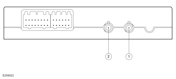

Item Part Number Description
1 — Secondary Cellular Antenna (TCU) Cable Connection
2 — Primary Cellular Antenna Cable Connection

DTC Fault Trigger Conditions

Trouble Code Description Fault Trigger Condition
TCU B1246:11 GSM (Global System for Mobile Communications) Antenna: Short to Ground Stored in continuous memory and during on-demand self-test when the TCU detects a short to ground from the primary cellular antenna cable to the GPS/satellite radio antenna for more than 5 seconds.
TCU B1246:13 GSM (Global System for Mobile Communications) Antenna: Circuit Open Stored in continuous memory and during on-demand self-test when the TCU detects an open in the primary cellular antenna cable to the GPS/satellite radio antenna for more than 5 seconds.

Possible Sources

  • Outdated FordPass Mobile Application software version/level
  • Poor TCU Reception
  • Vehicle Owner's Device
  • Wiring, Terminals or Connectors
  • Cellular Antenna Cable
  • Satellite Radio Antenna Cable
  • Satellite radio antenna
  • TCU

Visual Inspection and Pre-checks

  • Check OASIS for any of the following applicable service articles: TSB, GSB, SSM or FSA. If a service article exists for this concern, stop this test and follow the service article instructions.
  • Ask the vehicle owner the following:
  • Is the FordPass Mobile Application software version level at the latest available software version level?
  • Is the device connected to the FordPass Mobile Application using the login created from the application or the Ford login account of the vehicle owner?
  • Is the vehicle added to the FordPass Mobile Application?
  • Has SYNC Connect been fully activated by authorizing the vehicle in the FordPass Mobile Application?
  • Is the vehicle within range of a cellular tower? Refer to the coverage map on the mobile data service provider website.
  • Check the FordPass Mobile Application for correct operation.
S1 CHECK THE TCU (TELEMATICS CONTROL UNIT) PASSES THE NETWORK TEST
  • The ignition is on.
  • Using the diagnostic scan tool, perform the network test.

Does the TCU pass the network test?
Yes GO to S2
No
REFER TO: Communication Network (418-00 Communication Network, Diagnosis and Testing).
S2 CHECK THE TCU (TELEMATICS CONTROL UNIT) DIAGNOSTIC TROUBLE CODES
  • The ignition is on.
  • Using the diagnostic tool, perform the TCU self-test.

Is any diagnostic trouble code present?
Yes For any GSM antenna DTC, GO to S19.
For all other diagnostic trouble codes (DTCs), REFER to the DTC chart in this section.
No GO to S3
S3 CHECK THE EMBEDDED SERIAL NUMBER
  • The ignition is on.
  • Using the SYNC menu settings, view the embedded modem serial number:
    • Select Settings > General > About SYNC.

Is the embedded modem serial number (ESN) present?
Yes GO to S6
No GO to S4
S4 RESET THE TCU (TELEMATICS CONTROL UNIT) AND RECHECK THE EMBEDDED SERIAL NUMBER
  • Ignition OFF.
  • Remove the TCU fuse.
  • Wait 5 minutes.
  • Install the TCU fuse.
  • The ignition is on.
  • Using the SYNC menu settings, view the embedded modem serial number:
    • Select Settings > General > About SYNC.

Is the embedded modem serial number (ESN) present?
Yes GO to S5
No GO to S21.
S5 CHECK THE SYSTEM OPERATION
  • Start the system and determine whether the concern persists.

Is the concern still present?
Yes GO to S6
No Repair is complete.
S6 CHECK FOR SOFTWARE UPDATE
  • Program the TCU to the latest software version.
    REFER to: Module Programming (418-01 Module Configuration, General Procedures).
  • Check the system and determine whether the concern persists.

Is the concern still present?
Yes GO to S7
No Repair is complete.
S7 CHECK THE TCU (TELEMATICS CONTROL UNIT) CELLULAR SIGNAL STRENGTH STATUS
  • The ignition is on.
  • Using the diagnostic scan tool, access the following TCU PID:
    • Access the TCU and monitor the CELL_SIGNAL PID.

  • NOTE: Drive the vehicle to an area with good cellular coverage. Refer to the coverage map on the mobile data service provider website. Monitor the cellular signal strength.

Is the cellular signal strength between -85 dBm and -95 dBm?
Yes GO to S8
No GO to S19.
S8 CHECK THE TCU (TELEMATICS CONTROL UNIT) AUTHORIZATION STATUS
  • Using the diagnostic scan tool, access the following TCU PID:
    • Access the TCU and monitor the AUTHMODE PID.


Does the display show "Waiting for Authorization" or "Authorized"?
Yes GO to S11
No GO to S9
S9 CHECK IF THE TCU (TELEMATICS CONTROL UNIT) IS IN FACTORY MODE
  • Using the diagnostic scan tool, access the following TCU PID:
    • Access the TCU and monitor the AUTHMODE PID.


Does the display show "Factory Mode"?
Yes GO to S10
No GO to S12
S10 RECHECK IF THE TCU (TELEMATICS CONTROL UNIT) IS IN FACTORY MODE
  • Perform the PMI using the original data.
    REFER to: Module Programming (418-01 Module Configuration, General Procedures).
  • Access the TCU and monitor the AUTHMODE PID.

    • Access the TCU and monitor the AUTHMODE PID.


Does "Factory Mode" still display?
Yes GO to S21.
No GO to S11
S11 RESET THE VEHICLE CONNECTION SETTINGS
  • The ignition is on.
  • Using the vehicle touchscreen, enter the SYNC 3 menu.
    • Select Settings/FordPass Connect/Connection Settings.
  • Turn off the Vehicle Connection option.
  • Ignition OFF.
  • Open, then close the driver door.
  • Lock the vehicle using the button on the ICE or the intelligent access key.
  • Wait 30 seconds.
  • Unlock the vehicle using the button on the ICE or the intelligent access key.
  • The ignition is on.
  • Wait 10 seconds.
  • Using the vehicle touchscreen, enter the SYNC 3 menu.
    • Select Settings/FordPass Connect/Connection Settings.
  • Turn on the Vehicle Connection option.
  • Operate the system and determine if the concern is still present.

Is the concern still present?
Yes GO to S12
No Repair is complete.
S12 CHECK IF THE TCU (TELEMATICS CONTROL UNIT) IS NOT PROVISIONED
  • Using the diagnostic scan tool, access the following TCU PID:
    • Access the TCU and monitor the AUTHMODE PID.


Does the display show "Un-Provisioned"?
Yes GO to S21.
No GO to S13
S13 CHECK THE VEHICLE OPERATION
  • Check that the SYNC Connect function under test operates correctly on the vehicle, independent of the FordPass mobile application. For example, if the SYNC Connect door lock/unlock function does not work, check door lock operation using the door lock control switch and the intelligent access key, remote start function using the intelligent access key, fuel level from the IPC, etc.

Does the function under test operate correctly when checked in the vehicle?
Yes GO to S14
No REFER to the appropriate section in the Workshop Manual to diagnose the non-operating function.
S14 CHECK IF THE TCU (TELEMATICS CONTROL UNIT) IS AUTHORIZED
  • Using the diagnostic scan tool, access the following TCU PID:
    • Access the TCU and monitor the AUTHMODE PID.


Does the display show "Authorized"?
Yes The vehicle is operating correctly. The concern may have been caused by a loss of cellular signal, an outdated FordPass application, or a synchronization issue.
No GO to S15
S15 CHECK IF THE TCU (TELEMATICS CONTROL UNIT) IS WAITING FOR AUTHORIZATION
  • Using the diagnostic scan tool, access the following TCU PID:
    • Access the TCU and monitor the AUTHMODE PID.


Does the display show "Waiting for Authentication"?
Yes GO to S16
No GO to S17.
S16 ADD THE VIN (VEHICLE IDENTIFICATION NUMBER) AND THEN RECHECK IF THE TCU (TELEMATICS CONTROL UNIT) IS AUTHORIZED
  • Add the vehicle VIN to the FordPass/Lincoln Way application, then authorize the vehicle.
  • Access the TCU and monitor the AUTHMODE PID.

    • Access the TCU and monitor the AUTHMODE PID.


Does the display show "Authorized"?
Yes Repair is complete.
No GO to S17.
S17 CHECK FOR LOSS OF COMMUNICATION DIAGNOSTIC TROUBLE CODES (DTCS)
  • Using the diagnostic scan tool, clear all Continuous Monitor Diagnostic Trouble Codes (CMDTCs).
  • Ignition OFF.
  • The ignition is on.
  • Wait at least 10 seconds.
  • Using the diagnostic scan tool, retrieve all Continuous Monitor Diagnostic Trouble Codes (CMDTCs).

Are any loss of communication diagnostic trouble codes (DTCs) set in any audio system module?
Yes REFER to the appropriate DTC chart in this section.
No GO to S18.
S18 PERFORM A SYNC SYSTEM MASTER RESET
  • Perform a master reset from the SYNC Master Reset menu. REFER to the Owner's Literature.
  • Delete the FordPass mobile application from the phone paired with the vehicle.
  • Reinstall the FordPass mobile application on the phone paired with the vehicle.
  • Re-authorize the vehicle from the FordPass application.
  • Operate the system and determine if the concern is still present.

Is the concern still present?
Yes GO to S19.
No Repair is complete.
S19 CHECK THE TCU (TELEMATICS CONTROL UNIT) OUTPUT VOLTAGE AT THE PRIMARY CELLULAR ANTENNA CABLE
  • Ignition OFF.
  • Disconnect the primary cellular antenna cable from the TCU.
  • The ignition is on.
  • NOTE: Refer to the diagram at the beginning of this test to identify the correct TCU cable connection. Using a flexible probe with female thread 300-08058 (0.5 mm x 0.5 mm) or equivalent, measure:
    Positive lead Measurement/Action Negative lead
    Cellular primary antenna cable wire at TCU (component side) Ground

Is the voltage approximately 1.8 volts?
Yes GO to S20
No GO to S21.
S20 CHECK THE VOLTAGE AT THE CELLULAR PRIMARY ANTENNA SPLITTER/COMBINER
  • Ignition OFF.
  • Connect the cellular primary antenna cable to the TCU.
  • Disconnect the cellular primary antenna cable from the cellular primary antenna cable splitter/combiner.
  • The ignition is on.
  • Action:
    Positive lead Measurement/Action Negative lead
    Cellular primary antenna cable wire at cellular primary cable splitter/combiner, cavity 2 Ground

Is the voltage approximately 1.8 volts?
Yes GO to S21.
No INSTALL a new cellular primary antenna cable.
S21 CHECK THE TCU (TELEMATICS CONTROL UNIT) OPERATION
  • Ignition OFF.
  • Inspect the TCU connector.
  • Repair:
    • Corrosion (clean the module terminals or install new connectors or terminals)
    • Damaged or bent terminals (install new terminals or pins)
    • Backed-out pins (install new pins as necessary)
  • Connect the TCU connector. Make sure it is fully seated and latched.
  • Operate the system and determine if the concern is still present.

Is the concern still present?
Yes CHECK OASIS for any applicable service articles: TSB, GSB, SSM or FSA. If a service article exists for this concern, STOP this test and FOLLOW the service article instructions. If no service articles address this concern, INSTALL a new TCU.
REFER TO: Telematics Control Unit (TCU) (415-00 Information and Entertainment System - General Information, Removal and Installation).
No The system is currently operating correctly. The concern may have been caused by module connections. ADDRESS the root cause of any connector or terminal issues.
PINPOINT TEST T: VEHICLE WI-FI HOTSPOT DOES NOT WORK, HAS POOR DATA TRANSFER SPEED, OR CANNOT TRANSMIT ANY DATA

For wiring diagrams and connector information, refer to Cell 130 Wiring Diagrams.

Normal Operation and Fault Symptoms

REFER TO: Information and Entertainment System - Component Location (415-00 Information and Entertainment System - General Information, Description and Operation).
REFER TO: Information and Entertainment System - Overview (415-00 Information and Entertainment System - General Information, Description and Operation).
REFER TO: Information and Entertainment System - System Operation and Component Description (415-00 Information and Entertainment System - General Information, Description and Operation).

TCU Coaxial Cable Connections


Item Part Number Description
1 — Secondary Cellular Antenna (TCU) Cable Connection
2 — Primary Cellular Antenna Cable Connection

DTC Fault Trigger Conditions

Trouble Code Description Fault Trigger Condition
TCU B1D55:11 Antenna No. 2: Short to Ground Stored in continuous memory and during on-demand self-test when the TCU detects a short to ground in the secondary cellular antenna cable for more than 5 seconds.
TCU B1D55:13 Antenna No. 2: Circuit Open Stored in continuous memory and during on-demand self-test when the TCU detects an open in the secondary cellular antenna cable for more than 5 seconds.

Possible Sources

  • FordPass Connect
  • Poor TCU Reception
  • Device connected to the Wi-Fi network
  • Wiring, Terminals or Connectors
  • TCU Antenna
  • Secondary Cellular Antenna Cable (TCU)
  • TCU
T1 CHECK SYNC CONNECT CONNECTION
  • Make sure the SYNC Connect function operates correctly. For example, check operation of the door locks using the SYNC Connect function.

Is the SYNC Connect function working?
Yes GO to T2
No GO to Pinpoint Test S
T2 COMPARE WI-FI SPEED WITH A SECOND DEVICE
  • Park the vehicle away from buildings with a clear view of the sky.
  • Establish a vehicle connection with the Wi-Fi hotspot.
  • Using a laptop (or similar device), connect to the vehicle Wi-Fi hotspot.
    • Using the network connection settings or compatible software on the laptop (or similar device), record the connection speed.
  • Disconnect the laptop (or similar device) from the vehicle Wi-Fi hotspot.
  • Establish a Wi-Fi connection using a mobile phone (or similar device) through the cellular network.
  • Using a laptop (or similar device), connect to the new Wi-Fi hotspot.
    • Using the network connection settings or compatible software on the laptop (or similar device), record the connection speed.
  • Compare the data speed from the vehicle Wi-Fi hotspot with the second device that supports a Wi-Fi hotspot.

Is the vehicle data speed 50% or less than the second device?
Yes GO to T3
No The system is operating as designed. The concern may be caused by environmental conditions or a signal obstruction.
T3 CHECK THE TCU (TELEMATICS CONTROL UNIT) SECONDARY CELLULAR ANTENNA OUTPUT VOLTAGE
  • Ignition OFF.
  • Disconnect the secondary cellular antenna cable from the TCU.
  • The ignition is on.
  • NOTE: Refer to the diagram at the beginning of this test to identify the correct TCU cable connection. Using a flexible probe with female thread 300-08058 (0.5 mm x 0.5 mm) or equivalent, measure:
    Positive lead Measurement/Action Negative lead
    Secondary cellular antenna cable wire at TCU (component side) Ground

Is the voltage approximately 1.8 volts?
Yes GO to T4
No GO to T5
T4 CHECK THE VOLTAGE AT THE TCU (TELEMATICS CONTROL UNIT) ANTENNA
  • Ignition OFF.
  • Connect the secondary cellular antenna cable to the TCU.
  • Disconnect the secondary cellular antenna cable from the TCU antenna.
  • The ignition is on.
  • Action:
    Positive lead Measurement/Action Negative lead
    Secondary cellular (TCU) antenna cable wire at TCU antenna Ground

Is the voltage approximately 1.8 volts?
Yes INSTALL a new secondary cellular (TCU) antenna.
Refer to: Telematics Control Unit (TCU) Antenna (415-00 Information and Entertainment System - General Information, Removal and Installation). CHECK the system for normal operation. If the concern still exists, GO to T5.
No INSTALL a new secondary cellular antenna cable (TCU).
Refer to: Telematics Control Unit (TCU) Antenna Coaxial Cable (415-00 Information and Entertainment System - General Information, Removal and Installation).
T5 CHECK THE TCU (TELEMATICS CONTROL UNIT) OPERATION
  • Ignition OFF.
  • Inspect the TCU connector.
  • Repair:
    • Corrosion (clean the module terminals or install new connectors or terminals)
    • Damaged or bent terminals (install new terminals or pins)
    • Backed-out pins (install new pins as necessary)
  • Connect the TCU connector. Make sure it is fully seated and latched.
  • Operate the system and determine if the concern is still present.

Is the concern still present?
Yes CHECK OASIS for any applicable service articles: TSB, GSB, SSM or FSA. If a service article exists for this concern, STOP this test and FOLLOW the service article instructions. If no service articles address this concern, INSTALL a new TCU.
REFER TO: Telematics Control Unit (TCU) (415-00 Information and Entertainment System - General Information, Removal and Installation).
No The system is currently operating correctly. The concern may have been caused by module connections. ADDRESS the root cause of any connector or terminal issues.
PINPOINT TEST U: APPLINK SYNC PROBLEM

Normal Operation and Fault Symptoms

REFER to: Information and Entertainment System - Overview (415-00 Information and Entertainment System - General Information, Description and Operation).

  • REVIEW the mobile device platform, application and list of compatible application versions. Refer to the applicable authorized Ford website for a list of compatible devices and features. It is normal for incompatible mobile device platforms, applications and application versions to be unavailable through SYNC AppLink.
    • If the mobile device platform, application and application version are compatible and the device is connected via Bluetooth only, GO to Pinpoint Test O.
    • If the mobile device platform, application and application version are compatible and the device is connected via Bluetooth and USB port, GO to Pinpoint Test N.

Possible Sources

  • Refer to Pinpoint Test
Diagnostic steps are not provided for this symptom or diagnostic trouble code. REFER TO: Diagnostic Methods (100-00 General Information, Description and Operation).
PINPOINT TEST V: ANDROID AUTO™ OR APPLE CARPLAY™ PROBLEM

Normal Operation and Fault Symptoms

REFER to: Information and Entertainment System - Overview (415-00 Information and Entertainment System - General Information, Description and Operation).

  • CHECK the USB port operation using a known-good USB device for audio file playback.
    • If the SYNC system does not recognize the USB device, GO to Pinpoint Test N.
    • If the SYNC system recognizes the USB device, refer to the Android Auto™ or Apple CarPlay™ information in the owner's manual.

Possible Sources

  • Refer to Pinpoint Test
PERFORM THE FDRS PROGRAM
  • NOTE: This procedure must be performed using FDRS. Do not clear DTCs until the FDRS procedure is complete.
    To complete the diagnosis, go to the FDRS Step-by-Step Procedure tab and perform the SYNC procedure.

PINPOINT TEST W: U0100:00 (ACM (AUDIO CONTROL MODULE), APIM (APPLICATION PROTOCOL INTERFACE MODULE), TCU (TELEMATICS CONTROL UNIT))

Normal Operation and Fault Symptoms

The ACM, APIM and TCU communicate with the PCM over the CAN bus. If messages are missing or not received from the PCM module, functions such as speed-compensated volume may not operate.

DTC Fault Trigger Conditions

Trouble Code Description Fault Trigger Condition
ACM U0100:00 Lost Communication with ECM/PCM 'A': No Sub Type Information Stored in continuous memory when the ACM detects that network messages are missing from the PCM for more than 5 seconds.
APIM U0100:00 Lost Communication with ECM/PCM 'A': No Sub Type Information Stored in continuous memory when the APIM detects that network messages are missing from the PCM for more than 5 seconds.
TCU U0100:00 Lost Communication with ECM/PCM 'A': No Sub Type Information Stored in continuous memory when the TCU detects that network messages are missing from the PCM for more than 5 seconds.

Possible Sources

  • Network communication fault
  • ACM
  • APIM
  • TCU
  • PCM
W1 CONFIRM THE CONCERN
  • The ignition is on.
  • Make sure the observed symptom is present.

Is the observed symptom present?
Yes GO to W2
No The system is currently operating normally. The DTC may have been set due to high network traffic or an intermittent fault.
W2 CHECK THE COMMUNICATION NETWORK
  • Using the diagnostic scan tool, perform the network test.

Does the PCM pass the network test?
Yes GO to W3
No
REFER TO: Communication Network (418-00 Communication Network, Diagnosis and Testing).
W3 CHECK FOR NON-NETWORK DIAGNOSTIC TROUBLE CODES (DTCS)
  • Using the diagnostic scan tool, perform a self-test of the applicable module (ACM, APIM, TCU) by setting the DTC.

Are there any non-network diagnostic trouble codes (DTCs)?
Yes First CHECK all non-network diagnostic trouble codes (DTCs). Refer to the DTC Chart in this section.
No GO to W4
W4 CHECK THE PCM (POWERTRAIN CONTROL MODULE) DIAGNOSTIC TROUBLE CODES (DTCS)
  • Using the diagnostic scan tool, perform a PCM self-test.

Are there any non-network diagnostic trouble codes (DTCs)?
Yes Refer to Diagnosis and Testing in the appropriate section 303-14.
No GO to W5
W5 RECHECK FOR DTC U0100:00
  • Using the diagnostic scan tool, clear the diagnostic trouble codes (DTCs) for the module in question (ACM, APIM, TCU). Set the DTC.
  • Ignition OFF.
  • The ignition is on.
  • Wait 10 seconds.
  • Using the diagnostic scan tool, perform a self-test of the applicable module (ACM, APIM, TCU) by setting the DTC.

Is DTC U0100:00 still present?
Yes GO to W6
No The system is currently operating correctly. The DTC may have been set due to high network traffic or an intermittent fault.
W6 CHECK FOR OTHER CAUSES OF NETWORK COMMUNICATION CONCERNS
  • Review the vehicle service history for recent service actions related to the PCM and the applicable module (ACM, APIM, TCU) that set the DTC. If recent service history is found:
    • make sure the correct replacement module was installed
      • Use the vehicle parts list to verify that parts were installed correctly.
    • make sure the replacement module configuration was correct
      • reconfigure the module using the original data if the previous configuration is suspected
    • Make sure the module was not obtained from a similar vehicle and was not installed in the vehicle in error.
      • Reinstall the replaced module in the original vehicle and obtain a new replacement module.
  • Operate the system and determine whether the observed symptom persists.

Is the observed symptom still present?
Yes GO to W7
No The system is currently operating correctly. The concern may have been caused by incorrect part replacement procedures or incorrect module configuration.
W7 CHECK PCM (POWERTRAIN CONTROL MODULE) OPERATION
  • Ignition OFF.
  • Disconnect and inspect all PCM connectors.
  • Repair:
    • corrosion (install new connectors or terminals - clean the module contacts)
    • damaged or bent pins - install new terminal pins
    • pushed-out pins - install new pins as necessary
  • Connect the PCM connectors. Make sure they are fully seated and locked.
  • Operate the system and determine if the concern is still present.

Is the concern still present?
Yes CHECK OASIS for any applicable service articles: TSB, GSB, SSM or FSA. If a service article exists for this concern, STOP this test and FOLLOW the service article instructions. If there are no service articles to resolve this concern,
VIN required to access Guided Routine (PCM)
No The system is currently operating correctly. The concern may have been caused by module connections. ADDRESS the root cause of any connector or terminal issues.
PINPOINT TEST X: U0121:00 (ACM (AUDIO CONTROL MODULE))

Normal Operation and Fault Symptoms

The ACM communicates with the ABS module over the CAN bus. If messages are missing or not received from the ABS module, the GPS function may not be accurate.

DTC Fault Trigger Conditions

Trouble Code Description Fault Trigger Condition
ACM U0121:00 Lost Communication with Anti-Lock Brake System (ABS) Control Module 'A': No Sub-type Information Stored in continuous memory when the ACM detects a lack of network messages from the ABS module for more than 5 seconds.

Possible Sources

  • Network communication fault
  • ACM
  • ABS Module
X1 CONFIRM THE CONCERN
  • The ignition is on.
  • Make sure the observed symptom is present.

Is the observed symptom present?
Yes GO to X2
No CLEAR the DTC. The system is currently operating correctly. The DTC may have been set due to high network traffic or an intermittent fault condition.
X2 CHECK THE COMMUNICATION NETWORK
  • Using the diagnostic scan tool, perform the network test.

Does the ABS module pass the network test?
Yes GO to X3
No
REFER TO: Communication Network (418-00 Communication Network, Diagnosis and Testing).
X3 CHECK FOR NON-NETWORK DIAGNOSTIC TROUBLE CODES (DTCS)
  • Using the diagnostic scan tool, perform the ACM self-test.

Are there any non-network diagnostic trouble codes (DTCs)?
Yes First CHECK all non-network diagnostic trouble codes (DTCs). Refer to the DTC Chart in this section.
No GO to X4
X4 CHECK THE ABS (ANTI-LOCK BRAKE SYSTEM) MODULE NON-NETWORK DIAGNOSTIC TROUBLE CODES (DTCS)
  • Using the diagnostic scan tool, perform a self-test of the ABS module.

Are there any non-network diagnostic trouble codes (DTCs)?
Yes
REFER TO: Anti-Lock Brake System (ABS) and Stability Control System (206-09 Anti-Lock Brake System (ABS) and Stability Control System, Diagnosis and Testing).
No GO to X5
X5 RECHECK FOR DTC U0121:00
  • Using the diagnostic scan tool, clear the diagnostic trouble codes (DTCs) for the ACM.
  • Ignition OFF.
  • The ignition is on.
  • Wait 10 seconds.
  • Using the diagnostic scan tool, perform the ACM self-test.

Is DTC U0121:00 still present?
Yes GO to X6
No The system is currently operating correctly. The DTC may have been set due to high network traffic or an intermittent fault.
X6 CHECK FOR OTHER CAUSES OF NETWORK COMMUNICATION CONCERNS
  • Review the vehicle service history for recent service actions related to the ABS module and ACM. If recent service history is found:
    • make sure the correct replacement module was installed
      • Use the vehicle parts list to verify that parts were installed correctly.
    • make sure the replacement module configuration was correct
      • reconfigure the module using the original data if the previous configuration is suspected
    • Make sure the module was not obtained from a similar vehicle and was not installed in the vehicle in error.
      • Reinstall the replaced module in the original vehicle and obtain a new replacement module.
  • Operate the system and determine whether the observed symptom persists.

Is the observed symptom still present?
Yes GO to X7
No The system is currently operating correctly. The concern may have been caused by incorrect part replacement procedures or incorrect module configuration.
X7 CHECK THE ABS (ANTI-LOCK BRAKE SYSTEM) MODULE FOR PROPER OPERATION
  • Ignition OFF.
  • Disconnect and inspect the ABS module connector.
  • Repair:
    • corrosion (install new connectors or terminals - clean the module contacts)
    • damaged or bent pins - install new terminal pins
    • pushed-out pins - install new pins as necessary
  • Reconnect the ABS module connector. Make sure it is properly seated and latched.
  • Operate the system and determine if the concern is still present.

Is the concern still present?
Yes CHECK in OASIS for any applicable service articles: TSB, GSB, SSM or FSA. If a service article exists for this concern, STOP this test and FOLLOW the service article instructions. If no service articles address this concern, INSTALL a new ABS module. REFER to the appropriate Removal and Installation procedure in Section 206-09.
No The system is currently operating correctly. The concern may have been caused by module connections. ADDRESS the root cause of any connector or terminal issues.
PINPOINT TEST Y: U0140:00 (ACM (AUDIO CONTROL MODULE), DSP (DIGITAL SIGNAL PROCESSOR), TCU (TELEMATICS CONTROL UNIT))

Normal Operation and Fault Symptoms

The ACM, DSP and TCU exchange data with the BCM over the CAN bus. If messages are missing or not received from the BCM, the display screen brightness may not function properly.

DTC Fault Trigger Conditions

Trouble Code Description Fault Trigger Condition
ACM U0140:00 Lost Communication With Body Control Module: No Sub Type Information Stored in continuous memory when the ACM detects that network messages are missing from the BCM for more than 5 seconds.
DSP U0140:00 Lost Communication With Body Control Module: No Sub Type Information Stored in continuous memory when the DSP detects that network messages are missing from the BCM for more than 5 seconds.
TCU U0140:00 Lost Communication With Body Control Module: No Sub Type Information Stored in continuous memory when the TCU detects that network messages are missing from the BCM for more than 5 seconds.

Possible Sources

  • Network communication fault
  • ACM
  • DSP
  • TCU
  • BCM
Y1 CONFIRM THE CONCERN
  • The ignition is on.
  • Make sure the observed symptom is present.

Is the observed symptom present?
Yes GO to Y2
No CLEAR the DTC. The system is currently operating correctly. The DTC may have been set due to high network traffic or an intermittent fault condition.
Y2 CHECK NETWORK COMMUNICATION
  • Using the diagnostic scan tool, perform the network test.

Does the BCM pass the network test?
Yes GO to Y3
No
REFER TO: Communication Network (418-00 Communication Network, Diagnosis and Testing).
Y3 CHECK FOR NON-NETWORK DIAGNOSTIC TROUBLE CODES (DTCS)
  • Using the diagnostic scan tool, perform a self-test of the applicable module (ACM, DSP, TCU) by setting the DTC.

Are there any non-network diagnostic trouble codes (DTCs)?
Yes First CHECK all non-network diagnostic trouble codes (DTCs). Refer to the DTC Chart in this section.
No GO to Y4
Y4 CHECK THE BCM (BODY CONTROL MODULE) NON-NETWORK DIAGNOSTIC TROUBLE CODES (DTCS)
  • Using a scan tool, perform the BCM self-test.

Are there any non-network diagnostic trouble codes (DTCs)?
Yes
REFER TO: Body Control Module (BCM) (419-10 Multifunction Electronic Modules, Diagnosis and Testing).
No GO to Y5
Y5 RECHECK FOR DTC U0140:00
  • Using the diagnostic scan tool, clear the diagnostic trouble codes (DTCs) for the module in question (ACM, DSP, TCU). Set the DTC.
  • Ignition OFF.
  • The ignition is on.
  • Wait 10 seconds.
  • Using the diagnostic scan tool, perform a self-test of the applicable module (ACM, DSP, TCU) by setting the DTC.

Is DTC U0140:00 still present?
Yes GO to Y6
No The system is currently operating correctly. The DTC may have been set due to high network traffic or an intermittent fault.
Y6 CHECK FOR OTHER CAUSES OF NETWORK COMMUNICATION PROBLEMS
  • Review the vehicle service history for recent service actions related to the BCM and the module in question (ACM, DSP, TCU) that set the DTC. If recent service history is found:
    • make sure the correct replacement module was installed
      • Use the vehicle parts list to verify that parts were installed correctly.
    • make sure the replacement module configuration was correct
      • reconfigure the module using the original data if the previous configuration is suspected
    • Make sure the module was not obtained from a similar vehicle and was not installed in the vehicle in error.
      • Reinstall the replaced module in the original vehicle and obtain a new replacement module.
  • Operate the system and determine whether the observed symptom persists.

Is the observed symptom still present?
Yes GO to Y7
No The system is currently operating correctly. The concern may have been caused by incorrect part replacement procedures or incorrect module configuration.
Y7 CHECK THE BCM (BODY CONTROL MODULE) FOR PROPER OPERATION
  • Ignition OFF.
  • Disconnect and inspect the BCM connectors.
  • Repair:
    • corrosion (install new connectors or terminals - clean the module contacts)
    • damaged or bent pins - install new terminal pins
    • pushed-out pins - install new pins as necessary
  • Reconnect the BCM connectors. Make sure they are fully seated and locked.
  • Operate the system and determine if the concern is still present.

Is the concern still present?
Yes CHECK in OASIS for any applicable service articles: TSB, GSB, SSM or FSA. If a service article exists for this concern, STOP this test and FOLLOW the service article instructions. If no service articles address this concern, INSTALL a new BCM.
REFER TO: Body Control Module (BCM) (419-10 Multifunction Electronic Modules, Diagnosis and Testing).
No The system is currently operating correctly. The concern may have been caused by module connections. ADDRESS the root cause of any connector or terminal issues.
PINPOINT TEST Z: U0155:00 (ACM (AUDIO CONTROL MODULE), DSP (DIGITAL SIGNAL PROCESSOR))

Normal Operation and Fault Symptoms

The ACM and DSP exchange data with the IPC over the CAN bus. If messages are missing or not received from the IPC, functions such as display backlighting or warning chimes may not function properly.

DTC Fault Trigger Conditions

Trouble Code Description Fault Trigger Condition
ACM U0155:00 Lost Communication with Instrument Panel Cluster (IPC) Control Module: No Sub Type Information Stored in continuous memory when the ACM detects a lack of network messages from the IPC for more than 5 seconds.
DSP U0155:00 Lost Communication with Instrument Panel Cluster (IPC) Control Module: No Sub Type Information Stored in continuous memory when the DSP detects that network messages are missing from the IPC for more than 5 seconds.

Possible Sources

  • Network communication fault
  • ACM
  • DSP
  • PCM
Z1 CONFIRM THE CONCERN
  • The ignition is on.
  • Make sure the observed symptom is present.

Is the observed symptom present?
Yes GO to Z2
No CLEAR the DTC. The system is currently operating correctly. The DTC may have been set due to high network traffic or an intermittent fault condition.
Z2 CHECK THE COMMUNICATION NETWORK
  • Using the diagnostic scan tool, perform the network test.

Does the IPC pass the network test?
Yes GO to Z3
No
REFER TO: Communication Network (418-00 Communication Network, Diagnosis and Testing).
Z3 CHECK FOR NON-NETWORK DIAGNOSTIC TROUBLE CODES (DTCS)
  • Using the diagnostic scan tool, perform a self-test of the applicable module (ACM, DSP) by setting the DTC.

Are there any non-network diagnostic trouble codes (DTCs)?
Yes First CHECK all non-network diagnostic trouble codes (DTCs). Refer to the DTC Chart in this section.
No GO to Z4
Z4 CHECK THE IPC (INSTRUMENT PANEL CLUSTER) NON-NETWORK DIAGNOSTIC TROUBLE CODES (DTCS)
  • Using the diagnostic scan tool, perform the IPC self-test.

Are there any non-network diagnostic trouble codes (DTCs)?
Yes
REFER TO: Instrument Cluster, Message Center and Warning Chimes - Vehicles With: Head-Up Display (HUD) (413-01 Instrument Cluster, Message Center and Warning Chimes, Diagnosis and Testing).
No GO to Z5
Z5 RECHECK FOR DTC U0155:00
  • Using the diagnostic scan tool, clear the diagnostic trouble codes (DTCs) for the module in question (ACM, DSP). Set the DTC.
  • Ignition OFF.
  • The ignition is on.
  • Wait 10 seconds.
  • Using the diagnostic scan tool, perform a self-test of the applicable module (ACM, DSP) by setting the DTC.

Is DTC U0155:00 still present?
Yes GO to Z6
No The system is currently operating correctly. The DTC may have been set due to high network traffic or an intermittent fault.
Z6 CHECK FOR OTHER CAUSES OF NETWORK COMMUNICATION PROBLEMS
  • Review the vehicle service history for recent service actions related to the IPC and the module in question (ACM, DSP) that set the DTC. If recent service history is found:
    • make sure the correct replacement module was installed
      • Use the vehicle parts list to verify that parts were installed correctly.
    • make sure the replacement module configuration was correct
      • reconfigure the module using the original data if the previous configuration is suspected
    • Make sure the module was not obtained from a similar vehicle and was not installed in the vehicle in error.
      • Reinstall the replaced module in the original vehicle and obtain a new replacement module.
  • Operate the system and determine whether the observed symptom persists.

Is the observed symptom still present?
Yes GO to Z7
No The system is currently operating correctly. The concern may have been caused by incorrect part replacement procedures or incorrect module configuration.
Z7 CHECK THE IPC (INSTRUMENT PANEL CLUSTER) FOR PROPER OPERATION
  • Ignition OFF.
  • Disconnect and inspect the IPC connector.
  • Repair:
    • corrosion (install new connectors or terminals - clean the module contacts)
    • damaged or bent pins - install new terminal pins
    • pushed-out pins - install new pins as necessary
  • Reconnect the IPC connector. Make sure it is properly seated and latched.
  • Operate the system and determine if the concern is still present.

Is the concern still present?
Yes CHECK OASIS for any applicable service articles: TSB, GSB, SSM or FSA. If a service article exists for this concern, STOP this test and FOLLOW the service article instructions. If no service articles address this concern, INSTALL a new IPC. Refer to the appropriate removal and installation procedure in Section 413-01.
No The system is currently operating correctly. The concern may have been caused by module connections. ADDRESS the root cause of any connector or terminal issues.
PINPOINT TEST AA: U0184:00 (DSP (DIGITAL SIGNAL PROCESSOR))

Normal Operation and Fault Symptoms

The DSP communicates with the ACM over the CAN bus. If messages are missing or not received from the ACM, the touchscreen display is blank.

DTC Fault Trigger Conditions

Trouble Code Description Fault Trigger Condition
DSP U0184:00 Lost Communication With Radio: No Sub Type Information Stored in continuous memory when the DSP detects that network messages are missing from the ACM for more than 5 seconds.

Possible Sources

  • Network communication fault
  • DSP
  • ACM
AA1 CONFIRM THE CONCERN
  • The ignition is on.
  • Make sure the observed symptom is present.

Is the observed symptom present?
Yes GO to AA2
No CLEAR the DTC. The system is currently operating correctly. The DTC may have been set due to high network traffic or an intermittent fault condition.
AA2 CHECK NETWORK COMMUNICATION
  • Using the diagnostic scan tool, perform the network test.

Does the ACM pass the network test?
Yes GO to AA3
No
REFER TO: Communication Network (418-00 Communication Network, Diagnosis and Testing).
AA3 CHECK FOR NON-NETWORK DIAGNOSTIC TROUBLE CODES (DTCS)
  • Using the diagnostic scan tool, perform the DSP self-test.

Are there any non-network diagnostic trouble codes (DTCs)?
Yes First CHECK all non-network diagnostic trouble codes (DTCs). Refer to the DTC Chart in this section.
No GO to AA4
AA4 CHECK THE NON-NETWORK ACM (FRONT AUDIO CONTROL MODULE) DIAGNOSTIC TROUBLE CODES (DTCS)
  • Using the diagnostic scan tool, perform the ACM self-test.

Are there any non-network diagnostic trouble codes (DTCs)?
Yes First CHECK all non-network diagnostic trouble codes (DTCs). Refer to the DTC Chart in this section.
No GO to AA5
AA5 RECHECK FOR DTC U0184:00
  • Using the diagnostic scan tool, clear the diagnostic trouble codes (DTCs) for the DSP.
  • Ignition OFF.
  • The ignition is on.
  • Wait 10 seconds.
  • Using the diagnostic scan tool, perform the DSP self-test.

IS DTC U0184:00 STILL PRESENT?
Yes GO to AA6
No The system is currently operating correctly. The DTC may have been set due to high network traffic or an intermittent fault.
AA6 CHECK FOR OTHER CAUSES OF NETWORK COMMUNICATION CONCERNS
  • Review the vehicle service history for recent service actions related to the ACM and DSP. If recent service history is found:
    • make sure the correct replacement module was installed
      • Use the vehicle parts list to verify that parts were installed correctly.
    • make sure the replacement module configuration was correct
      • reconfigure the module using the original data if the previous configuration is suspected
    • Make sure the module was not obtained from a similar vehicle and was not installed in the vehicle in error.
      • Reinstall the replaced module in the original vehicle and obtain a new replacement module.
  • Operate the system and determine whether the observed symptom persists.

Is the observed symptom still present?
Yes GO to AA7.
No The system is currently operating correctly. The concern may have been caused by incorrect part replacement procedures or incorrect module configuration.
AA7 CHECK ACM (FRONT AUDIO CONTROL MODULE) OPERATION
  • Ignition OFF.
  • Disconnect and inspect the ACM connectors.
  • Repair:
    • corrosion (install new connectors or terminals - clean the module contacts)
    • damaged or bent pins - install new terminal pins
    • pushed-out pins - install new pins as necessary
  • Connect the ACM connectors. Make sure they are fully seated and locked.
  • Operate the system and determine if the concern is still present.

Is the concern still present?
Yes CHECK OASIS for any applicable service articles: TSB, GSB, SSM or FSA. If a service article exists for this concern, DISCONTINUE this test and FOLLOW the service article instructions. If no service article resolves this concern, INSTALL a new ACM.
REFER TO: Front Audio Control Module (ACM) (415-00 Infotainment System - General Information, Removal and Installation).
No The system is currently operating correctly. The concern may have been caused by module connections. ADDRESS the root cause of any connector or terminal issues.
PINPOINT TEST AB: U0198:00 (DSP (DIGITAL SIGNAL PROCESSOR))

Normal Operation and Fault Symptoms

The DSP communicates with the TCU over the CAN bus. If messages are missing or not received from the TCU, the SYNC Connect function may not operate correctly.

DTC Fault Trigger Conditions

Trouble Code Description Fault Trigger Condition
DSP U0198:00 Lost Communication with Telematic Control Module A: No Sub-type Information Stored in continuous memory when the DSP detects that network messages from the TCU have been missing for more than 5 seconds.

Possible Sources

  • Network communication fault
  • DSP
  • TCU
AB1 CONFIRM THE CONCERN
  • The ignition is on.
  • Make sure the observed symptom is present.

Is the observed symptom present?
Yes GO to AB2
No CLEAR the DTC. The system is currently operating correctly. The DTC may have been set due to high network traffic or an intermittent fault condition.
AB2 CHECK NETWORK COMMUNICATION
  • Using the diagnostic scan tool, perform the network test.

Does the TCU pass the network test?
Yes GO to AB3
No
REFER TO: Communication Network (418-00 Communication Network, Diagnosis and Testing).
AB3 CHECK FOR NON-NETWORK DIAGNOSTIC TROUBLE CODES (DTCS)
  • Using the diagnostic scan tool, perform the DSP self-test.

Are there any non-network diagnostic trouble codes (DTCs)?
Yes First CHECK all non-network diagnostic trouble codes (DTCs). Refer to the DTC Chart in this section.
No GO to AB4
AB4 CHECK NON-NETWORK TCU (TELEMATIC CONTROL UNIT) DIAGNOSTIC TROUBLE CODES (DTCS)
  • Using the scan tool, perform the TCU self-test.

Are there any non-network diagnostic trouble codes (DTCs)?
Yes First CHECK all non-network diagnostic trouble codes (DTCs). Refer to the DTC Chart in this section.
No GO to AB5
AB5 RECHECK DTC (DIAGNOSTIC TROUBLE CODE) U0198:00
  • Using the diagnostic scan tool, clear the diagnostic trouble codes (DTCs) for the DSP.
  • Ignition OFF.
  • The ignition is on.
  • Wait 10 seconds.
  • Using the diagnostic scan tool, perform the DSP self-test.

IS DTC U0198:00 STILL PRESENT?
Yes GO to AB6
No The system is currently operating correctly. The DTC may have been set due to high network traffic or an intermittent fault.
AB6 CHECK FOR OTHER CAUSES OF NETWORK COMMUNICATION PROBLEMS
  • Check the vehicle service history for recent service actions related to the TCU and DSP. If recent service history is found:
    • make sure the correct replacement module was installed
      • Use the vehicle parts list to verify that parts were installed correctly.
    • make sure the replacement module configuration was correct
      • reconfigure the module using the original data if the previous configuration is suspected
    • Make sure the module was not obtained from a similar vehicle and was not installed in the vehicle in error.
      • Reinstall the replaced module in the original vehicle and obtain a new replacement module.
  • Operate the system and determine whether the observed symptom persists.

Is the observed symptom still present?
Yes GO to AB7
No The system is currently operating correctly. The concern may have been caused by incorrect part replacement procedures or incorrect module configuration.
AB7 CHECK TCU (TELEMATIC CONTROL UNIT) OPERATION
  • Ignition OFF.
  • Disconnect and inspect the TCU connectors.
  • Repair:
    • corrosion (install new connectors or terminals - clean the module contacts)
    • damaged or bent pins - install new terminal pins
    • pushed-out pins - install new pins as necessary
  • Connect the TCU connectors. Make sure they are fully seated and locked.
  • Operate the system and determine if the concern is still present.

Is the concern still present?
Yes CHECK OASIS for any applicable service articles: TSB, GSB, SSM or FSA. If a service article exists for this concern, STOP this test and FOLLOW the service article instructions. If no service articles address this concern, INSTALL a new TCU.
REFER TO: Telematics Control Unit (TCU) (415-00 Information and Entertainment System - General Information, Removal and Installation).
No The system is currently operating correctly. The concern may have been caused by module connections. ADDRESS the root cause of any connector or terminal issues.
PINPOINT TEST AC: U0238:00 (ACM (AUDIO CONTROL MODULE))

Normal Operation and Fault Symptoms

The ACM communicates with the DSP audio module over the CAN bus. If messages are missing or not received from the DSP, functions such as ANK may operate incorrectly.

DTC Fault Trigger Conditions

Trouble Code Description Fault Trigger Condition
ACM U0238:00 Lost communication with Digital Sound Processor module "D": no sub-type information Stored in continuous memory when the ACM detects that network messages from the DSP have been missing for more than 5 seconds.

Possible Sources

  • Network communication fault
  • ACM
  • DSP
AC1 CONFIRM THE CONCERN
  • The ignition is on.
  • Make sure the observed symptom is present.

Is the observed symptom present?
Yes GO to AC2
No CLEAR the DTC. The system is currently operating correctly. The DTC may have been set due to high network traffic or an intermittent fault condition.
AC2 CHECK THE NETWORK COMMUNICATION
  • Using the diagnostic scan tool, perform the network test.

Does the DSP pass the network test?
Yes GO to AC3
No
REFER TO: Communication Network (418-00 Communication Network, Diagnosis and Testing).
AC3 CHECK FOR NON-NETWORK DIAGNOSTIC TROUBLE CODES (DTCS)
  • Using the diagnostic scan tool, perform the ACM self-test.

Are there any non-network diagnostic trouble codes (DTCs)?
Yes First CHECK all non-network diagnostic trouble codes (DTCs). Refer to the DTC Chart in this section.
No GO to AC4
AC4 CHECK NON-NETWORK DSP (DIGITAL SOUND PROCESSOR) DIAGNOSTIC TROUBLE CODES (DTCS)
  • Using the diagnostic scan tool, perform the DSP self-test.

Are there any non-network diagnostic trouble codes (DTCs)?
Yes First CHECK all non-network diagnostic trouble codes (DTCs). Refer to the DTC Chart in this section.
No GO to AC5
AC5 RECHECK DTC (DIAGNOSTIC TROUBLE CODE) U0238:00
  • Using the diagnostic scan tool, clear the diagnostic trouble codes (DTCs) for the ACM.
  • Ignition OFF.
  • The ignition is on.
  • Wait 10 seconds.
  • Using the diagnostic scan tool, perform the ACM self-test.

IS DTC U0238:00 STILL PRESENT?
Yes GO to AC6
No The system is currently operating correctly. The DTC may have been set due to high network traffic or an intermittent fault.
AC6 CHECK FOR OTHER CAUSES OF NETWORK COMMUNICATION PROBLEMS
  • Check the vehicle service history for recent service actions related to the DSP audio module and ACM. If recent service history is found:
    • make sure the correct replacement module was installed
      • Use the vehicle parts list to verify that parts were installed correctly.
    • make sure the replacement module configuration was correct
      • reconfigure the module using the original data if the previous configuration is suspected
    • Make sure the module was not obtained from a similar vehicle and was not installed in the vehicle in error.
      • Reinstall the replaced module in the original vehicle and obtain a new replacement module.
  • Operate the system and determine whether the observed symptom persists.

Is the observed symptom still present?
Yes GO to AC7
No The system is currently operating correctly. The concern may have been caused by incorrect part replacement procedures or incorrect module configuration.
AC7 CHECK DSP (DIGITAL SOUND PROCESSOR) OPERATION
  • Ignition OFF.
  • Disconnect and inspect the DSP connectors.
  • Repair:
    • corrosion (install new connectors or terminals - clean the module contacts)
    • damaged or bent pins - install new terminal pins
    • pushed-out pins - install new pins as necessary
  • Reconnect the DSP connectors. Make sure they are fully seated and locked.
  • Operate the system and determine if the concern is still present.

Is the concern still present?
Yes CHECK OASIS for any applicable service articles: TSB, GSB, SSM or FSA. If a service article exists for this concern, STOP this test and FOLLOW the service article instructions. If no service articles address this concern, INSTALL a new DSP.
REFER TO: Digital Sound Processor (DSP) (415-00 Information and Entertainment System, Removal and Installation).
No The system is currently operating correctly. The concern may have been caused by module connections. ADDRESS the root cause of any connector or terminal issues.
PINPOINT TEST AD: U0253:00 (ACM (AUDIO CONTROL MODULE), DSP (DIGITAL SIGNAL PROCESSOR), TCU (TELEMATICS CONTROL UNIT))

Normal Operation and Fault Symptoms

The ACM, DSP and TCU exchange data with the APIM over CAN. If messages are missing or not received from the APIM, the display is blank.

DTC Fault Trigger Conditions

Trouble Code Description Fault Trigger Condition
ACM U0253:00 Lost Communication with Auxiliary Protocol Interface Module: No Sub Type Information Stored in continuous memory when the ACM detects that network messages from the APIM have been missing for more than 5 seconds.
DSP U0253:00 Lost Communication with Auxiliary Protocol Interface Module: No Sub Type Information Stored in continuous memory when the DSP detects that network messages from the APIM have been missing for more than 5 seconds.
TCU U0253:00 Lost Communication with Auxiliary Protocol Interface Module: No Sub Type Information Stored in continuous memory when the TCU detects that network messages from the APIM have been missing for more than 5 seconds.

Possible Sources

  • Network communication fault
  • ACM
  • DSP
  • TCU
  • APIM
AD1 CONFIRM THE CONCERN
  • The ignition is on.
  • Make sure the observed symptom is present.

Is the observed symptom present?
Yes GO to AD2
No CLEAR the DTC. The system is currently operating correctly. The DTC may have been set due to high network traffic or an intermittent fault condition.
AD2 CHECK NETWORK COMMUNICATION
  • Using the diagnostic scan tool, perform the network test.

Does the APIM pass the network test?
Yes GO to AD3
No
REFER TO: Communication Network (418-00 Communication Network, Diagnosis and Testing).
AD3 CHECK NON-NETWORK DIAGNOSTIC TROUBLE CODES (DTCS)
  • Using the diagnostic scan tool, perform a self-test of the applicable module (ACM, DSP, TCU) by setting the DTC.

Are there any non-network diagnostic trouble codes (DTCs)?
Yes First CHECK all non-network diagnostic trouble codes (DTCs). Refer to the DTC Chart in this section.
No GO to AD4
AD4 CHECK NON-NETWORK APIM (SYNC MODULE) DIAGNOSTIC TROUBLE CODES (DTCS)
  • Using the diagnostic scan tool, perform the APIM self-test.

Are there any non-network diagnostic trouble codes (DTCs)?
Yes First CHECK all non-network diagnostic trouble codes (DTCs). Refer to the DTC Chart in this section.
No GO to AD5
AD5 RECHECK DTC (DIAGNOSTIC TROUBLE CODE) U0253:00
  • Using the diagnostic scan tool, clear the diagnostic trouble codes (DTCs) for the module in question (ACM, DSP, TCU). Set the DTC.
  • Ignition OFF.
  • The ignition is on.
  • Wait 10 seconds.
  • Using the diagnostic scan tool, perform a self-test of the applicable module (ACM, DSP, TCU) by setting the DTC.

Is DTC U0253:00 still present?
Yes GO to AD6
No The system is currently operating correctly. The DTC may have been set due to high network traffic or an intermittent fault.
AD6 CHECK OTHER CAUSES OF NETWORK COMMUNICATION CONCERNS
  • Check the vehicle service history for recent service actions related to the APIM and the module in question (ACM, DSP, TCU) that set the DTC. If recent service history is found:
    • make sure the correct replacement module was installed
      • Use the vehicle parts list to verify that parts were installed correctly.
    • make sure the replacement module configuration was correct
      • reconfigure the module using the original data if the previous configuration is suspected
    • Make sure the module was not obtained from a similar vehicle and was not installed in the vehicle in error.
      • Reinstall the replaced module in the original vehicle and obtain a new replacement module.
  • Operate the system and determine whether the observed symptom persists.

Is the observed symptom still present?
Yes GO to AD7
No The system is currently operating correctly. The concern may have been caused by incorrect part replacement procedures or incorrect module configuration.
AD7 CHECK APIM (SYNC MODULE) OPERATION
  • Ignition OFF.
  • Disconnect and inspect the APIM connectors.
  • Repair:
    • corrosion (install new connectors or terminals - clean the module contacts)
    • damaged or bent pins - install new terminal pins
    • pushed-out pins - install new pins as necessary
  • Reconnect the APIM connectors. Make sure they are fully seated and locked.
  • Operate the system and determine if the concern is still present.

Is the concern still present?
Yes CHECK OASIS for any applicable service articles: TSB, GSB, SSM or FSA. If a service article exists for this concern, DISCONTINUE this test and FOLLOW the service article instructions. If no service article resolves this concern, GO to Pinpoint Test AN.
No The system is currently operating correctly. The concern may have been caused by module connections. ADDRESS the root cause of any connector or terminal issues.
PINPOINT TEST AE: U3003:16 (ACM (AUDIO CONTROL MODULE), APIM (APPLICATION PROTOCOL INTERFACE MODULE), DSP (DIGITAL SIGNAL PROCESSOR), TCU (TELEMATICS CONTROL UNIT))

For wiring diagrams and connector information, refer to Cell 130 Wiring Diagrams.

Normal Operation and Fault Symptoms

Modules monitor the supply voltage and set a DTC if it falls below a threshold value.

DTC Fault Trigger Conditions

Trouble Code Description Fault Trigger Condition
ACM U3003:16 Battery Voltage: Circuit Voltage Below Threshold Stored in continuous memory and during on-demand self-test when the ACM detects a supply voltage below 10 volts.
APIM U3003:16 Battery Voltage: Circuit Voltage Below Threshold Stored in continuous memory and during on-demand self-test when the APIM detects a supply voltage below 10 volts.
DSP U3003:16 Battery Voltage: Circuit Voltage Below Threshold Stored in continuous memory and during on-demand self-test when the DSP detects a supply voltage below 10 volts.
TCU U3003:16 Battery Voltage: Circuit Voltage Below Threshold Stored in continuous memory and during on-demand self-test when the TCU detects a supply voltage below 10 volts.

Possible Sources

  • Previous Low Battery Voltage
  • Wiring, Terminals or Connectors
  • Charging System Concern
  • ACM
  • APIM
  • DSP
  • TCU
RECHECK AE1 FOR LOW VOLTAGE DIAGNOSTIC TROUBLE CODES (DTCS)
  • The ignition is on.
  • Using the scan tool, clear the diagnostic trouble codes (DTCs) from the applicable module that set the low voltage DTC.
  • Wait 10 seconds.
  • Using the scan tool, perform a self-test of the applicable module that set the low voltage DTC.

IS DTC U3003:16 STILL PRESENT?
Yes GO to AE2
No The system is currently operating correctly. The DTC may have been set due to a previous low battery voltage condition.
AE2 CHECK CHARGING SYSTEM DIAGNOSTIC TROUBLE CODES (DTCS)
  • Using the diagnostic scan tool, perform the PCM self-test KOEO and KOER.

Are any voltage-related diagnostic trouble codes (DTCs) present?
Yes CHECK the charging system for concerns. REFER to the appropriate diagnostics and testing in section 414-00.
No GO to AE3
AE3 CHECK THE BATTERY CONDITION AND CHARGE
  • Ignition OFF.
  • Check the battery condition and make sure the battery is fully charged.
    REFER TO: Battery (414-01 Battery, Mounting and Cables, Diagnosis and Testing).

Is the battery in good condition and fully charged?
Yes GO to AE4.
No CHECK the battery.
REFER TO: Battery (414-01 Battery, Mounting and Cables, Diagnosis and Testing).
AE4 COMPARE SUSPECTED MODULE VOLTAGE PID (PARAMETER IDENTIFICATION) TO BATTERY VOLTAGE
  • The ignition is on.
  • Measure and record the battery voltage.
  • For the suspect module, monitor the voltage supply PIDs:
    • ACM:

      Access the ACM and monitor the VPWR (V) PID

    • APIM:

      Access the APIM and monitor the VPWR (V) PID

    • DSP:

      Access the DSP and monitor the VPWR (V) PID

    • TCU:

      Access the TCU and monitor the VPWR (V) PID


Is the voltage reading within 0.2 V of the recorded battery voltage?
Yes For the ACM, GO to AE7.
For the APIM, GO to AE8.
For the DSP, GO to AE9.
For the TCU, GO to AE10.
No GO to AE5.
AE5 CHECK MODULE VOLTAGE SUPPLY CIRCUIT FOR HIGH RESISTANCE
  • Ignition OFF.
  • Disconnect the suspect module.
  • The ignition is on.
  • Measure and record the battery voltage.
  • For the suspect module, measure:
    Click to display connectors

    ACM


    Positive lead Measurement/Action Negative lead
    C240A-1 Ground

    Click to display the connectors

    APIM


    Positive lead Measurement/Action Negative lead
    C2383A-1 Ground

    Click to display the connectors

    DSP


    Positive lead Measurement/Action Negative lead
    C3154B-4 Ground
    C3154B-8 Ground

    Click to display the connectors

    TCU


    Positive lead Measurement/Action Negative lead
    C2494-1 Ground

Is the voltage reading within 0.2 V of the recorded battery voltage?
Yes GO to AE6.
No REPAIR the high resistance circuit.
AE6 CHECK SUSPECTED MODULE GROUND CIRCUIT FOR HIGH RESISTANCE
  • For the suspect module, measure:
    Click to display connectors

    ACM


    Positive lead Measurement/Action Negative lead
    C240A-1 C240A-4

    Click to display the connectors

    APIM


    Positive lead Measurement/Action Negative lead
    C2383A-1 C2383A-37

    Click to display the connectors

    DSP


    Positive lead Measurement/Action Negative lead
    C3154B-4 C3154B-1
    C3154B-8 C3154B-5

    Click to display the connectors

    TCU


    Positive lead Measurement/Action Negative lead
    C2494-1 C2494-13

Is the voltage reading within 0.2 V of the recorded battery voltage?
Yes For the ACM, GO to AE7.
For the APIM, GO to AE8.
For the DSP, GO to AE9.
For the TCU, GO to AE10.
No REPAIR the high resistance circuit.
AE7 CHECK ACM (FRONT AUDIO CONTROL MODULE) OPERATION
  • Ignition OFF.
  • Disconnect and inspect all ACM connectors.
  • Repair:
    • corrosion (install new connectors or terminals - clean the module contacts)
    • damaged or bent pins - install new terminal pins
    • pushed-out pins - install new pins as necessary
  • Connect the ACM connectors. Make sure they are fully seated and locked.
  • Operate the system and determine if the concern is still present.

Is the concern still present?
Yes CHECK OASIS for any applicable service articles: TSB, GSB, SSM or FSA. If a service article exists for this concern, DISCONTINUE this test and FOLLOW the service article instructions. If no service article resolves this concern, INSTALL a new ACM.
REFER TO: Front Audio Control Module (ACM) (415-00 Infotainment System - General Information, Removal and Installation).
No The system is currently operating correctly. The concern may have been caused by module connections. ADDRESS the root cause of any connector or terminal issues.
AE8 CHECK APIM (SYNC MODULE) OPERATION
  • Ignition OFF.
  • Disconnect and inspect the APIM connectors.
  • Repair:
    • corrosion (install new connectors or terminals - clean the module contacts)
    • damaged or bent pins - install new terminal pins
    • pushed-out pins - install new pins as necessary
  • Reconnect the APIM connectors. Make sure they are fully seated and locked.
  • Operate the system and determine if the concern is still present.

Is the concern still present?
Yes CHECK OASIS for any applicable service articles: TSB, GSB, SSM or FSA. If a service article exists for this concern, DISCONTINUE this test and FOLLOW the service article instructions. If no service article resolves this concern, GO to Pinpoint Test AN.
No The system is currently operating correctly. The concern may have been caused by module connections. ADDRESS the root cause of any connector or terminal issues.
AE9 CHECK DSP (DIGITAL SOUND PROCESSOR) OPERATION
  • Ignition OFF.
  • Disconnect and inspect the DSP connectors.
  • Repair:
    • corrosion (install new connectors or terminals - clean the module contacts)
    • damaged or bent pins - install new terminal pins
    • pushed-out pins - install new pins as necessary
  • Reconnect the DSP connectors. Make sure they are fully seated and locked.
  • Operate the system and determine if the concern is still present.

Is the concern still present?
Yes CHECK OASIS for any applicable service articles: TSB, GSB, SSM or FSA. If a service article exists for this concern, STOP this test and FOLLOW the service article instructions. If no service articles address this concern, INSTALL a new DSP.
REFER TO: Digital Sound Processor (DSP) (415-00 Information and Entertainment System, Removal and Installation).
No The system is currently operating correctly. The concern may have been caused by module connections. ADDRESS the root cause of any connector or terminal issues.
AE10 CHECK TCU (TELEMATIC CONTROL UNIT) OPERATION
  • Ignition OFF.
  • Disconnect and inspect the TCU connectors.
  • Repair:
    • corrosion (install new connectors or terminals - clean the module contacts)
    • damaged or bent pins - install new terminal pins
    • pushed-out pins - install new pins as necessary
  • Connect the TCU connectors. Make sure they are fully seated and locked.
  • Operate the system and determine if the concern is still present.

Is the concern still present?
Yes CHECK OASIS for any applicable service articles: TSB, GSB, SSM or FSA. If a service article exists for this concern, STOP this test and FOLLOW the service article instructions. If no service articles address this concern, INSTALL a new TCU.
REFER TO: Telematics Control Unit (TCU) (415-00 Information and Entertainment System - General Information, Removal and Installation).
No The system is currently operating correctly. The concern may have been caused by module connections. ADDRESS the root cause of any connector or terminal issues.
PINPOINT TEST AF: U3003:17 (ACM (AUDIO CONTROL MODULE), APIM (APPLICATION PROTOCOL INTERFACE MODULE), DSP (DIGITAL SIGNAL PROCESSOR), TCU (TELEMATICS CONTROL UNIT))

Normal Operation and Fault Symptoms

Modules monitor the supply voltage and set a diagnostic trouble code if it exceeds the threshold value.

DTC Fault Trigger Conditions

Trouble Code Description Fault Trigger Condition
ACM U3003:17 Battery Voltage: Circuit Voltage Above Threshold Stored in continuous memory and during on-demand self-test when the ACM detects a supply voltage above 16 volts.
APIM U3003:17 Battery Voltage: Circuit Voltage Above Threshold Stored in continuous memory and during on-demand self-test when the APIM detects a supply voltage above 16 volts.
DSP U3003:17 Battery Voltage: Circuit Voltage Above Threshold Stored in continuous memory and during on-demand self-test when the DSP detects a supply voltage above 16 volts.
TCU U3003:17 Battery Voltage: Circuit Voltage Above Threshold Stored in continuous memory and during on-demand self-test when the TCU detects a supply voltage above 16 volts.

Possible Sources

  • Charging System Concern
  • ACM
  • APIM
  • DSP
  • TCU
AF1 CHECK HIGH VOLTAGE DIAGNOSTIC TROUBLE CODES (DTCS) SET IN OTHER MODULES
  • The ignition is on.
  • Using the diagnostic scan tool, retrieve the continuous memory diagnostic trouble codes (CMDTCs).

Is there a charging or overvoltage-related condition? Are diagnostic trouble codes (DTCs) present in multiple modules?
Yes CHECK the charging system condition. REFER to the appropriate diagnosis and testing in Section 414-00.
No GO to AF2.
AF2 CHECK BATTERY VOLTAGE WITH THE ENGINE RUNNING
  • Turn off all interior/exterior lamps and accessories.
  • Start the engine and run at approximately 2000 rpm for 3 minutes while monitoring the battery voltage.

Does the battery voltage rise to 15.5 volts or higher?
Yes CHECK the charging system condition. REFER to the appropriate diagnosis and testing in Section 414-00.
No GO to AF3.
AF3 RECHECK HIGH VOLTAGE DTC (DIAGNOSTIC TROUBLE CODE)
  • Ignition OFF.
  • The ignition is on.
  • Using the diagnostic scan tool, clear the diagnostic trouble code from the suspect module.
  • Wait 10 seconds.
  • Using the diagnostic scan tool, perform a self-test on the suspect module that set the high voltage diagnostic trouble code.

IS DTC U3003:17 STILL PRESENT?
Yes For the ACM, GO to AF4.
For the APIM, GO to AF5.
For the DSP, GO to AF6.
For the TCU, GO to AF7.
No The system is currently operating correctly. The diagnostic trouble code may have been set previously during battery charging or when jump-starting the vehicle.
AF4 CHECK ACM (FRONT AUDIO CONTROL MODULE) OPERATION
  • Ignition OFF.
  • Disconnect and inspect all ACM connectors.
  • Repair:
    • corrosion (install new connectors or terminals - clean the module contacts)
    • damaged or bent pins - install new terminal pins
    • pushed-out pins - install new pins as necessary
  • Connect the ACM connectors. Make sure they are fully seated and locked.
  • Operate the system and determine if the concern is still present.

Is the concern still present?
Yes CHECK OASIS for any applicable service articles: TSB, GSB, SSM or FSA. If a service article exists for this concern, DISCONTINUE this test and FOLLOW the service article instructions. If no service article resolves this concern, INSTALL a new ACM.
REFER TO: Front Audio Control Module (ACM) (415-00 Infotainment System - General Information, Removal and Installation).
No The system is currently operating correctly. The concern may have been caused by module connections. ADDRESS the root cause of any connector or terminal issues.
AF5 CHECK APIM (SYNC MODULE) OPERATION
  • Ignition OFF.
  • Disconnect and inspect the APIM connectors.
  • Repair:
    • corrosion (install new connectors or terminals - clean the module contacts)
    • damaged or bent pins - install new terminal pins
    • pushed-out pins - install new pins as necessary
  • Reconnect the APIM connectors. Make sure they are fully seated and locked.
  • Operate the system and determine if the concern is still present.

Is the concern still present?
Yes CHECK OASIS for any applicable service articles: TSB, GSB, SSM or FSA. If a service article exists for this concern, DISCONTINUE this test and FOLLOW the service article instructions. If no service article resolves this concern, GO to Pinpoint Test AN.
No The system is currently operating correctly. The concern may have been caused by module connections. ADDRESS the root cause of any connector or terminal issues.
AF6 CHECK DSP (DIGITAL SOUND PROCESSOR) OPERATION
  • Ignition OFF.
  • Disconnect and inspect all DSP connectors.
  • Repair:
    • corrosion (install new connectors or terminals - clean the module contacts)
    • damaged or bent pins - install new terminal pins
    • pushed-out pins - install new pins as necessary
  • Reconnect the DSP connectors. Make sure they are fully seated and locked.
  • Operate the system and determine if the concern is still present.

Is the concern still present?
Yes CHECK OASIS for any applicable service articles: TSB, GSB, SSM or FSA. If a service article exists for this concern, STOP this test and FOLLOW the service article instructions. If no service articles address this concern, INSTALL a new DSP.
REFER TO: Digital Sound Processor (DSP) (415-00 Information and Entertainment System, Removal and Installation).
No The system is currently operating correctly. The concern may have been caused by module connections. ADDRESS the root cause of any connector or terminal issues.
AF7 CHECK TCU (TELEMATICS CONTROL UNIT) OPERATION
  • Ignition OFF.
  • Disconnect and inspect the TCU connectors.
  • Repair:
    • corrosion (install new connectors or terminals - clean the module contacts)
    • damaged or bent pins - install new terminal pins
    • pushed-out pins - install new pins as necessary
  • Connect the TCU connectors. Make sure they are fully seated and locked.
  • Operate the system and determine if the concern is still present.

Is the concern still present?
Yes CHECK OASIS for any applicable service articles: TSB, GSB, SSM or FSA. If a service article exists for this concern, STOP this test and FOLLOW the service article instructions. If no service articles address this concern, INSTALL a new TCU.
REFER TO: Telematics Control Unit (TCU) (415-00 Information and Entertainment System - General Information, Removal and Installation).
No The system is currently operating correctly. The concern may have been caused by module connections. ADDRESS the root cause of any connector or terminal issues.
PINPOINT TEST AG: INVALID DATA RECEIVED

DTC Fault Trigger Conditions

Trouble Code Description Fault Trigger Condition
DSP U0422:00 Incorrect Data Received from Body Control Module: No Sub Type Information Set when the DSP receives invalid network data from the BCM.
TCU U0422:00 Incorrect Data Received from Body Control Module: No Sub Type Information Set when the TCU receives invalid network data from the BCM.
TCU U0554:00 Invalid Data Received from Auxiliary Protocol Interface Module: No Sub Type Information Set when the TCU receives invalid network data from the APIM.

Possible Sources

  • Suspect module
AG1 CHECK THE DIAGNOSTIC TROUBLE CODES (DTCS) FROM THE MODULE SENDING INVALID DATA
  • The ignition is on.
  • Using the diagnostic scan tool, perform a self-test on the applicable module sending invalid data.

Are any diagnostic trouble codes (DTCs) present from the module sending invalid data?
Yes CHECK the module sending invalid data. REFER to the appropriate section in the Workshop Manual.
No DIAGNOSE the observed symptom. REFER to the appropriate symptom chart in this section.
PINPOINT TEST AH: MODULE CONFIGURATION ERROR

DTC Fault Trigger Conditions

Trouble Code Description Fault Trigger Condition
ACM U201A:51 Control Module Primary Calibration Data: Not Programmed Sets due to incomplete or incorrect ACM FMI.
ACM U2024:06 Control module calibration data: algorithm-based failures Sets due to incomplete or incorrect ACM FMI.
ACM U2024:41 Control Module Calibration Data: General Checksum Error Sets due to incomplete or incorrect ACM FMI.
ACM U2024:44 Control Module Calibration Data: Data Memory Failure Sets due to incomplete or incorrect ACM FMI.
ACM U2024:51 Control Module Calibration Data: Not Programmed Sets due to incomplete or incorrect ACM FMI.
ACM U2100:00 Initial Configuration Not Complete: No Sub Type Information Sets due to incomplete or incorrect ACM FMI.
ACM U2101:00 Control Module Configuration Incompatible: No Sub Type Information Sets due to incomplete or incorrect ACM FMI.
DSP U201A:51 Control Module Primary Calibration Data: Not Programmed Sets due to incomplete or incorrect DSP FMI.
DSP U2024:41 Control Module Calibration Data: General Checksum Error Sets due to incomplete or incorrect DSP FMI.
DSP U2024:48 Control module calibration data: control software failure Sets due to incomplete or incorrect DSP FMI.
DSP U2024:51 Control Module Calibration Data: Not Programmed Sets due to incomplete or incorrect DSP FMI.
DSP U2100:00 Initial Configuration Not Complete: No Sub Type Information Sets due to incomplete or incorrect DSP FMI.
DSP U2101:00 Control Module Configuration Incompatible: No Sub Type Information Sets due to incomplete or incorrect DSP FMI.
TCU B156D:55 TCU Client Connection Settings Sync with HMI: Not Configured Sets due to incomplete or incorrect TCU FMI.
TCU B156D:89 TCU client connection settings synchronization with HMI: data transfer error Sets due to incomplete or incorrect TCU FMI.
TCU U2024:00 Control Module Calibration Data: No Sub Type Information Sets due to incomplete or incorrect TCU FMI.
TCU U2100:00 Initial Configuration Not Complete: No Sub Type Information Sets due to incomplete or incorrect TCU FMI.
TCU U2101:00 Control Module Configuration Incompatible: No Sub Type Information Sets due to incomplete or incorrect TCU FMI.

Possible Sources

  • Incomplete or incorrect PMI module
AH1 PERFORM PMI (PROGRAMMABLE MODULE INSTALLATION) FOR THE SUSPECT MODULE
  • The ignition is on.
  • Using the diagnostic scan tool, perform the PMI procedure for the suspect module, following the instructions of the diagnostic scan tool.
  • Using the diagnostic scan tool, clear the diagnostic trouble codes (DTCs) from the suspect module.
  • Using the diagnostic scan tool, perform a self-test of the suspect module.

Is the original diagnostic trouble code present?
Yes INSTALL a new module in question. REFER to the appropriate Removal and Installation procedure in this section.
No Repair is complete.
PINPOINT TEST AI: MODULE INTERNAL FAILURE

DTC Fault Trigger Conditions

Trouble Code Description Fault Trigger Condition
ACM U3000:41 Control Module: General Checksum Failure Set when the ACM detects an internal fault.
ACM U3000:42 Control Module: General Memory Failure Set when the ACM detects an internal fault.
ACM U3000:43 Control Module: Special Memory Failure Set when the ACM detects an internal fault.
ACM U3000:44 Control Module: Data Memory Failure Set when the ACM detects an internal fault.
ACM U3000:45 Control module: software memory failure Set when the ACM detects an internal fault.
ACM U3000:46 Control module: calibration/parameter memory failure Set when the ACM detects an internal fault.
ACM U3000:51 Control Module: Not Programmed Set when the ACM detects an internal fault.
ACM U3000:88 Control Module: Bus Off Set when the ACM detects an internal fault.
ACM U3000:92 Control module: performance or incorrect operation Set when the ACM detects an internal fault.
ACM U3000:94 Control Module: Unexpected Operation Set when the ACM detects an internal fault.
ACM U3000:96 Control Module: Internal Component Failure Set when the ACM detects an internal fault.
DSP U3000:41 Control Module: General Checksum Failure Set when the DSP detects an internal error.
DSP U3000:42 Control Module: General Memory Failure Set when the DSP detects an internal error.
TCU U3000:41 Control Module: General Checksum Failure Set when the TCU detects an internal fault.
TCU U3000:42 Control Module: General Memory Failure Set when the TCU detects an internal fault.
TCU U3000:56 Control Module: Incorrect/Incompatible Configuration Set when the TCU detects an internal fault.

Possible Sources

  • Suspect module
AI1 INSTALL A NEW SUSPECT MODULE
  • Ignition OFF.
  • NOTE: For the APIM, first perform guided diagnostics. GO to Pinpoint Test AN. INSTALL a new module in question. Refer to the appropriate Removal and Installation procedure in this section.
  • Operate the system and determine if the concern is still present.

Is the concern still present?
Yes CHECK OASIS and follow the instructions for any applicable TSB, GSB, SSM or FSA.
No Repair is complete.
PINPOINT TEST AJ: TCU (TELEMATICS CONTROL UNIT) DTC (DIAGNOSTIC TROUBLE CODE) U3000:04, U3000:09 OR U3000:52

DTC Fault Trigger Conditions

Trouble Code Description Fault Trigger Condition
TCU U3000:04 Control Module: Internal System Failures Set when the TCU detects an internal fault.
TCU U3000:09 Control module: component failure Set when the TCU detects an internal fault.
TCU U3000:52 Control Module: Not Activated Set when the TCU detects an internal fault.

Possible Sources

  • TCU software
  • TCU
AJ1 CLEAR DTCs (DIAGNOSTIC TROUBLE CODES) AND CHECK
  • The ignition is on.
  • Clear TCU trouble codes.
  • Wait 10 seconds.
  • Perform the TCU on-demand self-test.

Is the diagnostic trouble code still present?
Yes GO to AJ2
No Repair is complete.
AJ2 TCU (TELEMATICS CONTROL UNIT) PROGRAMMING
  • Ignition OFF.
  • Disconnect the battery.
  • Wait 5 minutes.
  • Connect the battery.
  • Program the TCU with the latest software version using IDS/FRDS.
  • The ignition is on.
  • NOTE: Before retesting, make sure the SYNC system is connected to the Internet. Start the system and determine whether the concern persists.

Is the concern still present?
Yes CHECK OASIS and follow the instructions for the applicable TSB, GSB, CCM or FSA. INSTALL a new TCU. REFER to the appropriate Removal and Installation procedure in this section.
No Repair is complete.
PINPOINT TEST AK: APIM (APPLICATION PROTOCOL INTERFACE MODULE) LOSS OF COMMUNICATION WITH MODULE

DTC Fault Trigger Conditions

Trouble Code Description Fault Trigger Condition
APIM U0121:00 Lost Communication with Anti-Lock Brake System (ABS) Control Module 'A': No Sub-type Information Stored in continuous memory when the APIM detects no network messages from the ABS module for more than 5 seconds.
APIM U0140:00 Lost Communication With Body Control Module: No Sub Type Information Stored in continuous memory when the APIM detects no network messages from the BCM for more than 5 seconds.
APIM U0151:00 Lost Communication with Restraints Control Module: No Sub Type Information Stored in continuous memory when the APIM detects no messages from the RCM for more than 5 seconds.
APIM U0155:00 Lost Communication with Instrument Panel Cluster (IPC) Control Module: No Sub Type Information Stored in continuous memory when the APIM detects no network messages from the IPC for more than 5 seconds.
APIM U0159:00 Loss of communication with Parking Aid Module "A": no sub-type information Stored in continuous memory when the APIM detects that parking aid network messages are not received by the IPMA for more than 5 seconds.
APIM U0184:00 Lost Communication With Radio: No Sub Type Information Stored in continuous memory when the APIM detects that network messages are not received by the ACM for more than 5 seconds.
APIM U0198:00 Lost Communication with Telematic Control Module A: No Sub-type Information Stored in continuous memory when the APIM detects that network messages are not received by the TCU for more than 5 seconds.
APIM U0208:00 Communication Lost with Seat Control Module A: No Sub Type Information Stored in continuous memory when the APIM detects that network messages are not received by the SCME for more than 5 seconds.
APIM U020C:00 Wireless Accessory Charging Module "A" Lost Communication: No Sub Type Information Stored in continuous memory when the APIM detects that network messages are not received by the WACM for more than 5 seconds.
APIM U0232:00 Communication Lost with Blind Spot Detection Control Module A: No Sub Type Information Stored in continuous memory when the APIM detects that left-side cross traffic alert network messages are not received by the IPMA for more than 5 seconds.
APIM U0233:00 Communication Lost with Blind Spot Detection Control Module B: No Sub Type Information Stored in continuous memory when the APIM detects that right-side cross traffic alert network messages are not received by the IPMA for more than 5 seconds with the ignition on.
APIM U0238:00 Lost communication with Digital Sound Processor module "D": no sub-type information Stored in continuous memory when the APIM detects that network messages are not received by the DSP for more than 5 seconds.
APIM U0293:00 Loss of communication with Hybrid/EV Powertrain Control Module "A": No Sub Type Information Stored in continuous memory when the APIM detects that network messages are not received by the SOBDMC for more than 5 seconds.
APIM U3000:88 Control Module: Bus Off The module was unable to establish network communication at a given point in time. The fault is not present at this time, because the module must have communicated with the diagnostic scan tool to report this DTC.

Possible Sources

  • Message from the sending module
  • Intermittent CAN communication fault
PERFORM THE FDRS PROGRAM
  • NOTE: This procedure must be performed using FDRS. Do not clear DTCs until the FDRS procedure is complete.
    To complete the diagnosis, go to the FDRS Step-by-Step Procedure tab and perform the SYNC procedure.

PINPOINT TEST AL: APIM (APPLICATION PROTOCOL INTERFACE MODULE) INVALID DATA RECEIVED

DTC Fault Trigger Conditions

Trouble Code Description Fault Trigger Condition
APIM U04:15:00 Invalid Data Received from Anti-Lock Brake System (ABS) Control Module A: No Sub Type Information Set when the APIM receives invalid network data from the ABS module.
APIM U0422:00 Incorrect Data Received from Body Control Module: No Sub Type Information Set when the APIM receives invalid network data from the BCM.
APIM U0423:00 Invalid Data Received from Instrument Panel Cluster Control Module: No Sub Type Information Set when the APIM receives invalid network data from the IPC.
APIM U0452:00 Incorrect Data Received from Restraints Control Module: No Sub Type Information Set when the APIM receives invalid network data from the RCM.

Possible Sources

  • Corrupted or invalid data received from the sending module
PERFORM THE FDRS PROGRAM
  • NOTE: This procedure must be performed using FDRS. Do not clear DTCs until the FDRS procedure is complete.
    To complete the diagnosis, go to the FDRS Step-by-Step Procedure tab and perform the SYNC procedure.

PINPOINT TEST: APIM (APPLICATION PROTOCOL INTERFACE MODULE) CONFIGURATION

DTC Fault Trigger Conditions

Trouble Code Description Fault Trigger Condition
APIM U2017:45 Control Module No. 2 Software: Software Memory Failure Sets due to incomplete or incorrect APIM FMI.
APIM U2017:51 Control Module No. 2 Software: Not Programmed Sets due to incomplete or incorrect APIM FMI.
APIM U2017:52 Control Module No. 2 Software: Not Activated Sets due to incomplete or incorrect APIM FMI.
APIM U2017:54 Control Module No. 2 Software: Calibration Missing Sets due to incomplete or incorrect APIM FMI.
APIM U2100:00 Initial Configuration Not Complete: No Sub Type Information Sets due to incomplete or incorrect APIM FMI.
APIM U2101:00 Control Module Configuration Incompatible: No Sub Type Information Sets due to incomplete or incorrect APIM FMI.

Possible Sources

  • Corrupted module configuration
PERFORM THE FDRS PROGRAM
  • NOTE: This procedure must be performed using FDRS. Do not clear DTCs until the FDRS procedure is complete.
    To complete the diagnosis, go to the FDRS Step-by-Step Procedure tab and perform the SYNC procedure.

PINPOINT TEST: APIM (APPLICATION PROTOCOL INTERFACE MODULE) INTERNAL MODULE FAULT

DTC Fault Trigger Conditions

Trouble Code Description Fault Trigger Condition
APIM U3000:04 Control Module: Internal System Failures Set when the APIM detects an internal fault.
APIM U3000:09 Control module: component failure Set when the APIM detects an internal fault.
APIM U3000:41 Control Module: General Checksum Failure Set when the APIM detects an internal fault.

Possible Sources

  • Corrupted module software
PERFORM THE FDRS PROGRAM
  • NOTE: This procedure must be performed using FDRS. Do not clear DTCs until the FDRS procedure is complete.
    To complete the diagnosis, go to the FDRS Step-by-Step Procedure tab and perform the SYNC procedure.

Test yourself

A quick Ford Escape quiz: every answer comes with an explanation and a link to the manual page.