Removal and Installation — Front Stabilizer Bar
Special Service Tools / General Equipment
| Tie Rod End Remover | |
| Transmission Jack |
Materials
| Name | Specification |
|---|---|
| Motorcraft® Metal Brake Parts Cleaner PM-4-A, PM-4-B, APM-4-C |
- |
Removal
NOTICE: Suspension fasteners are critical parts that affect the performance of vital components and systems. Failure of these fasteners may result in major service expense. Use the same or equivalent parts if replacement is necessary. Do not use a replacement part of lesser quality or substitute design. Tighten fasteners as specified.
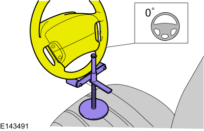
- Position the steering wheel in the straight-ahead position.
- Remove and discard the steering column shaft bolt and disconnect the steering column shaft from the steering gear.
Torque: 46 lb-ft (63 N·m)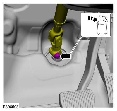
- Remove the wheel and tire.
Refer to: Wheels and Tires (204-04A Wheels and Tires, Removal and Installation). - Remove the fender splash shield.
Refer to: Fender Splash Shield (501-02 Front Body Panels, Removal and Installation). - If equipped.
Remove the clips and the underbody shield.
Torque: 13 lb-in (1.5 N·m)
- If equipped.
Remove the clips and the underbody shield.
Torque: 22 lb-in (2.5 N·m)
- If equipped.
Remove the clips and the underbody shield.
Torque: 22 lb-in (2.5 N·m)
- If equipped, both sides.
Remove the bolt and disconnect the ride height sensor from the front lower arm.
Torque: 97 lb-in (11 N·m)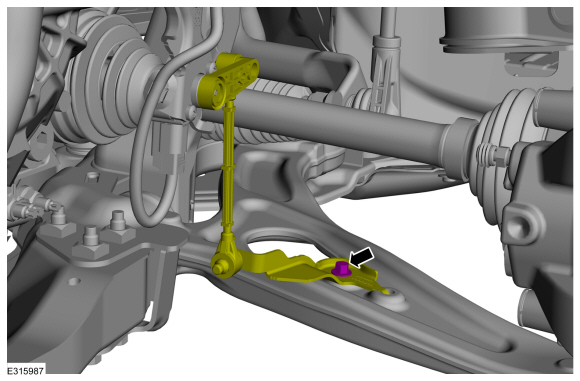
- Remove the front bumper cover.
Refer to: Front Bumper Cover (501-19 Bumpers, Removal and Installation). - Remove the subframe support bracket bolts.
Torque: 22 lb-ft (30 N·m)
- Both sides.
Remove and discard the bolts and remove the front outboard member.
Torque: 30 lb-ft (40 N·m)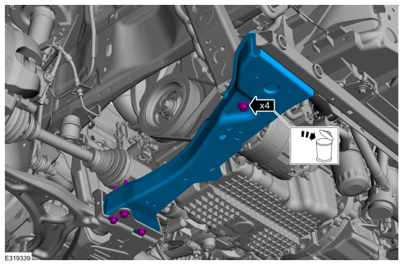
NOTICE: Do not use power tools to remove the stabilizer bar link nut. Damage to the stabilizer bar link ball joint or boot may occur.
Both sides.
Remove and discard the stabilizer bar link lower nuts and position the front stabilizer bar links aside.
Torque: 85 lb-ft (115 N·m)
NOTICE: Do not use a hammer to separate the outer tie rod end from the steering knuckle, otherwise damage to the steering knuckle may occur.
NOTICE: Use care when installing the tie rod separator, as damage to the outer tie rod end boot may occur.
Both sides.
Remove and discard the tie rod end nut and separate the outer tie rod end from the steering knuckle.
Use common equipment: tie rod end remover.
Torque: 35 lb-ft (48 N·m)
NOTICE: Do not use a pry bar to open the slot in the steering knuckle to separate the lower ball joint from the steering knuckle assembly. Damage to the steering knuckle assembly may occur.
NOTICE: Do not use a pry bar or separator fork between the ball joint and steering knuckle. Damage to the ball joint or ball joint seal may occur. Use a pry bar only by inserting it into the lower arm housing hole.
NOTICE: Be careful when releasing the lower arm and steering knuckle, or damage to the ball joint seal may occur.
NOTICE: Do not use power tools to remove or install the lower arm outer nut. Damage to the ball joint or ball joint seal may occur.
Both sides.
Remove and discard the ball joint pinch bolt and nut and separate the lower arm from the steering knuckle.
Torque: 66 lb-ft (90 N·m)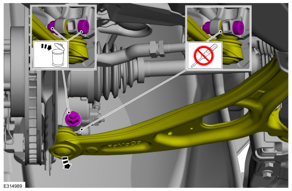
NOTICE: Do not bend or twist the exhaust flex pipe. Failure to follow these instructions may result in damage to the exhaust flex pipe.
Support the flex exhaust pipe.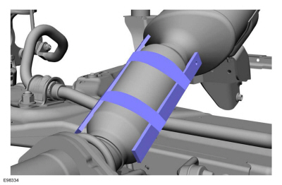
- Remove the bolts and set the exhaust pipe hanger assembly aside.
Torque: 18 lb-ft (25 N·m)
- Remove the engine roll restrictor bolt.
Torque: 129 lb-ft (175 N·m)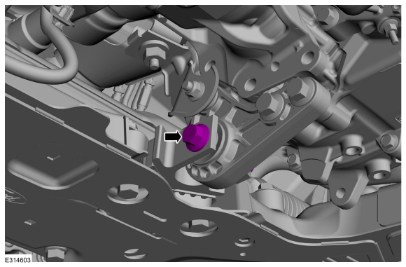
- Disconnect the clips and set the EPAS wiring harness aside.

- Disconnect the wiring harness clips.

- Support the front subframe assembly.
Use common service equipment: transmission jack.
- Both sides
Mark the subframe-to-body location with alignment marks.
- Both sides
Mark the subframe-to-body location with alignment marks.
- Remove and discard the rear subframe bolts.
Torque:
Stage 1: 159 lb-ft (215 N·m)
Stage 2: 120°
- Remove the subframe bolts and brackets.
Torque: 46 lb-ft (63 N·m)
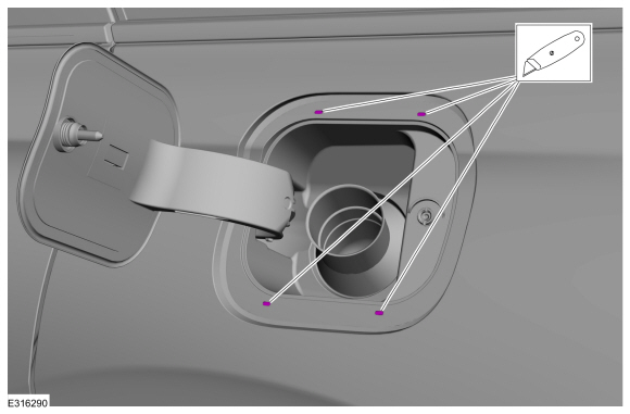
- Remove and discard the rear subframe bolts.
- Remove the front subframe bolts.
Torque: 85 lb-ft (115 N·m)
- Lower the front subframe assembly from the vehicle.
Measurement: 4 in (100 mm)

- Remove the front subframe bolts.
NOTICE: The steering column floor seal is single-use. The seal must be replaced each time the front subframe is lowered or separated from the vehicle.
Remove and discard the steering column floor seal.
- Remove and discard the stabilizer bar bracket bolts and remove the stabilizer bar.
Torque: 46 lb-ft (63 N·m)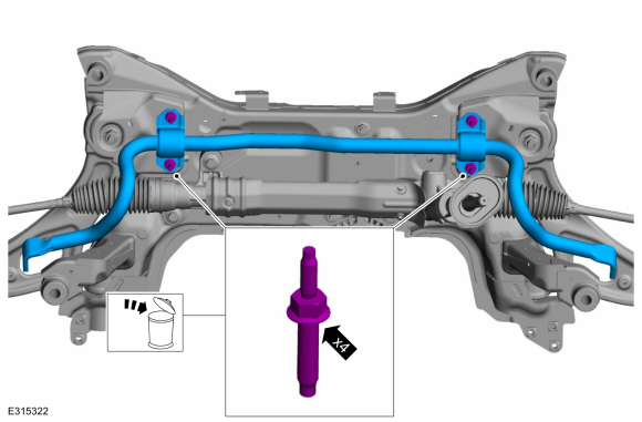
Installation
- To install, reverse the removal procedure.
- Before installation, clean and inspect the steering column floor seal mating surface.
Material: Motorcraft® Metal Brake Parts Cleaner / PM-4-A, PM-4-B, APM-4-C
- Install a new steering column floor seal.
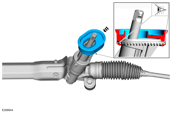
- Check and adjust the front toe if necessary.
Refer to: Front Toe Adjustment (204-00 Suspension System - General Information, General Procedures).
Test yourself
A quick Ford Escape quiz: every answer comes with an explanation and a link to the manual page.