Suspension and steering
Steering angles and wheel alignment
In this manual: Suspension and steering
~4min read
1 Accurate front wheel alignment is essential to good steering and for even tyre wear. Before considering the steering angles, check that the tyres are correctly inflated, that the roadwheels are not buckled, the hub bearings are not worn or incorrectly adjusted and that the steering linkage is in good order.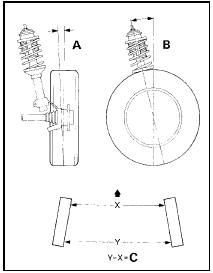
27.2 Wheel alignment diagram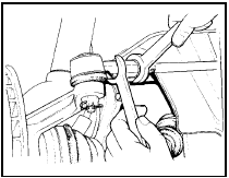
27.5 Slackening tie-rod balljoint locknut for toe setting adjustment 6 Obtain a tracking gauge. These are available in various forms from accessory stores, or one can be fabricated from a length of steel tubing, suitably cranked to clear the sump and bellhousing, and having a setscrew and locknut at one end. 7 With the gauge, measure the distance between the two inner rims of the roadwheels (at hub height) at the rear of the wheel. Push the vehicle forward to rotate the wheel through 180° (half a turn) and measure the distance between the wheel inner rims, again at hub height, at the front of the wheel. This last measurement should differ from the first one by the specified toe-in/toe-out (see “Specifications”). 8 Where the toe setting is found to be incorrect, release the tie-rod balljoint locknuts and turn the tie-rods by an equal amount. Only turn them through a quarter turn at a time before re-checking the alignment. Do not grip the threaded part of the tie-rod during adjustment and make sure that the bellows outboard clip is released, otherwise the bellows will twist as the tie-rod is rotated. When each tie-rod is viewed from the rack housing, turning the rods clockwise will increase the toe-out. Always turn the tie-rods in the same direction when viewed from the centre of the vehicle, otherwise they will become unequal in length. This would cause the steering wheel spoke alignment to alter and also cause problems on turning with tyre scrubbing. 9 On completion of adjustment, tighten the tie-rod balljoint locknuts without altering the setting of the tie-rods. Hold the balljoint assembly at the mid-point of its arc of travel (flats are provided on it for a spanner) while the locknuts are tightened. 10 Finally, tighten the bellows clamps.
2 Wheel alignment consists of four factors (see illustration):
27.2 Wheel alignment diagram
A Camber
B Castor
C Toe setting
5 Adjust, if necessary, by releasing the locknut from the balljoint assembly and the clamp at the small end of the bellows (see illustration).
27.5 Slackening tie-rod balljoint locknut for toe setting adjustment 6 Obtain a tracking gauge. These are available in various forms from accessory stores, or one can be fabricated from a length of steel tubing, suitably cranked to clear the sump and bellhousing, and having a setscrew and locknut at one end. 7 With the gauge, measure the distance between the two inner rims of the roadwheels (at hub height) at the rear of the wheel. Push the vehicle forward to rotate the wheel through 180° (half a turn) and measure the distance between the wheel inner rims, again at hub height, at the front of the wheel. This last measurement should differ from the first one by the specified toe-in/toe-out (see “Specifications”). 8 Where the toe setting is found to be incorrect, release the tie-rod balljoint locknuts and turn the tie-rods by an equal amount. Only turn them through a quarter turn at a time before re-checking the alignment. Do not grip the threaded part of the tie-rod during adjustment and make sure that the bellows outboard clip is released, otherwise the bellows will twist as the tie-rod is rotated. When each tie-rod is viewed from the rack housing, turning the rods clockwise will increase the toe-out. Always turn the tie-rods in the same direction when viewed from the centre of the vehicle, otherwise they will become unequal in length. This would cause the steering wheel spoke alignment to alter and also cause problems on turning with tyre scrubbing. 9 On completion of adjustment, tighten the tie-rod balljoint locknuts without altering the setting of the tie-rods. Hold the balljoint assembly at the mid-point of its arc of travel (flats are provided on it for a spanner) while the locknuts are tightened. 10 Finally, tighten the bellows clamps.
11 For rear wheel alignment refer to Section 19.
Test yourself
A quick Ford Escort quiz: every answer comes with an explanation and a link to the manual page.
Was this page helpful?