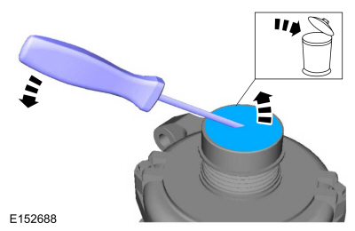
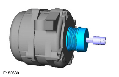
For circuit and connector information, refer to Wiring Diagrams Cell 12.
Normal Operation and Fault Symptoms
With the engine running, the charging system supplies voltage to the battery and the vehicle electrical system through the high-current cable from the BJB and the battery B+. The PCM monitors this B+ voltage through the PCM VPWR or FPPWR circuits. If the charging system voltage is 1.5 volts or more below the required alternator voltage (GENVDSD), a DTC is set and the charging system MIL illuminates after 30 seconds.
DTC Fault Trigger Conditions
| Trouble Code | Description | Fault Trigger Condition |
| PCM P0562:00 |
System Low Voltage: No Sub-type Information |
If the voltage is 1.5 V or more below the required alternator voltage (calculated by the powertrain control module), this DTC is set after 30 seconds. |
| PCM P065B:00 |
Alternator "A" Control Circuit Range/Performance: no subtype information |
This DTC is set when the generator reports an internal regulator fault. |
| PCM P065C:00 |
Alternator "A" Mechanical Performance: no subtype information |
This DTC is set when the generator reports an internal mechanical fault. |
Possible Sources
- Battery
- Fuses or fusible links
- Generator
- PCM
- Wiring, Terminals or Connectors
Visual Inspection and Pre-checks
- Inspect the FEAD system. REFER TO 303-05.
- Check for abnormal current draw with the ignition off.
- Inspect the battery.
- Inspect the high-current BJB for loose, damaged or corroded connections.
- Check the high-current fuse BJB 201 (275 A).
|
| NOTE: Make sure the battery voltage is above 12.2 V before and during this precise test. |
| NOTE: Do not connect a battery charger during vehicle testing. |
| B1 PERFORM INSPECTION AND VERIFICATION |
- Perform the Inspection and Verification procedure in this section.
Was an obvious cause for the observed or reported concern found?
| Yes |
REPAIR the cause if necessary. |
|
| B2 RETRIEVE DIAGNOSTIC TROUBLE CODES (DTCS) |
- Using the diagnostic scan tool, perform a PCM self-test.
Is DTC P065B, P065C, U012D or U042E present?
| Yes |
If DTCs P065B and P065C are present, GO to Pinpoint Test C.
If P065B is present without P065C, INSTALL a new alternator.
Refer to: Alternator - 2.3 L EcoBoost (201 kW/273 L hp) (414-02 Alternator and Regulator, Removal and Installation).
Refer to: Alternator - 3 L EcoBoost (414-02 Alternator and Regulator, Removal and Installation).
Refer to: Alternator - 3.3 L Duratec-V6 (414-02 Alternator and Regulator, Removal and Installation). If U012D or U042E is present, GO to Pinpoint Test G. |
|
| B3 CHECK GENERATOR CONNECTIONS |
- Disconnect all generator connectors and inspect:
- corrosion (install new connector or terminals - clean module pins)
- damaged or bent pins - install new terminals/pins
- backed-out pins - install new pins as necessary
- Connect the generator connectors. Make sure they are fully seated and locked.
- Measure and record:
| Positive lead | Measurement/Action | Negative lead |
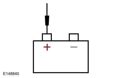 |
 |
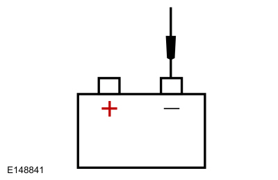 |
- Action:
Click to display the connectors
| Positive lead | Measurement/Action | Negative lead |
| C102A-1 |
|
Ground |
Is the voltage within 0.5 V of the recorded battery voltage?
| No |
TIGHTEN or INSTALL a new alternator B+ nut as necessary.
Refer to: Alternator - 2.3 L EcoBoost (201 kW/273 L hp) (414-02 Alternator and Regulator, Removal and Installation).
Refer to: Alternator - 3 L EcoBoost (414-02 Alternator and Regulator, Removal and Installation).
Refer to: Alternator - 3.3 L Duratec-V6 (414-02 Alternator and Regulator, Removal and Installation).
CHECK the high-current BJB fuse 201 (275A) is OK. If OK, REPAIR the circuit. If not OK, refer to the Wiring Diagrams Manual to determine the possible causes of the short circuit. |
|
| B4 CHECK GENERATOR B+ CIRCUIT VOLTAGE DROP |
- With the engine running at idle, headlamps on and blower motor on high, measure:
Click to display connectors
| Positive lead | Measurement/Action | Negative lead |
| C102A-1 |
|
|
- Perform a wiggle test on the generator wiring and connections while measuring the voltage drop.
Is the voltage drop less than 0.5 volts?
| No |
CHECK and REPAIR any corrosion in the generator B+ circuit or battery positive cable connections. |
|
| B5 CHECK VEHICLE GROUND VOLTAGE DROP |
- With the engine running at idle, headlamps on and blower motor on high, measure:
| Positive lead | Measurement/Action | Negative lead |
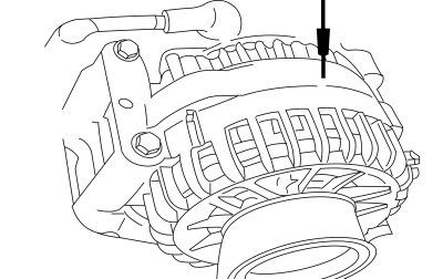 Generator Housing |
|
|
Is the voltage drop less than 0.5 volts?
| No |
CHECK and REPAIR the engine, generator or battery ground for corrosion. |
|
| B6 MONITOR REQUIRED GENERATOR VOLTAGE (GENVDSD) PID (PARAMETER IDENTIFICATION) DURING COMMAND |
- Using the diagnostic scan tool, view the PCM GENVDSD PID.
- Using the diagnostic scan tool commanded function, set the PCM GENVDSD PID to 14 volts.
- With the engine still idling, measure the battery and record:
| Positive lead | Measurement/Action | Negative lead |
|
|
|
Is the recorded battery voltage within ±0.5 V of the PID?
|
| B7 COMPARE PCM VPWR PID (PARAMETER IDENTIFICATION) TO BATTERY VOLTAGE |
- With the engine running at idle, headlamps on and blower motor on high speed, measure and record:
| Positive lead | Measurement/Action | Negative lead |
|
|
|
- Using the diagnostic scan tool, view the PCM PID VPWR.
Does the VPWR PID indicate battery voltage within ±0.5 V of the recorded battery voltage?
| No |
REPAIR high resistance or loose connections in the faulty PCM power supply circuits. |
|
| B8 CHECK PCM (POWERTRAIN CONTROL MODULE) POWER SUPPLY CIRCUITS FOR VOLTAGE |
- Disconnect PCM C1381B (2.3 L EcoBoost), C1551B (3 L EcoBoost) or C175B (3.3 L Duratec).
- Measure and record:
Click to display connectorsFor 2.3 L EcoBoost
| Positive lead | Measurement/Action | Negative lead |
| C1381B-100 |
|
Ground |
| C1381B-101 |
|
Ground |
| C1381B-102 |
|
Ground |
Click to display the connectorsFor 3 L EcoBoost
| Positive lead | Measurement/Action | Negative lead |
| C1551B-1 |
|
Ground |
| C1551B-2 |
|
Ground |
| C1551B-16 |
|
Ground |
Click to display the connectorsFor 3.3 L Duratec
| Positive lead | Measurement/Action | Negative lead |
| C175B-1 |
|
Ground |
| C175B-2 |
|
Ground |
| C175B-16 |
|
Ground |
Are the voltages within 0.5 volts of the recorded battery voltage?
| No |
REPAIR the faulty circuit(s). |
|
| B9 CHECK PCM (POWERTRAIN CONTROL MODULE) GROUND FOR HIGH RESISTANCE |
- NOTE: Measure the battery voltage at the battery. With the engine still running at idle, turn off all auxiliary loads, measure and record:
| Positive lead | Measurement/Action | Negative lead |
|
|
|
- Using the diagnostic scan tool, view the PCM PID VPWR and record.
- With the engine still running at idle, turn on the headlamps and turn on the blower motor to HIGH speed.
- Measure and record:
| Positive lead | Measurement/Action | Negative lead |
|
|
|
- Using the diagnostic scan tool, view the PCM PID VPWR and record.
Does the VPWR PID indicate battery voltage within ±0.5 V with auxiliary loads on and off?
| No |
REPAIR the faulty PCM ground circuit(s). |
|
| B10 MONITOR POWER SUPPLY (VPWR) PID (PARAMETER IDENTIFICATION) |
- NOTE: Measure the battery voltage at the battery. With the engine still idling, turn off all auxiliary loads.
- Measure and record:
| Positive lead | Measurement/Action | Negative lead |
|
|
|
- Using the diagnostic scan tool, view the PCM PID VPWR and record.
- Briefly accelerate the engine to wide open throttle (WOT) and release. Repeat this step 4-5 times while continuing to monitor the PID.
Does the PID remain within 0.5 volts of the recorded battery voltage when engine speed (RPM) increases?
| Yes |
The system is currently operating correctly. The concern may have been caused by a loose or corroded connector. INSPECT and REPAIR any connector or terminal concerns found. If no connector or terminal concerns are found, PERFORM the battery drain test.
Refer to: Battery Drain Test (414-01 Battery, Mounting and Cables, General Procedures). |
|
| B11 CHECK ALTERNATOR DECOUPLER PULLEY OPERATION |
- Perform the alternator decoupler pulley component check. GO to Pinpoint Test H.
Is the alternator decoupler pulley OK?
| Yes |
INSTALL a new alternator.
Refer to: Alternator - 2.3 L EcoBoost (201 kW/273 L hp) (414-02 Alternator and Regulator, Removal and Installation).
Refer to: Alternator - 3 L EcoBoost (414-02 Alternator and Regulator, Removal and Installation).
Refer to: Alternator - 3.3 L Duratec-V6 (414-02 Alternator and Regulator, Removal and Installation). |
| No |
INSTALL a new generator clutch.
Refer to: Generator Pulley (414-02 Generator and Regulator, Removal and Installation). |
|
| B12 CHECK PCM (POWERTRAIN CONTROL MODULE) OPERATION |
- Disconnect and inspect all PCM connectors.
- Repair:
- corrosion (install new connector or terminals - clean module pins)
- damaged or bent pins - install new terminals/pins
- backed-out pins - install new pins as necessary
- Connect the PCM connectors. Make sure they are fully seated and locked.
- Operate the system and determine if the concern is still present.
Is the concern still present?
| Yes |
CHECK OASIS for any applicable Technical Service Bulletins (TSBs). If a TSB exists for this concern, STOP this test and FOLLOW the TSB instructions. If the TSBs do not resolve the concern,
 Click here to access the guided routine (PCM).  Internet Explorer version 11 or later is required to perform this Pinpoint test. |
| No |
The system is currently operating correctly. The concern may have been caused by a loose or corroded connector. ADDRESS the root cause of any connector or pin issues. |
|

 DIAGNOSTIC TEST A: HIGH SYSTEM VOLTAGE