The diagnosis in this manual assumes a certain level of skill and knowledge of Ford-approved diagnostic procedures. REFER TO: Diagnostic Methods (100-00 General Information, Description and Operation).
PCM Diagnostic Trouble Code Chart
Trouble Code
Description
Action
P0125
Insufficient Engine Coolant Temperature for Closed Loop Fuel Control
GO to Pinpoint Test C
P0128
Engine Coolant Thermostat (Engine Coolant Temperature Below Thermostat Regulating Temperature)
GO to Pinpoint Test C
P0217
Engine Coolant Overtemperature Conditions
GO to Pinpoint Test B
P0480
Cooling Fan Control Circuit 1
Refer to the Powertrain Control/Emissions Diagnosis (PC/ED) manual.
P0481
Cooling Fan Control Circuit 2
Refer to the Powertrain Control/Emissions Diagnosis (PC/ED) manual.
P0691
Cooling Fan Control Circuit 1 Low Signal Level
Refer to the Powertrain Control/Emissions Diagnosis (PC/ED) manual.
P0692
Cooling Fan Control Circuit 1 High Signal Level
Refer to the Powertrain Control/Emissions Diagnosis (PC/ED) manual.
P0693
Cooling Fan Control Circuit 2 Low Signal Level
Refer to the Powertrain Control/Emissions Diagnosis (PC/ED) manual.
P0694
Cooling Fan Control Circuit 2 High Signal Level
Refer to the Powertrain Control/Emissions Diagnosis (PC/ED) manual.
P26B7
Engine Coolant Bypass Valve "C" Control Circuit/Open
GO to Pinpoint Test D
P26BD
Engine Coolant Bypass Valve "D" Control Circuit/Open
GO to Pinpoint Test E
All Other PCM Diagnostic Trouble Codes (DTCs)
—
Refer to: Electronic Engine Controls (303-14B Electronic Engine Controls - 1.6 L EcoBoost (132 kW/180 L hp) - Sigma, Diagnosis and Testing).
Inspection and Verification
NOTICE: The engine cooling system is filled with Motorcraft® Orange Antifreeze/Coolant. Always fill the cooling system with the coolant specified by the manufacturer. Chemically flush the cooling system if a coolant not meeting the specification was used. Failure to follow these instructions may damage the engine or the cooling system.
Verify the customer concern.
Visually check the engine coolant level in the coolant recovery reservoir when the system is cold.
Make sure the pressure relief cap is installed correctly.
Record all cooling system diagnostic trouble codes (DTCs). Refer to the PCM DTC Chart in this section for DTC descriptions.
If the cooling system is filled correctly and no fail-safe cooling related DTCs are retrieved, verify the customer concern by starting the engine to duplicate the condition.
Visually check for obvious signs of mechanical or electrical damage.
Visual Inspection Chart
mechanical
Electrical
Leaks or seepage from:
Hoses
hoses
Clamps
Engine Gaskets (internal or external leakage possible)
Thermostat Housing
Radiator
Pressure Relief Cap
Coolant Pump
Turbocharger (may leak internally or externally)
Engine Oil Cooler (may leak internally or externally) (if equipped)
Heater core (wet floor or coolant smell in the vehicle)
Degas bottle
Engine Block Core Plugs
Cylinder Head Core Plugs
Coolant Shutoff Solenoid Valve
Coolant Bypass Solenoid Valve
Engine Block Heater (if equipped)
Transmission Fluid Cooler (may leak internally or externally) (if equipped)
Cracks or damage:
Hoses
hoses
Clamps
Thermostat Housing
Radiator
Pressure Relief Cap
Fan
Coolant Pump
Turbocharger
Engine Oil Cooler (if equipped)
Degas bottle
Engine Block Core Plugs
Cylinder Head Core Plugs
Coolant Shutoff Solenoid Valve
Coolant Bypass Solenoid Valve
Engine Block Heater (if equipped)
Transmission Fluid Cooler (if equipped)
Restricted airflow through the A/C condenser/radiator
Excessive white or light gray exhaust smoke (may have a burnt coolant smell)
Coolant in Engine Oil
Engine oil in the coolant
Inoperative or damaged:
Electric cooling fan
Wiring, connectors, relays or modules
ECT Sensor
Vehicle Speed Sensor (VSS)
If the inspection reveals an obvious concern that can be readily identified, correct as necessary.
Inspect the condition of the coolant.
Check the color of the coolant.
Discoloration may indicate that an incorrect coolant has been added to the system. Using an incorrect (green or yellow colored) coolant degrades the corrosion protection of Motorcraft® Orange Antifreeze/Coolant. If Motorcraft® Specialty Green Engine Coolant has been added, the color may turn a cloudy green-brown. However, adding Motorcraft® Gold Antifreeze/Coolant may not change the color or appearance of the orange coolant. Motorcraft® Gold Antifreeze/Coolant contamination is detected by the presence of nitrites. When Motorcraft® Gold Antifreeze/Coolant contamination is suspected, test the coolant using the HD Antifreeze Coolant 3-Way Test Kit. Follow the nitrite test instructions in the kit to determine whether nitrites are present in the system. If nitrite is present, flush the system and fill with the correct mixture of distilled water and concentrated Motorcraft® Orange Antifreeze/Coolant. REFER TO: Engine Cooling System Draining, Vacuum Filling and Bleeding (303-03B Engine Cooling - 1.6 L EcoBoost (132 kW/180 L PS) - Sigma, General Procedures).
A darker orange color with debris may indicate that a commercially available stop-leak product may have been used. This may cause loss of coolant flow to critical engine components. If sediment is present, flush the system and refill with the correct mixture of distilled water and Motorcraft® Orange Concentrated Antifreeze/Coolant. REFER TO: Engine Cooling System Draining, Vacuum Filling and Bleeding (303-03B Engine Cooling — 1.6 L EcoBoost (132 kW/180 L hp) — Sigma, General Procedures).
A light or reddish-brown color indicates the presence of rust in the cooling system. Flush the system and refill with the correct mixture of distilled water and Motorcraft® Orange Concentrated Antifreeze/Coolant. REFER TO: Engine Cooling System Draining, Vacuum Filling and Bleeding (303-03B Engine Cooling — 1.6 L EcoBoost (132 kW/180 L hp) — Sigma, General Procedures).
A rainbow sheen on the surface of the coolant may indicate oil contamination in the cooling system. For engine diagnosis, REFER TO: Engine (303-00 Engine System — General Information, Diagnosis and Testing). Flush the system and refill with the correct mixture of distilled water and Motorcraft® Orange Antifreeze/Coolant Concentrated. Refer to: Engine Cooling System Draining, Vacuum Filling and Bleeding (303-03B Engine Cooling — 1.6 L EcoBoost (132 kW/180 L hp) — Sigma, General Procedures).
A milky brown color may indicate that engine oil has entered the cooling system. Pressure test the cooling system. Refer to Component Tests in this section. If engine oil contamination is suspected, the leak may be inside the engine. For engine diagnosis, REFER TO: Engine (303-00 Engine System — General Information, Diagnosis and Testing). Flush the system and refill with the correct mixture of distilled water and Motorcraft® Orange Antifreeze/Coolant Concentrated. Refer to: Engine Cooling System Draining, Vacuum Filling and Bleeding (303-03B Engine Cooling — 1.6 L EcoBoost (132 kW/180 L hp) — Sigma, General Procedures).
If the engine coolant appearance is acceptable, check the engine coolant freeze point range with the Coolant/Battery Refractometer. Maintain the engine coolant concentration between 48% and 50%, which corresponds to a freeze protection of -34°C to -37°C (-30°F to -34°F). If the vehicle is operated in cold climates below -37°C (-34°F), it may be necessary to increase the coolant concentration to obtain adequate freeze protection. The recommended coolant concentration is 48/52 to 50/50 (freeze protection from -34°C to -37°C [-30°F to -34°F]) engine coolant to distilled water.
The maximum coolant concentration is 60/40 for cold climate regions.
The minimum coolant concentration is 40/60 for warm climate regions.
If necessary, adjust the coolant concentration and level:
If the coolant concentration is acceptable but the level is low, add only the specified coolant mixture.
If the engine coolant concentration test is too weak, remove some engine coolant and add Motorcraft® Orange Concentrated Antifreeze/Coolant until the readings are within the specified levels.
If the engine coolant concentration test is too strong, remove some engine coolant and add distilled water until the readings are within the specified levels.
If an obvious cause for an observed or reported concern is found, correct the cause and verify proper system operation before proceeding to the next step.
Symptom Chart
The diagnosis in this manual assumes a certain level of skill and knowledge of Ford-approved diagnostic procedures. REFER TO: Diagnostic Methods (100-00 General Information, Description and Operation).
Condition
Possible Sources
Action
Coolant Loss
Refer to Pinpoint Test
GO to Pinpoint Test A
Engine Overheats.
Refer to Pinpoint Test
GO to Pinpoint Test B
Engine Does Not Reach Normal Operating Temperature.
Refer to Pinpoint Test
GO to Pinpoint Test C
The heater module is not operating correctly.
Heater Module Power Cable
Heater Module
CHECK the continuity of all 3 power cable circuits. If the resistance of any circuit exceeds 5 Ohms, INSTALL a new power cable.
CHECK the resistance of the unit heater. If the resistance is not between 30 and 40 ohms, INSTALL a new unit heater.
Electric Cooling Fan Inoperative at one or more speeds or operates incorrectly.
Wiring
Relay
Fuses
Cooling Fan Motor
Cooling Fan Resistor
Refer to the Powertrain Control/Emissions Diagnosis (PC/ED) manual.
Electric Cooling Fan Runs Continuously.
Wiring
Relay
Refer to the Powertrain Control/Emissions Diagnosis (PC/ED) manual.
Noisy electric cooling fan operation.
Foreign Material Contamination
Blower motor
REMOVE the foreign object from the cooling fan and shroud. CHECK the system for normal operation. If still noisy, INSTALL a new cooling fan assembly. REFER TO: Engine Cooling Fan Motor and Shroud (303-03B Engine Cooling — 1.6 L EcoBoost (132 kW/180 L hp) — Sigma, Removal and Installation).
Cooling fan blades disconnected from the fan motor
INSTALL a new cooling fan assembly. REFER TO: Engine Cooling Fan Motor and Shroud (303-03B Engine Cooling — 1.6 L EcoBoost (132 kW/180 L hp) — Sigma, Removal and Installation).
Pinpoint Tests
Coolant Loss
Normal Operation and Failure Conditions
The engine cooling system is a closed system that accommodates coolant expansion and contraction and pressure changes as the coolant heats up and cools down during engine operation. Various gaskets, seals, hoses and clamps keep the coolant in the cooling system and keep other fluids and contaminants out of the cooling system. Coolant loss may be caused by either external or internal leaks anywhere within the cooling system.
Possible Sources
Coolant Hoses or Tubes
Clamps
Thermostat Housing
Thermostat Housing O-rings
Coolant Pump Gasket
Radiator
Pressure Relief Cap
Coolant Pump
Turbocharger (may leak internally or externally)
Oil Cooler (internal or external leakage possible) (if equipped)
Heater Core
Engine Gaskets (internal or external leakage possible)
Degas bottle
Engine Block Core Plugs
Cylinder Head Core Plugs
Coolant Shutoff Solenoid Valve
Coolant Bypass Solenoid Valve
Engine Block Heater (if equipped)
DIAGNOSTIC TEST A: DIAGNOSTIC TEST
WARNING: Always allow the engine to cool before opening the cooling system. Do not remove the coolant pressure relief cap while the engine is running or the cooling system is hot. The cooling system is under pressure; steam and hot coolant can be expelled forcefully when the cap is loosened. Failure to follow these instructions may result in serious injury.
A1 INSPECT AND VERIFY
Inspect and verify.
Is there a concern?
Yes
REPAIR as necessary.
No
GO to A2
A2 CHECK THE ENGINE COOLANT LEVEL AND PRESSURE TEST THE ENGINE COOLING SYSTEM
Ignition OFF.
Visually check the engine coolant level in the degas bottle and adjust if necessary. Pressure test the engine cooling system. Refer to Component Tests, Cooling System Pressure Test in this section.
Is there an external leak in the engine cooling system?
Yes
REPAIR or INSTALL new components.
No
GO to A3
A3 CHECK THE ENGINE COOLANT FOR INTERNAL LEAKAGE
Inspect the engine coolant in the degas bottle for signs of engine oil.
Is engine oil visible in the engine coolant?
Yes
REFER TO: Engine (303-00 Engine System - General Information, Diagnosis and Testing).
No
GO to A4
A4 CHECK THE ENGINE OIL FOR COOLANT CONTAMINATION
Remove the engine oil dipstick.
Is engine coolant visible in the engine oil?
Yes
Pressure test the engine cooling system. Refer to Component Tests, Cooling System Pressure Test in this section.
No
GO to A5
A5 CHECK THE COOLING SYSTEM FOR EXHAUST GAS
Using the Cooling System Combustion Gas Tester, follow the instructions supplied with the tester, check the engine coolant for combustion gases.
Are combustion gases present?
Yes
REFER TO: Engine (303-00 Engine System - General Information, Diagnosis and Testing).
No
Cooling System Operation
Engine Overheats
Normal Operation and Failure Conditions
The engine cooling system maintains engine temperature during operation. Correct coolant flow through the engine, radiator and other cooling system passages and components is necessary to maintain correct engine temperature.
The engine coolant flows mainly from the engine to the radiator circuit and back to the coolant pump. Coolant is supplied from the coolant pump through the cylinder block and cylinder heads. A separate circuit from the engine also supplies coolant to the heater core. The coolant pump circulates the coolant. The coolant thermostat is a control valve actuated by coolant temperature. When the thermostat is closed, coolant flow bypasses the radiator circuit and returns to the coolant pump. When the thermostat opens, coolant flows through the radiator circuit to transfer heat generated by the engine to the outside air.
The engine cooling system includes a coolant bypass solenoid valve and a coolant shutoff solenoid valve. Using these two valves, the coolant flow through the engine block can be restricted or completely stopped. Restricting or stopping the coolant flow allows engine components to warm up faster during the warm-up phase. The coolant shutoff solenoid valve is normally open and closes when power is applied to stop coolant flow throughout the cooling system, if the coolant bypass solenoid valve is also closed. The coolant shutoff solenoid valve blocks or allows coolant flow through the thermostat housing, coolant pump, cylinder block, heater core, turbocharger, transmission oil cooler and engine oil cooler. The coolant bypass solenoid valve provides another coolant circuit for the cylinder block; it is normally closed and opens when power is applied to allow coolant flow between the engine block outlet and the thermostat housing. The main function of this valve is to increase coolant flow through the engine block, reducing pressure and temperature fluctuations in the cooling system under high engine loads. If one or both valves do not open on command, the PCM may cause the engine to overheat.
Engine overheating normally occurs when the ability to control any coolant flow at the correct rate is disrupted, when heat cannot be transferred from the engine through the coolant (including engine oil), or when heat generated by the engine cannot be transferred to the outside air through the radiator.
Possible Sources
Low coolant level
Engine coolant external leakage
Air trapped in the system
Pressure relief cap installation
Restricted airflow through the A/C condenser/radiator
Set in the PCM when the ECT sensor detects an engine overheating condition.
DIAGNOSTIC TEST B: DIAGNOSTIC TEST
B1 INSPECTION AND VERIFICATION
Complete the inspection and verification procedure described in this section.
Is there a concern?
Yes
REPAIR as necessary.
No
GO to B2
B2 CHECK THE PCM (POWERTRAIN CONTROL MODULE) FOR DTCS
The ignition is on.
Using a scan tool, perform the PCM self-test.
Is DTC P0217 present?
Yes
GO to B3
No
Actual engine overheating is not confirmed. CHECK the operation of the engine coolant temperature gauge. REFER TO: Instrument Cluster, Message Center and Warning Chimes (413-01 Instrument Cluster, Message Center and Warning Chimes, Diagnosis and Testing). If any other PCM DTCs are present, Refer to: Engine Control System (303-14B Electronic Engine Controls — 1.6 L EcoBoost (132 kW/180 L PS) — Sigma, Diagnosis and Testing).
B3 REVIEW PCM (POWERTRAIN CONTROL MODULE) DTCS
Check DTC P26B7 or P26BD.
Is DTC P26B7 or P26BD present?
Yes
For DTC P26B7, GO to Location Test D. For DTC P26BD, GO to Location Test E.
No
GO to B4
B4 CHECK FOR AIRFLOW OBSTRUCTION
Inspect the radiator or A/C condenser for external obstructions such as leaves or cardboard.
Is an obstruction present?
Yes
REMOVE the obstruction.
No
GO to B5
B5 CHECK THE ELECTRIC COOLING FAN OPERATION
Start the engine.
Set the climate control function selector to MAX A/C and the fan switch to HI.
Did the electric cooling fan operate?
Yes
GO to B6
No
CHECK the operation of the electric cooling fan. Refer to the Powertrain Control/Emissions Diagnosis (PC/ED) manual, Section 3 Symptom Charts.
B6 CHECK THE ENGINE COOLANT LEVEL AND PRESSURE TEST THE COOLING SYSTEM
Ignition OFF.
Visually check the engine coolant level in the coolant recovery reservoir and adjust if necessary. Pressure test the cooling system.
Is there an external leak in the engine cooling system?
Yes
REPAIR or INSTALL new components.
No
GO to B7
B7 CHECK THE ENGINE COOLANT FOR INTERNAL LEAKAGE
Inspect the engine coolant in the coolant recovery reservoir for signs of engine oil.
Is engine oil visible in the coolant?
Yes
REFER TO: Engine (303-00 Engine System - General Information, Diagnosis and Testing).
No
GO to B8
B8 CHECK THE ENGINE OIL FOR COOLANT CONTAMINATION
Remove the engine oil dipstick.
Is engine coolant visible in the engine oil?
Yes
REFER TO: Engine (303-00 Engine System - General Information, Diagnosis and Testing).
No
GO to B9
B9 CHECK THE COOLING SYSTEM FOR EXHAUST GAS
Using the Cooling System Combustion Gas Tester, follow the instructions supplied with the tester, check the engine coolant for combustion gases.
Are combustion gases present?
Yes
REFER TO: Engine (303-00 Engine System - General Information, Diagnosis and Testing).
No
GO to B10
B10 CHECK THE CONDITION OF THE ENGINE COOLANT
Check the engine coolant for dirt, rust or contamination and check the engine coolant concentration.
Is the engine coolant condition satisfactory?
Yes
GO to B11
No
FLUSH the engine cooling system.
B11 CHECK THE COOLANT SHUTOFF SOLENOID VALVE FOR STUCK CLOSED
Start the engine.
Allow the engine to warm up to operating temperature.
Visually check the coolant flow in the coolant recovery reservoir.
Is coolant flow present?
Yes
GO to B12
No
INSTALL a new coolant shutoff solenoid valve. REFER TO: Coolant Shutoff Solenoid Valve (303-03B Engine Cooling — 1.6 L EcoBoost (132 kW/180 L PS) — Sigma, Removal and Installation). Fill and bleed the cooling system. REFER TO: Engine Cooling System Draining, Vacuum Filling and Air Bleeding (303-03B Engine Cooling — 1.6 L EcoBoost (132 kW/180 L PS) — Sigma, General Procedures). Repeat the precise test step. If there is still no flow in the reservoir, check the reservoir for blocked coolant hoses, heater core or engine oil cooler lines. If no blockage is found, install a new coolant pump. REFER TO: Coolant Pump (303-03B Engine Cooling — 1.6 L EcoBoost (132 kW/180 L PS) — Sigma, Removal and Installation).
B12 CHECK THE COOLANT BYPASS SOLENOID VALVE FOR STUCK OPEN
Start the engine or perform a road test to recreate the overheating condition.
Feel the coolant bypass hose between the coolant bypass solenoid valve at the rear of the cylinder head and the thermostat housing.
Is the bypass hose cold to the touch?
Yes
INSTALL a new coolant bypass solenoid valve. REFER TO: Coolant Bypass Solenoid Valve (303-03B Engine Cooling — 1.6 L EcoBoost (132 kW/180 L PS) – Sigma, Removal and Installation).
No
GO to B13
B13 VISUALLY INSPECT THE THERMOSTAT
Perform a visual inspection of the thermostat in the Component Testing section of this section.
Is the thermostat damaged?
Yes
INSTALL a new thermostat. REFER TO: Thermostat (303-03B Engine Cooling — 1.6 L EcoBoost (132 kW/180 L PS) — Sigma, Removal and Installation).
No
INSTALL a new thermostat. REFER TO: Thermostat (303-03B Engine Cooling — 1.6 L EcoBoost (132 kW/180 L PS) — Sigma, Removal and Installation). If the engine still overheats, INSTALL a new radiator. REFER TO: Radiator (303-03B Engine Cooling — 1.6 L EcoBoost (132 kW/180 L PS) — Sigma, Removal and Installation).
Engine Does Not Reach Normal Operating Temperature
Normal Operation and Failure Conditions
The engine cooling system maintains engine temperature during operation. Correct coolant flow through the engine, radiator and the remainder of the cooling system passages and components is essential to maintain correct engine temperature.
Engine coolant flows mainly from the engine to the radiator circuit and back to the coolant pump. Coolant is supplied from the coolant pump through the cylinder block and cylinder heads. A separate circuit from the engine also supplies coolant to the heater core. The coolant pump circulates the coolant. The coolant thermostat is a coolant-operated control valve that responds to coolant temperature. When the thermostat is closed, coolant flow bypasses the radiator circuit and returns to the coolant pump. When the thermostat opens, coolant flows through the radiator circuit to transfer engine heat to the outside air.
A concern that the engine does not reach normal operating temperature typically occurs when coolant flow through certain circuits (radiator, heater core) is greater than expected for the conditions. The heat exchangers cannot be built into the engine, because they remove too much heat, including the radiator, heater core and oil cooler. In addition, a concern that the engine does not reach normal operating temperature may be related to low coolant level or trapped air that prevents hot coolant from reaching the heater core, an inoperative climate control system, or concerns perceived or related to an incorrect engine temperature sensor indication.
The engine cooling system includes a coolant bypass solenoid valve and a coolant shutoff solenoid valve. Using these two valves, coolant flow through the engine block can be restricted or completely stopped. Restricting or stopping coolant flow allows engine components to warm up faster during the warm-up phase. The coolant shutoff solenoid valve is normally open and closes when powered to stop coolant flow throughout the cooling system if the coolant bypass solenoid valve is closed. The coolant shutoff solenoid valve blocks or passes coolant through the thermostat housing, coolant pump, cylinder block, heater core, turbocharger, transmission oil cooler and engine oil cooler. The coolant bypass solenoid valve provides a separate coolant circuit for the cylinder block and is normally closed and opens when powered to allow coolant flow between the engine block outlet and the thermostat housing. The main function of this valve is to increase coolant flow through the engine block to reduce cooling system pressure and temperature fluctuations under high engine loads. The coolant bypass solenoid valve is commanded open at high engine temperatures to provide more cooling. If the coolant bypass solenoid valve mechanically sticks in the open position, the engine takes longer to reach operating temperature.
Insufficient Engine Coolant Temperature for Closed Loop Fuel Control
Set in the PCM when the ECT sensor has not reached the required temperature level to enter closed loop operating conditions within a specified time after engine start.
P0128
Engine Coolant Thermostat (Engine Coolant Temperature Below Thermostat Regulating Temperature)
Set in the PCM when the thermostat monitor does not reach the required engine operating temperature within a specified time after engine start.
DIAGNOSTIC TEST C: DIAGNOSTIC TEST
WARNING: Always allow the engine to cool before opening the cooling system. Do not remove the coolant pressure relief cap while the engine is running or the cooling system is hot. The cooling system is under pressure; steam and hot coolant can be expelled forcefully when the cap is loosened. Failure to follow these instructions may result in serious injury.
C1 PERFORM INSPECTION AND CHECKS
Complete the inspection and verification procedure described in this section.
Were any concerns found?
Yes
REPAIR as necessary.
No
GO to C2
C2 CHECK DTC (DIAGNOSTIC TROUBLE CODE) P0125 OR P0128
The ignition is on.
Using a scan tool, perform the PCM self-test.
Is DTC P0125 or P0128 present?
Yes
GO to C3
No
The cooling system is operating. If a malfunctioning temperature sensor is suspected, CHECK the operation of the temperature sensor. REFER TO: Instrument Cluster, Message Center and Warning Chimes (413-01 Instrument Cluster, Message Center and Warning Chimes, Diagnosis and Testing). If a climate control system malfunction is suspected, CHECK the operation of the climate control system. For EATC REFER TO: Climate Control System — Vehicles With: Electronic Automatic Temperature Control (EATC) (412-00 Climate Control System - General Information, Diagnosis and Testing). For Electronic Manual Temperature Control (EMTC) REFER TO: Climate Control System — Vehicles With: Electronic Manual Temperature Control (EMTC) (412-00 Climate Control System - General Information, Diagnosis and Testing). If other diagnostic trouble codes (DTCs) are found, REFER TO: Engine Control System — Electronic (303-14B Electronic Engine Controls — 1.6 L EcoBoost (132 kW/180 L PS) — Sigma, Diagnosis and Testing).
C3 REVIEW PCM (POWERTRAIN CONTROL MODULE) DTCS
Check DTC P26B7 or P26BD.
Is DTC P26B7 or P26BD present?
Yes
For DTC P26B7, GO to Location Test D. For DTC P26BD, GO to Location Test E.
No
GO TO C4
C4 CHECK THE COOLANT LEVEL
Visually check the engine coolant level in the coolant recovery reservoir.
Is the engine coolant level within specification?
Yes
GO to C5
No
GO to Pinpoint Test A
C5 CHECK THE COOLANT BYPASS SOLENOID VALVE FOR STUCK OPEN
Start the engine.
Allow the engine to idle and reach normal operating temperature (if cold).
Feel the coolant hose between the coolant bypass solenoid valve and the thermostat housing.
Is the coolant hose hot?
Yes
INSTALL a new coolant bypass solenoid valve. REFER TO: Coolant Bypass Solenoid Valve (303-03B Engine Cooling — 1.6 L EcoBoost (132 kW/180 L PS) – Sigma, Removal and Installation).
Using an infrared temperature gun, measure and record the coolant outlet temperature at the rear of the cylinder head next to the ECT sensor.
Is the temperature reading similar to the ECT PID value?
Yes
INSTALL a new thermostat. REFER TO: Thermostat (303-03B Engine Cooling — 1.6 L EcoBoost (132 kW/180 L PS) — Sigma, Removal and Installation).
No
INSTALL a new ECT sensor. REFER TO: Engine Coolant Temperature (ECT) Sensor (303-14B Electronic Engine Controls — 1.6 L EcoBoost (132 kW/180 L PS) – Sigma, Removal and Installation).
P26B7
For circuit and connector information, refer to Section 25 of the Electrical Circuit Diagrams.
Normal Operation and Failure Conditions
The engine cooling system includes a coolant bypass solenoid valve and a coolant shutoff solenoid valve. These two valves can restrict or completely stop the coolant flow through the engine block. Restricting or stopping coolant flow allows engine components to warm up faster during the warm-up phase. Both solenoid valves are controlled by the PCM through a low-side driver. The PCM monitors both solenoids for electrical faults and sets the corresponding diagnostic trouble code.
Engine Coolant Bypass Valve "C" Control Circuit/Open
The PCM monitors the engine coolant bypass valve control circuit "C" for high and low voltage open/short. The test fails if the voltage exceeds the calibrated limit for a calibrated amount of time.
DIAGNOSTIC TEST D: DIAGNOSTIC TEST
WARNING: Always allow the engine to cool before opening the cooling system. Do not remove the coolant pressure relief cap while the engine is running or the cooling system is hot. The cooling system is under pressure; steam and hot coolant can be expelled forcefully when the cap is loosened. Failure to follow these instructions may result in serious injury.
D1 CHECK THE COOLANT BYPASS SOLENOID VALVE CONNECTOR FOR FULL ENGAGEMENT
Make sure the coolant bypass solenoid valve C1918 is fully seated.
Were any concerns found?
Yes
REPAIR as necessary.
No
GO to D2
D2 CHECK THE COOLANT BYPASS SOLENOID VALVE RESISTANCE
Disconnect the coolant bypass solenoid valve C1918.
Action: Click to display the connectors
Positive lead
Measurement/Action
Negative lead
pin 1 (component side)
pin 2 (component side)
Is the resistance 9-12 ohms?
Yes
GO to D3
No
INSTALL a new coolant bypass solenoid valve. REFER TO: Coolant Bypass Solenoid Valve (303-03B Engine Cooling — 1.6 L EcoBoost (132 kW/180 L PS) – Sigma, Removal and Installation).
D3 CHECK THE COOLANT BYPASS SOLENOID VALVE VOLTAGE
The ignition is on.
Action: Click to display the connectors
Positive lead
Measurement/Action
Negative lead
C1918-2
Ground
Is the voltage greater than 11 volts?
Yes
GO to D4
No
CHECK the BJB fuse 24 (10A) is OK. If the fuse is OK, REPAIR the circuit. If not OK, REFER to the Electrical Circuit Diagrams to determine the possible causes of the short circuit.
D4 CHECK THE COOLANT BYPASS SOLENOID VALVE CIRCUIT FOR A SHORT TO POWER
Ignition OFF.
Disconnect the PCM C1915E.
The ignition is on.
Action: Click to display the connectors
Positive lead
Measurement/Action
Negative lead
C1918-1
Ground
Is there voltage present?
Yes
REPAIR the circuit.
No
GO to D5
D5 CHECK THE COOLANT BYPASS SOLENOID VALVE CIRCUIT FOR A SHORT TO GROUND
Ignition OFF.
Action: Click to display the connectors
Positive lead
Measurement/Action
Negative lead
C1918-1
Ground
Is the resistance greater than 10,000 ohms?
Yes
GO to D6
No
REPAIR the circuit.
D6 CHECK THE COOLANT BYPASS SOLENOID VALVE CIRCUIT FOR AN OPEN
Action: Click to display the connectors
Positive lead
Measurement/Action
Negative lead
C1918-1
C1915E-2
Is the resistance less than 3 ohms?
Yes
INSTALL a new coolant bypass solenoid valve. REFER TO: Coolant Bypass Solenoid Valve (303-03B Engine Cooling — 1.6 L EcoBoost (132 kW/180 L PS) – Sigma, Removal and Installation). CLEAR the DTC. CHECK the system for normal operation. If the DTC is still present, GO to D7.
No
GO to D7
D7 CHECK THE PCM (POWERTRAIN CONTROL MODULE) FOR PROPER OPERATION
Ignition OFF.
Disconnect and inspect all PCM connectors.
Repair:
corrosion (install new connector or terminals - clean module pins)
damaged or bent terminals/pins - install new terminals/pins
pushed-out pins - install new pins as necessary
Connect the PCM connectors. Make sure they are fully seated and locked.
Operate the system and determine if the concern is still present.
Is the concern still present?
Yes
CHECK OASIS for any applicable Technical Service Bulletins (TSBs). If a TSB exists for this condition, discontinue this test and follow the TSB instructions. If no TSBs apply to this concern, Click here to access the guided routine (PCM).
No
The system is currently operating correctly. The concern may have been caused by module connections. Refer to the root cause of any connector or terminal issues.
P26BD
For circuit and connector information, refer to Section 25 of the Electrical Circuit Diagrams.
Normal Operation and Failure Conditions
The engine cooling system includes a coolant bypass solenoid valve and a coolant shutoff solenoid valve. These two valves can restrict or completely stop the coolant flow through the engine block. Restricting or stopping coolant flow allows engine components to warm up faster during the warm-up phase. Both solenoid valves are controlled by the PCM through a low-side driver. The PCM monitors both solenoids for electrical faults and sets the corresponding diagnostic trouble code.
Engine Coolant Bypass Valve "D" Control Circuit/Open
The PCM monitors the engine coolant bypass valve control circuit "D" for high and low voltage open/short. The test fails if the voltage exceeds the calibrated limit for a calibrated amount of time.
DIAGNOSTIC TEST E: DIAGNOSTIC TEST
WARNING: Always allow the engine to cool before opening the cooling system. Do not remove the coolant pressure relief cap while the engine is running or the cooling system is hot. The cooling system is under pressure; steam and hot coolant can be expelled forcefully when the cap is loosened. Failure to follow these instructions may result in serious injury.
E1 CHECK THE COOLANT SHUTOFF SOLENOID VALVE CONNECTOR FOR FULL ENGAGEMENT
Make sure the coolant shutoff solenoid valve C1919 is fully seated.
Were any concerns found?
Yes
REPAIR as necessary.
No
GO to E2
E2 CHECK THE COOLANT SHUTOFF SOLENOID VALVE RESISTANCE
Disconnect the coolant shutoff solenoid valve C1919.
Action: Click to display the connectors
Positive lead
Measurement/Action
Negative lead
pin 1 (component side)
pin 2 (component side)
Is the resistance 9-12 ohms?
Yes
GO to E3
No
INSTALL a new coolant shutoff solenoid valve. REFER TO: Coolant Shutoff Solenoid Valve (303-03B Engine Cooling — 1.6 L EcoBoost (132 kW/180 L PS) – Sigma, Removal and Installation).
E3 CHECK THE COOLANT SHUTOFF SOLENOID VALVE VOLTAGE
The ignition is on.
Action: Click to display the connectors
Positive lead
Measurement/Action
Negative lead
C1919-2
Ground
Is the voltage greater than 11 volts?
Yes
GO to E4
No
CHECK the BJB fuse 24 (10A) is OK. If the fuse is OK, REPAIR the circuit. If not OK, REFER to the Electrical Circuit Diagrams to determine the possible causes of the short circuit.
E4 CHECK THE COOLANT SHUTOFF SOLENOID VALVE CIRCUIT FOR A SHORT TO POWER
Ignition OFF.
Disconnect the PCM C1915E.
The ignition is on.
Action: Click to display the connectors
Positive lead
Measurement/Action
Negative lead
C1919-1
Ground
Is there voltage present?
Yes
REPAIR the circuit.
No
GO to E5
E5 CHECK THE COOLANT SHUTOFF SOLENOID VALVE CIRCUIT FOR A SHORT TO GROUND
Ignition OFF.
Action: Click to display the connectors
Positive lead
Measurement/Action
Negative lead
C1919-1
Ground
Is the resistance greater than 10,000 ohms?
Yes
GO to E6
No
REPAIR the circuit.
E6 CHECK THE COOLANT SHUTOFF SOLENOID VALVE CIRCUIT FOR AN OPEN
Action: Click to display the connectors
Positive lead
Measurement/Action
Negative lead
C1919-1
C1915B-46
Is the resistance less than 3 ohms?
Yes
INSTALL a new coolant shutoff solenoid valve. REFER TO: Coolant Shutoff Solenoid Valve (303-03B Engine Cooling — 1.6 L EcoBoost (132 kW/180 L PS) – Sigma, Removal and Installation). CLEAR the DTC. CHECK the system for normal operation. If the DTC is still present, GO to E7.
No
GO to E7
E7 CHECK THE PCM (POWERTRAIN CONTROL MODULE) OPERATION
Ignition OFF.
Disconnect and inspect all PCM connectors.
Repair:
corrosion (install new connector or terminals - clean module pins)
damaged or bent terminals/pins - install new terminals/pins
pushed-out pins - install new pins as necessary
Connect the PCM connectors. Make sure they are fully seated and locked.
Operate the system and determine if the concern is still present.
Is the concern still present?
Yes
CHECK OASIS for any applicable Technical Service Bulletins (TSBs). If a TSB exists for this condition, discontinue this test and follow the TSB instructions. If no TSBs apply to this concern, Click here to access the guided routine (PCM).
No
The system is currently operating correctly. The concern may have been caused by module connections. Refer to the root cause of any connector or terminal issues.
Component Tests
Cooling System Pressure Test
TURN the engine OFF.
Check the engine coolant level and adjust as necessary.
Remove the coolant recovery reservoir cap. Inspect the coolant recovery reservoir cap and reservoir for any conditions that could cause improper sealing, such as cross-threading, burrs, a damaged O-ring, etc. If any concerns are found, INSTALL a new cap and/or coolant recovery reservoir.
Attach the pressure tester and adapter (Snap-On TA53 or equivalent) to the coolant recovery reservoir cap. The cap must hold the specified pressure. REFER TO: Specifications (303-03B Engine Cooling — 1.6 L EcoBoost (132 kW/180 L PS) – Sigma, Specifications). If any concerns are found, INSTALL a new cap.
Install the degas bottle cap and allow the engine to run until normal operating temperature is reached.
Turn the engine off.
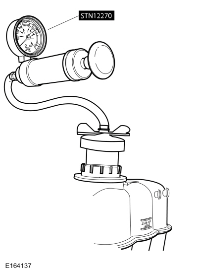
Attach the pressure tester and adapter (Snap-On TA52, ACT ASSF3-47, Redline RDL95-0750 or equivalent) to the degas bottle.
To build pressure in the engine cooling system, slowly pump the pressure test pump plunger and increase the pressure to 145 kPa (21 psi). Allow the system to stabilize for approximately 2 minutes. Raise the pressure to 21 psi. The pressure must not drop during the following 2 minutes. If the pressure drops, check for external leaks and repair as necessary.
Allow the vehicle to stand for a minimum of 5 hours or overnight.
If the pressure drops more than the expected range of 2-4 psi and no external leaks are found, the leak may be internal to the engine. Using a borescope, remove the spark plugs and inspect the cylinder combustion chambers for coolant intrusion. REFER TO: Engine (303-00 Engine System - General Information, Diagnosis and Testing).
If the cooling system pressure is maintained, remove the cooling system pressure tester and the degas bottle adapter.
Install the degas bottle cap until it contacts the stop.
Thermostat
Install a new thermostat only after performing at least one of the following tests and inspections:
Precise Test B or C
Visual Inspection of the Thermostat
Visual Inspection of the Thermostat
Remove the thermostat.
Inspect the thermostat for signs of damage, including:
Valve not fully seated (light visible through the valve)
Foreign object lodged in the main valve
Bent or broken frame or flange
Bent or broken spring
Wax leakage from the wax element or a bulge in the element
Any other damage or distortion
If damage is found during the inspection, remove all foreign objects or debris and install a new thermostat.
Radiator Leak Test, Removed from the Vehicle
NOTICE: Never leak test an aluminum radiator in the same tank of water in which copper/brass radiators are tested. Fluxes and caustic cleaners may be present in the tank and will damage the aluminum radiator.
Check the radiator for leaks by submerging it in clean water and applying air pressure up to the maximum value specified in the Specifications table.
?
Test yourself
A quick Ford Fiesta quiz: every answer comes with an explanation and a link to the manual page.


 WARNING: Always allow the engine to cool before opening the cooling system. Do not remove the coolant pressure relief cap while the engine is running or the cooling system is hot. The cooling system is under pressure; steam and hot coolant can be expelled forcefully when the cap is loosened. Failure to follow these instructions may result in serious injury.


 Click here to access the guided routine (PCM).