Suspension - Diagnosis and Testing
Preliminary Inspection
- Road test the vehicle.
- If there are any concerns with suspension alignment or ground clearance, GO to Symptom Chart - Suspension System.
- Confirm the customer concern by road testing on a smooth road. If any vibration is present, GO to Symptom Chart - NVH.
- Inspect the tires.
- Check the tire pressures under all normal vehicle loads and on cold tires. Refer to the VC label.
- Make sure all tire sizes are to specification. Refer to the VC label.
- Inspect the tires for abnormal wear and damage. Install new tires as necessary.
- Inspect the chassis and underbody.
- Remove excessive accumulations of dirt, mud or road debris from the chassis and underbody.
- Front or rear suspension components
- Suspension Mount(s)
- Spring Misuse
- Spring(s)
- Shock Absorber(s)
- Strut(s)
- Suspension Bushing(s)
- Steering System Components
- Subframe
- Wheel Bearing and Wheel Hub
- Tires
- Non-OEM Parts or Modifications
- Check aftermarket accessories.
- Check for aftermarket modifications to the steering, suspension, wheel and tire components (such as competition or heavy duty). The specifications provided in this manual do not apply to vehicles equipped with aftermarket accessories.
Symptom Chart - Suspension System
The diagnosis in this manual assumes a certain level of skill and knowledge of Ford-approved diagnostic procedures.
REFER TO: Diagnostic Methods (100-00 General Information, Description and Operation).
| Condition | Possible Sources | Action |
|---|---|---|
| Vehicle Drifts / Pulls | Unevenly loaded or overloaded vehicle | GO to Pinpoint Test A |
| Tires/Tire Pressure | ||
| Alignment Out of Specification | ||
| Brake drag | ||
| Steering components | ||
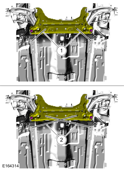
| Subframe Misalignment | ||
| Wander | Overloaded, unevenly loaded or improperly loaded vehicle | NOTIFY the customer of improper vehicle loading. |
| Ball joint(s) | CHECK the ball joints. REFER to the ball joint check component test in this section. | |
| Front strut mount bearing(s) damaged or missing | INSTALL new front strut bearing(s) as necessary. REFER to: Front Strut and Spring Assembly (204-01 Front Suspension, Disassembly and Assembly). |
|
| Loose, worn or damaged front wheel bearing(s) | CHECK the wheel bearings. INSTALL new wheel bearings as necessary. REFER to: Front Wheel Bearing (204-01 Front Suspension, Removal and Installation). |
|
| Loose, worn or damaged suspension components | INSTALL new suspension component(s) as necessary. Refer to the appropriate section in Group 204 for the procedure. | |
| Loose suspension mounts | CHECK the suspension mounts. TIGHTEN to specification. Refer to the appropriate section in Group 204 for the procedure. | |
| Steering components | CHECK the steering system. INSTALL new components as necessary. Refer to the appropriate section in Group 211 for the procedure. | |
| Toe-out-on-turns or excessive total toe (excessive overall front toe) | ADJUST as necessary. REFER TO: Front Wheel Alignment Adjustment (204-00 Suspension System - General Information, General Procedures). |
|
| Front End or Low Ride | Worn, damaged or incorrect springs | MEASURE the ride height. REFER TO: Ride Height Measurement (204-00 Suspension System - General Information, General Procedures). INSTALL new springs as necessary. REFER TO: Front Strut and Spring Assembly Installation (204-01 Front Suspension, Disassembly and Assembly). |
| Worn front strut(s) | INSTALL new struts as necessary. REFER TO: Front Strut and Spring Assembly (204-01 Front Suspension). |
|
| Abnormal/Improper Tire Wear | Incorrect tire pressure (rapid wear of the center rib or inner and outer edges) | ADJUST the tire pressure. REFER TO the VC label. REFER TO Diagnosis and Testing for further diagnosis of tire wear. |
| Incorrect tire rotation intervals | For the procedure, refer to the appropriate section in Group 103. | |
|
REFER TO: Wheels and Tires (204-04A Wheels and Tires, Diagnosis and Testing). for further diagnosis of tire wear. |
|
| Front or rear suspension components | INSPECT the front and rear suspension system. REPAIR or INSTALL new suspension components as necessary. Refer to the appropriate section in Group 204 for the procedure. | |
| Steering Binds, Poor Returnability | Damaged or worn front strut mount bearing(s) | INSTALL new front strut bearing(s) as necessary. REFER to: Front Strut and Spring Assembly (204-01 Front Suspension, Disassembly and Assembly). |
| Ball joint binding | REFER TO the ball joint check test in this section. | |
| Steering components | CHECK the steering system. INSTALL new components as necessary. Refer to the appropriate section in Group 211 for the procedure. | |
| Steering Wheel Off Center | Unequal front or rear toe (side-to-side) | CHECK the wheel alignment. REFER TO: Front Wheel Alignment Adjustment (204-00 Suspension System - General Information, General Procedures). ADJUST as necessary. |
| Steering components | CHECK the steering system. INSTALL new components as necessary. Refer to the appropriate section in Group 211 for the procedure. | |
| Bounce or Shake | Overloaded, unevenly loaded or improperly loaded vehicle | NOTIFY the customer of improper vehicle loading. |
| Loose wheel nuts | TIGHTEN the wheel nuts to specification. REFER TO: Specifications (204-04A Wheels and Tires, Specifications). |
|
| Strut(s) or shock absorber(s) | INSTALL new struts or shock absorbers as necessary. REFER TO: Front Strut and Spring Assembly (204-01 Front Suspension). or REFER TO: Rear Shock Absorber (204-02 Rear Suspension). |
|
| Stabilizer bar bracket-to-frame bolts loose | TIGHTEN the bolts to specification. For the procedure, refer to the appropriate section in Group 204. | |
| Worn stabilizer bar bushings or links | INSTALL new stabilizer bar bushings or links as necessary. REFER TO: Front Stabilizer Bar Bushing (204-01 Front Suspension). |
|
| Damaged or broken stabilizer bar | INSTALL a new stabilizer bar as necessary. REFER TO: Front Stabilizer Bar (204-01 Front Suspension, Removal and Installation). |
|
| Worn spring(s) | INSTALL new springs as necessary. REFER TO: Front Strut and Spring Assembly (204-01 Front Suspension, Disassembly and Assembly). or REFER TO: Spring (204-02 Rear Suspension). |
|
| Vehicle Leans to One Side | Unevenly loaded or overloaded vehicle | NOTIFY the customer of improper vehicle loading. |
| Front or rear suspension components | INSPECT the front and rear suspension systems. INSTALL new suspension components as necessary. Refer to the appropriate section in Group 204 for the procedure. | |
| Incorrect drive axle ride height. Side-to-side lean out of specification | MEASURE the ride height. REFER TO: Ride Height Measurement (204-00 Suspension System - General Information, General Procedures). INSPECT the front and rear suspension systems. REPAIR or INSTALL new components as necessary. Refer to the appropriate section in Group 204 for the procedure. |
Symptom Chart - NVH
NVH symptoms must be identified using the available diagnostic tools. For a list of these tools, an explanation of their use and a glossary of common terms,
REFER TO: Noise, Vibration and Harshness (NVH) (100-04 Noise, Vibration and Harshness, Description and Operation).
. Since any one of several systems may be the cause of the symptom, it may be necessary to use a process of elimination diagnostic approach to determine the responsible system. If this is not the causing system of the symptom, REFER TO: Noise, Vibration and Harshness (NVH) (100-04 Noise, Vibration and Harshness, Diagnosis and Testing).
for the next probable system and continue diagnosis.
| Condition | Possible Sources | Action |
|---|---|---|
| Squeak or Grunt - Suspension Noise | Front or rear suspension components | INSPECT the front or rear suspension. INSTALL new components as necessary. Refer to the appropriate section in Group 204 for the procedure. |
| Clunk - front suspension noise occurring on turns and off turns. | Loose Front Suspension | CHECK for loose nuts or bolts. TIGHTEN to specification. Refer to the appropriate section in Group 204 for the procedure. |
| Clunk - rear suspension noise occurring when shifting from REVERSE to DRIVE. | Loose or Damaged Rear Suspension Components | INSPECT the rear suspension for loose or damaged components. REPAIR or INSTALL new components as necessary. Refer to the appropriate section in Group 204 for the procedure. |
| Click or Pop - noise from the front suspension. More noticeable on rough roads or bumps. | Worn or Damaged Ball Joint(s) | PERFORM the ball joint check. INSTALL a new lower control arm assembly if necessary. REFER TO: Lower Control Arm (204-01 Front Suspension, Removal and Installation). |
| Front Suspension Noise - squeak, knock or clunk. Occurs mainly over bumps or on turns. |
|
INSPECT the front suspension. INSTALL new components as necessary. Refer to the appropriate section in Group 204 for the procedure. |
| Rear Suspension Noise - squeak, creak or knock. Occurs mainly over bumps or rough roads. |
|
INSPECT the rear suspension. INSTALL new components as necessary. Refer to the appropriate section in Group 204 for the procedure. |
| Shudder - occurs during acceleration from low speed or when stopping. | Incorrect ride height causing incorrect driveline angle | For the procedure, refer to the appropriate section in Group 205. |
| Shimmy | Loose wheel nuts | TIGHTEN the nut(s) to specification. REFER TO: Specifications (204-04A Wheels and Tires, Specifications). |
| Loose Front Suspension Fastener(s) | TIGHTEN the fasteners to specification. For the procedure, refer to the appropriate section in Group 204. | |
| Loose Front Wheel Bearing(s) | INSPECT the front wheel bearing(s). INSTALL new bearings if necessary. REFER TO: Front Wheel Bearing (204-01 Front Suspension, Removal and Installation). |
|
| Strut(s) or shock absorber(s) | INSTALL new struts or shock absorbers as necessary. REFER TO: Front Strut and Spring Assembly (204-01 Front Suspension). or REFER TO: Rear Shock Absorber (204-02 Rear Suspension). |
|
| Shimmy - most noticeable during coasting/deceleration. Also a heavy steering condition. | Excessive Positive Caster | INSPECT the front suspension. Refer to the appropriate section in Group 204 for the procedure. REPAIR or INSTALL new suspension components as necessary. |
| Harsh / Rough Ride | Incorrect tire pressure | ADJUST the tire pressure. REFER TO the VC label. |
| Low Ride Height | MEASURE the ride height. REFER TO: Ride Height Measurement (204-00 Suspension System - General Information, General Procedures). INSTALL new springs as necessary. REFER TO: Front Strut and Spring Assembly (204-01 Front Suspension, Removal and Installation). or REFER TO: Spring (204-02 Rear Suspension). |
|
| Loose, worn or damaged suspension components | INSTALL new suspension component(s) as necessary. Refer to the appropriate section in Group 204 for the procedure. |
Pinpoint Tests
Pulls / Vehicle Drift
Diagnostic Overview
The diagnosis in this manual assumes a certain level of skill and knowledge of Ford-approved diagnostic procedures.
REFER TO: Diagnostic Methods (100-00 General Information, Description and Operation).
Possible Causes
- Unevenly loaded vehicle
- Tire Pressure
- Tire forces
- Brake drag
- Incorrect vehicle alignment
- Steering
DIAGNOSTIC TEST A: VEHICLE DRIFTS / PULLS
| A1 CHECK FOR AN UNEVENLY LOADED VEHICLE | ||||
Is the vehicle unevenly loaded?
|
||||
| A2 CHECK THE TIRE PRESSURE AND TIRE CONDITION | ||||
Are the tire pressure and tire condition correct?
|
||||
| A3 TIRE ISOLATION / ENGINE MOUNT / DRIVELINE CHECK | ||||
Does the vehicle drift/pull?
|
||||
| A4 CHECK SUBFRAME ALIGNMENT | ||||
Is the subframe correctly aligned?
|
||||
| A5 CHECK BRAKE DRAG | ||||
Do the wheels turn freely?
|
||||
| A6 CHECK WHEEL ALIGNMENT | ||||
Is the wheel alignment out of specification?
|
Component Tests
Ball Joint Inspection
- Before checking the ball joints for wear, check the wheel bearings. If necessary, install a new wheel bearing.
- Raise and support the vehicle by the frame so the wheels hang in their natural position.
REFER TO: Lifting and Jacking - Overview (100-02 Jacking and Lifting, Description and Operation). - Inspect the ball joint and ball joint dust boot for damage.
- If the ball joint or the ball joint dust boot is damaged, install a new lower arm assembly as necessary.
REFER TO: Lower Arm (204-01 Front Suspension, Removal and Installation).
- If the ball joint or the ball joint dust boot is damaged, install a new lower arm assembly as necessary.
NOTICE: Do not use any tools or equipment to move the wheel and tire assembly or suspension components when checking for relative movement. Suspension damage may occur. Using tools or equipment will also create relative movement that may not occur when using hand force. Relative movement must be measured using hand force only.
- Inspect the ball joint for relative movement by alternately pulling down and pushing up on the lower control arm by hand. Note any relative vertical movement between the steering knuckle and the lower control arm at the lower ball joint.
- If relative movement is not felt or seen, the ball joint is good. Do not install a new ball joint.
- If relative movement is detected, go to step 5.
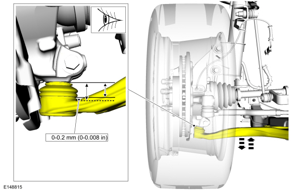
- To measure ball joint deflection, attach a suitable dial indicator with a flexible lever between the lower control arm and the steering knuckle or ball joint stud.
- Measure the ball joint deflection while an assistant manually pushes the lower control arm up and down.
- If the deflection exceeds the specification, install a new lower arm assembly.
REFER TO: Lower Arm (204-01 Front Suspension, Removal and Installation).
- If the deflection is within the specification, no further action is required.
- If the deflection exceeds the specification, install a new lower arm assembly.
Test yourself
A quick Ford Fiesta quiz: every answer comes with an explanation and a link to the manual page.