Steering Knuckle. Removal and Installation
Special Service Tools / General Equipment
 |
204-161 (T97P-1175-A) Installer, Axle Shaft TKIT-1997-LM2 TKIT-1997-F/FM2 TKIT-1997-FLM2 |
 |
205-D070 (D93P-1175-B) Remover, Front Wheel Hub Puller, Front Wheel Hub |
| Tie Rod End Remover | |
Removal
NOTICE: Suspension fasteners are critical parts that affect the performance of vital components and systems. Failure of these fasteners may result in major service expense. Use the same or equivalent parts if replacement is necessary. Do not use a replacement part of lesser quality or substitute design. Tighten fasteners as specified.
- Remove the wheel and tire.
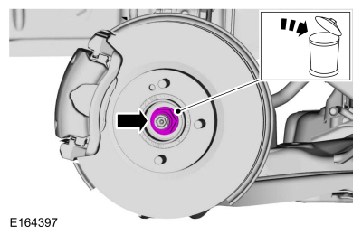
Refer to: Wheels and Tires (204-04A Wheels and Tires, Removal and Installation). - Remove and discard the wheel hub nut.
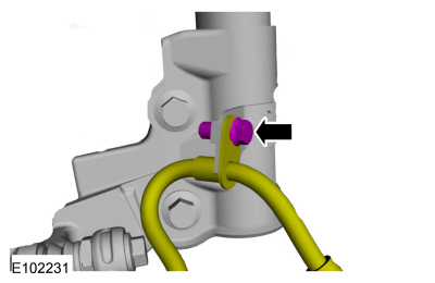
- Remove the brake hose bracket bolt and set the brake hose aside.
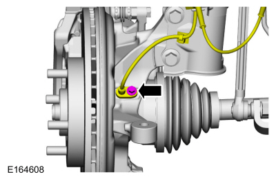
- Remove the bolt and set the wheel speed sensor aside.
NOTICE: Do not use a hammer to separate the outer tie rod end from the steering knuckle, otherwise damage to the steering knuckle may occur.
NOTICE: Use care when installing the tie rod separator, as damage to the outer tie rod end boot may occur.
Remove and discard the tie rod end nut and disconnect the tie rod end from the steering knuckle.
Use the general equipment: tie rod end remover.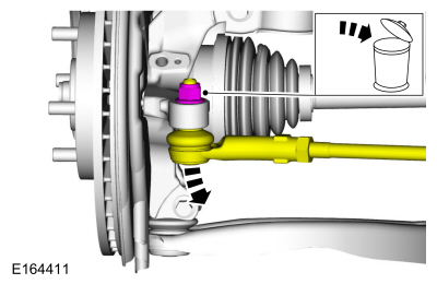
NOTICE: Do not use a pry bar or separator fork between the ball joint and steering knuckle. Damage to the ball joint or ball joint seal may occur. Use a pry bar only by inserting it into the lower arm housing hole.
NOTICE: Use care when releasing the lower control arm and rotating the steering knuckle to avoid damaging the ball joint seal.
Remove and discard the ball joint pinch bolt and nut and separate the lower arm from the steering knuckle.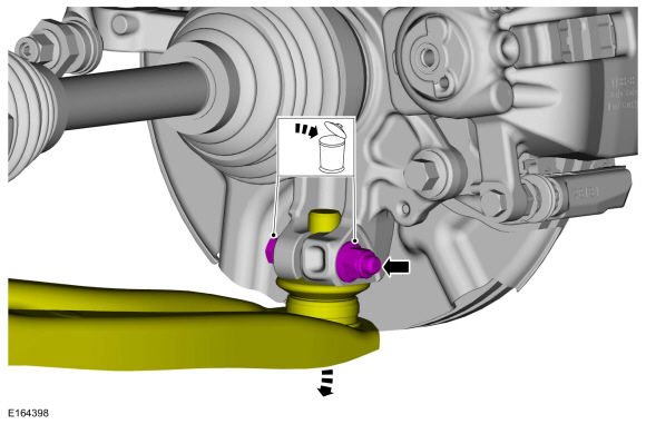
NOTICE: Do not bend the inboard joint more than 18 degrees or the outboard joint more than 45 degrees. Shaft damage will occur.
Using the special tool, press the axle shaft out of the wheel bearing and hub. Support the axle shaft in a horizontal position.
Use special service tool: 205-D070 (D93P-1175-B) Remover, Front Wheel Hub.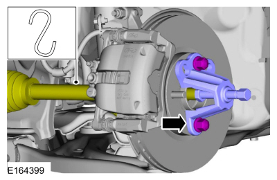
- Remove the brake rotor.
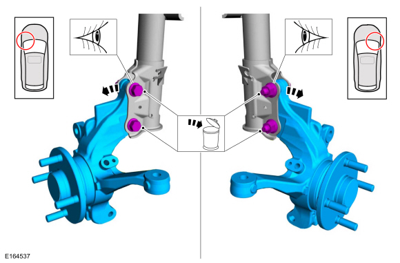
Refer to: Brake Rotor (206-03 Front Disc Brake, Removal and Installation). - Remove and discard the front strut and spring. Remove the steering knuckle bolts and nuts from the strut assembly and remove the steering knuckle.
Installation
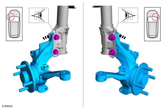
- Install the steering knuckle and install a new front strut and the spring-to-steering knuckle bolts and nuts.
- Install the brake rotor.
Refer to Brake Rotor (206-03 Front Disc Brake, Removal and Installation). - Using the special tools, install the axle shaft into the wheel bearing and hub.
Use the special service tool: 204-161 (T97P-1175-A) Installer, axle shaft.
- Attach the lower arm to the steering knuckle and install a new pinch bolt and ball joint nut.
Torque: 38 lb-ft (52 N·m)
- Connect the tie rod end to the steering knuckle and install a new tie rod end nut.
Torque: 39 lb-ft (53 N·m)
- Position the wheel speed sensor and install the bolt.
Torque: 80 lb-in (9 N·m) - Position the brake hose and install the brake hose bracket bolt.
Torque: 19 lb-ft (26 N·m) - Install the wheel hub nut.
Torque: 188 lb-ft (255 N·m)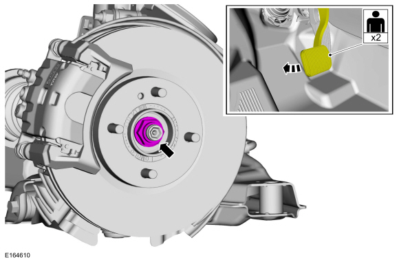
- Install the wheel and tire.
Refer to: Wheels and Tires (204-04A Wheels and Tires, Removal and Installation). - Check and adjust the front toe if necessary.
Refer to: Front Toe Adjustment (204-00 Suspension System - General Information, General Procedures).
Test yourself
A quick Ford Fiesta quiz: every answer comes with an explanation and a link to the manual page.