Front Stabilizer Bar - Removal and Installation
Special Service Tools / General Equipment
 |
300-OTC1585AE Powertrain Lift |
| Tie Rod End Remover | |
| Wood block | |
Removal
- Position the steering wheel in the straight-ahead position.

- If equipped.
Remove the tab and the bushing.
NOTICE: Do not allow the steering column to rotate while the steering column shaft is disconnected or the clockspring may be damaged. If there is any indication that the steering column shaft has rotated, remove and center the clockspring. For additional information, refer to Section 501-20B.
Remove and discard the steering column shaft bolt and disconnect the steering column shaft from the steering gear.
- Remove the wheel and tire.
Refer to: Wheels and Tires (204-04A Wheels and Tires, Removal and Installation). - Both sides.
Remove and discard the lower stabilizer bar link nuts and set the front stabilizer bar links aside.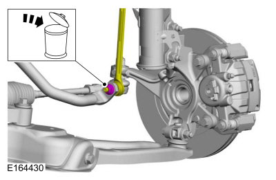
NOTICE: Do not use a hammer to separate the outer tie rod end from the steering knuckle, otherwise damage to the steering knuckle may occur.
NOTICE: Use care when installing the tie rod separator, as damage to the outer tie rod end boot may occur.
Both sides.
Remove and discard the tie rod end nut and separate the tie rod end from the steering knuckle.
Use common shop equipment: tie rod end remover.
- Remove the subframe brace-to-body bolts.

- Remove the engine roll restrictor bolt.

- Disconnect the exhaust isolator.

- Both sides.
Mark the position of the subframe-to-frame attachment at each mounting point on the vehicle frame rails to aid installation.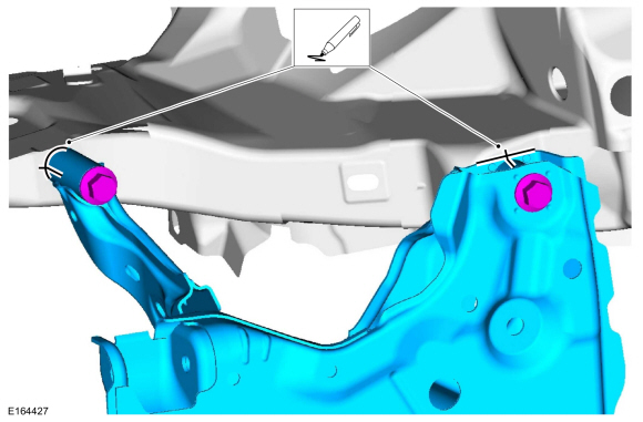
- Install the powertrain lift.
Use the special service tool: 300-OTC1585AE Powertrain Lift.
Use common shop equipment: wood block
- Remove the front front subframe bolts.
- Remove and discard the front subframe rear bolts.

- Lower the front subframe.
Use the special service tool: 300-OTC1585AE Powertrain Lift.
Use common shop equipment: wood block
Measurement: 5.906 in (150 mm)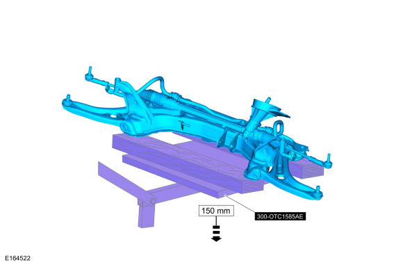
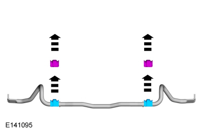
- Remove the front stabilizer bar bracket bolts and the front stabilizer bar.

- Replace the front stabilizer bar bushings.
Installation
NOTICE: The stabilizer bar bushings must be installed correctly, with the slit in the bushing facing the rear of the vehicle, or the bushings may be damaged.
Make sure these components are positioned as noted for removal. Install the front stabilizer bar bushing.
- Both sides.
Install the front stabilizer bar bushing bracket.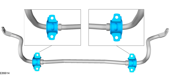
- Install the new front stabilizer bar bracket bolts.
Torque: 35 lb-ft (48 N·m) - Raise the subframe.
Use the special service tool: 300-OTC1585AE Powertrain Lift.
Use common shop equipment: wood block
Measurement: 5.906 in (150 mm)
- At this stage, tighten the bolts by hand only.
Loosely install the front subframe front bolts.
- At this stage, tighten the bolts by hand only.
Loosely tighten the new front subframe rear bolts.
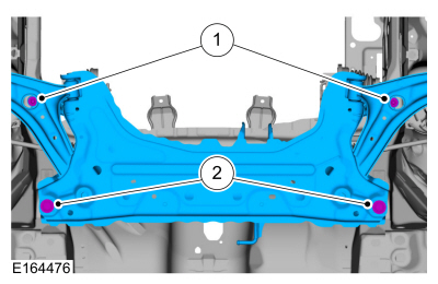
- At this stage, tighten the bolts by hand only.
- Both sides.
Align the subframe with the alignment marks made during removal.
Measure the correct position of the subframe relative to the vehicle underbody.- Location 1 -
Measurement: 10.236 in (260 mm)
- Location 2 -
Measurement: 26.220 in (666 mm)
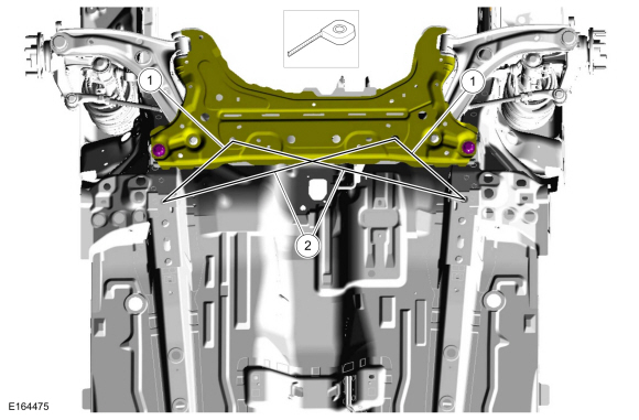
- Location 1 -
- Tighten the front subframe front bolts.
Torque: 44 lb-ft (60 N·m)
- Tighten the front subframe rear bolts.
Torque:
Stage 1: 74 lb-ft (100 N·m)
Stage 2: 240 degrees
- Tighten the front subframe front bolts.
- Install the subframe brace-to-body bolts.
Torque: 35 lb-ft (48 N·m) - Connect the exhaust isolator.
- Install the engine roll restrictor and install the engine roll restrictor bolt.
Torque: 37 lb-ft (50 N·m)
- Both sides.
Position the outer tie rods and install new outer tie rod nuts.
Torque: 39 lb-ft (53 N·m)
- Both sides.
Position the stabilizer bar links and install new stabilizer bar link-to-stabilizer bar nuts.
Torque: 35 lb-ft (48 N·m)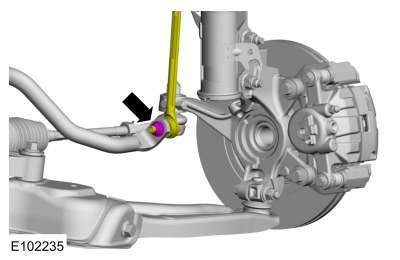
- Install the wheel and tire.
Refer to: Wheels and Tires (204-04A Wheels and Tires, Removal and Installation). - Connect the steering column shaft and install a new steering column shaft-to-steering gear bolt.
Torque: 25 lb-ft (34 N·m)
- If equipped.
Install the tab and the bushing. - Check and adjust the front toe if necessary.
Refer to: Front Toe Adjustment (204-00 Suspension System - General Information, General Procedures).
Test yourself
A quick Ford Fiesta quiz: every answer comes with an explanation and a link to the manual page.