Powertrain
Forward Clutch
In this manual: Powertrain
3steps
~28min
3/5difficulty
2special tools
Done 0 of 3
Special Tool(s)
Material
Disassembly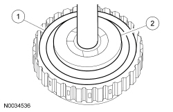
 Assembly
 |
Compressor, Spring Washer 307-209 |
 |
Dial Indicator Gauge With Holding Fixture 100-002 (TOOL-4201-C) |
Material
| Item | Specification |
|---|---|
| Motorcraft® MERCON® LV Automatic Transmission Fluid XT-10-QLVC (US); CXT-10-LV12 (Canada) | MERCON® LV |
| Item | Part Number | Description |
|---|---|---|
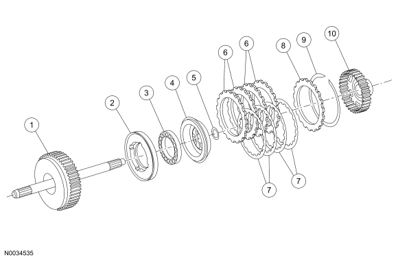
| 1 | 7F207 | Shaft assembly — turbine |
| 2 | 7A262 | Piston assembly — forward clutch |
| 3 | 7F235 | Spring assembly — forward piston return |
| 4 | 7H360 | Piston — forward clutch balance |
| 5 | 7H365 | Ring — forward clutch balance piston snap thrust bearing |
| 6 | 7B442 | Steel plates — forward clutch separator |
| 7 | 7B164 | Friction plate assembly — forward clutch |
| 8 | 7B066 | Plate — forward clutch pressure |
| 9 | 7D483 | Retaining ring |
| 10 | 7B067 | Hub — forward clutch cylinder |
Disassembly
- Remove the forward clutch pressure, friction and steel plates.
- Remove the retaining ring.
- Remove the plates.
- Using the Spring Washer Compressor, install the forward clutch assembly in a suitable press.
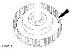
- Using the Spring Washer Compressor, remove the forward clutch balance piston snap ring.
- NOTICE: If damage to the forward clutch balance piston seals is found, install a new balance piston.
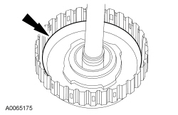
Remove and inspect the forward clutch balance piston.
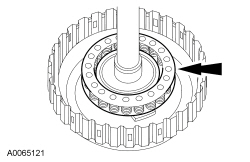
- Remove the forward piston return spring.
- NOTICE: If damage is found to the forward clutch piston seals, install a new forward clutch piston.
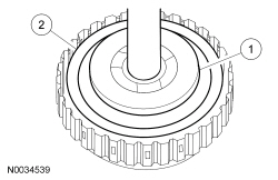
Remove the forward clutch piston assembly.
Assembly
- Soak the internal spline clutch plates in clean transmission fluid.
- Inspect the forward clutch piston bore surfaces for nicks or scratches. Install a new balance piston if necessary.
- Lubricate and install the forward clutch piston assembly.
- Install the forward piston return spring.
- Lubricate and install the forward clutch balance piston.
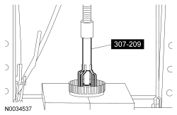
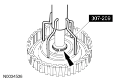
- Using the Spring Washer Compressor, install the forward clutch assembly in a suitable press.
- Using the Spring Washer Compressor, install the forward clutch balance piston snap ring.
- Install the forward clutch pressure, friction and steel plates.
- Install the plates.
- Install the retaining ring.
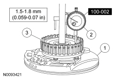
- Measure the clutch pack clearance.
- Install the forward clutch on the pump assembly.
- Install the Dial Indicator Gauge With Holding Fixture on the pump assembly and position the Dial Indicator plunger on the pressure plate.
- Using a suitable tool, lift up on both sides of the clutch pack and measure and record the clutch pack clearance on the Dial Indicator in 3 different areas. Average the measurements.
- Compare the forward clutch pack clearance to the specification (1.5-1.8 mm [0.059-0.07 in]). If the clutch pack clearance is not within specification, select and install the correct size retaining ring to obtain the specified clearance.
- 1.15-1.25 mm (0.045-0.049 in)
- 1.35-1.45 mm (0.053-0.057 in)
- 1.55-1.65 mm (0.061-0.064 in)
- 1.75-1.85 mm (0.068-0.072 in)
- 1.95-2.05 mm (0.076-0.080 in)
- 2.15-2.25 mm (0.084-0.088 in)
Test yourself
A quick Ford Focus quiz: every answer comes with an explanation and a link to the manual page.
Was this page helpful?