The diagnosis in this manual assumes a certain level of skill and knowledge of Ford-approved diagnostic procedures. REFER TO: Diagnostic Methods (100-00 General Information, Description and Operation).
Network Dtcs (U-codes) are often the result of intermittent concerns such as damaged wiring or low battery voltage. In addition, vehicle repair procedures such as module reprogramming often set network DTCs. Replacing a module to fix a network DTC is unlikely to solve the concern. To prevent recurrence of network DTC concerns, inspect all network wiring, especially the connectors. Check the vehicle battery. Refer to: Battery (414-01 Battery, Mounting and Cables, Diagnosis and Testing).
PCM DTC Chart
Trouble Code
Description
Action
P164D
AWD ID block is damaged or not programmed
PROGRAM the PCM with the Active Torque Coupling (ATC) solenoid barcode information using the Torque Coupling automatic configuration. Refer to: All Wheel Drive Systems - System Operation and Component Description (308-07A All Wheel Drive Systems, Description and Operation).
P181F
Clutch Control System Performance
This is an internal fault of the AWD relay module. INSTALL a new AWD relay module. Refer to: All Wheel Drive (AWD) Module (308-07A All Wheel Drive Systems, Removal and Installation).
P182B
Transfer Case Fluid Temperature Sensor Circuit Range/Performance
GO to Pinpoint Test F
P182C
Transfer Case Fluid Temperature Sensor Circuit Low
GO to Pinpoint Test F
P182D
Transfer Case Fluid Temperature Sensor Circuit High Signal Level
GO to Pinpoint Test F
P183D
Transfer Case Fluid Overtemperature
GO to Pinpoint Test F
P187B
Tire Size Out of Range - All Wheel Drive Disabled / Limited Function
GO to Pinpoint Test B
P188B
All Wheel Drive Clutch Control Circuit
GO to Pinpoint Test C
P188C
All Wheel Drive Relay Module Communication Circuit
CLEAR the DTCs. REPEAT the self-test. If the DTC returns, GO to Pinpoint Test D.
P188D
All Wheel Drive Relay Module Feedback Circuit
CLEAR the DTCs. REPEAT the self-test. If the DTC returns, GO to Pinpoint Test D.
Symptom Chart
The diagnosis in this manual assumes a certain level of skill and knowledge of Ford-approved diagnostic procedures. REFER TO: Diagnostic Methods (100-00 General Information, Description and Operation).
In most cases, the PCM sets DTCs to aid in diagnosis. Refer to the DTC Chart before using the symptom chart. The Symptom column lists the vehicle condition. The Possible Sources column lists the specific vehicle condition details. The Action column lists the actions to perform to determine the cause of the condition. Each action lists the components that may cause the system fault and individual components of that system. Components are listed in disassembly order. Use the component list and required actions to focus on disassembly checks for the root cause of the concern.
Symptom Chart - All Wheel Drive Systems
Condition
Possible Sources
Action
Unable to duplicate customer concern; no DTCs present
Concern description is inaccurate
PERFORM the All Wheel Drive system functional test. GO to Pinpoint Test A
Vehicle has no or insufficient torque at the rear wheels
Fuse
Wiring, Terminals or Connectors
Active Torque Coupling (ATC) solenoid
All-wheel drive relay module
PCM
GO to Pinpoint Test C
Wheels/Tires
Inspect the wheels and tires for damage. Refer to: Wheels and Tires (204-04A Wheels and Tires, Diagnosis and Testing).
Rear Axle
Inspect the rear axle for damage. Refer to: Rear Axle and Differential (205-02 Rear Axle/Differential, Diagnosis and Testing).
PTU mechanical fault
Inspect the PTU for damage. Refer to: Rear Axle and Differential (205-02 Rear Axle/Differential, Diagnosis and Testing).
Vehicle binds in turns or resists turning/shudders or jerks in a straight line
Wheels/Tires
Inspect the wheels and tires for damage. Refer to: Wheels and Tires (204-04A Wheels and Tires, Diagnosis and Testing).
Wiring, Terminals or Connectors
GO to Pinpoint Test E
Driveshaft
Inspect the propshaft for damage. Refer to: Propshaft (205-01 Propshaft, Diagnosis and Testing).
Wiring, Terminals or Connectors
Active Torque Coupling (ATC) solenoid
All-wheel drive relay module
GO to Pinpoint Test E
PTU mechanical fault
Inspect the PTU for damage. Refer to: Power Transfer Unit (308-07B Power Transfer Unit - 6-Speed Automatic Transmission - 6F35, Diagnosis and Testing). Refer to: Power Transfer Unit (308-07C Power Transfer Unit - 6-Speed Automatic Transmission - 6F50/6F55, Diagnosis and Testing).
Driveshaft
Inspect the propshaft for damage. Refer to: Suspension System (204-00 Suspension System - General Information, Diagnosis and Testing).
Wheel bearings
Inspect the wheel bearings for damage. Refer to: Suspension System (204-00 Suspension System - General Information, Diagnosis and Testing).
ABS
INSPECT the ABS. Refer to: Anti-Lock Brake System (ABS) and Stability Control System (206-09 Anti-Lock Brake System (ABS) and Stability Control System, Diagnosis and Testing).
Half Shafts
Inspect the half shafts for damage. Refer to: Rear Drive Half Shafts (205-05 Rear Drive Half Shafts, Diagnosis and Testing).
Tire/axle out of tolerance
Wheels/Tires
GO to Pinpoint Test B
Pinpoint Tests
All Wheel Drive System Functional Test
Normal Operation and Fault Symptoms
The all-wheel drive system is an active system, which means that it not only reacts to wheel slip between the front and rear axles, but also has the ability to anticipate wheel slip and transfer torque to the rear wheels before slipping occurs. The all-wheel drive system is active at all times and does not require operator input. The all-wheel drive system constantly monitors vehicle conditions and automatically adjusts torque distribution between the front and rear wheels. During normal operation, most of the torque is delivered to the front wheels. If wheel slip is detected between the front and rear wheels, if the vehicle is accelerating, or if the vehicle is being steered, the all-wheel drive system increases and distributes torque to the rear wheels as needed. When the all-wheel drive system is operating normally, there should be no noticeable speed difference between the front and rear axles when starting or driving the vehicle on any level surface. Traction should be similar to a part-time 4WD system in 4H (4X4 HIGH), but without binding in turns .
AWD_CLTCH_CMD PID percentage displayed on the scan tool is an inverse value. 95% = clutch released, 5% = clutch fully engaged.
Visual Inspection and Preliminary Diagnosis
ABS Sensor Wiring
Constant Velocity (CV) Joints
Driveshaft
Half Shafts
Tire Size
Tire Wear
U-Joints
PINPOINT TEST A: AWD (ALL WHEEL DRIVE) SYSTEM FUNCTIONAL TEST
WARNING: When this test calls for driving the vehicle, drive the vehicle on a firm surface in an area free of traffic to prevent an accident. Failure to follow these instructions may result in personal injury.
NOTE: Check the applicable modules for diagnostic trouble codes (DTCs). If DTCs are set in other modules, diagnose these DTCs before continuing.
A1 CHECK THE ACTIVE TORQUE COUPLING ELECTROMAGNETIC CLUTCH
Drive the vehicle on a dry, firm surface while applying the accelerator pedal.
Is there transmission binding in turns?
Yes
GO to Pinpoint Test E
No
GO to A2
A2 CHECK THE ABS WHEEL SPEED
Using a scan tool, drive the vehicle at 30 mph (48 km/h) and monitor the following wheel speed sensor PIDs:
Left Front Wheel Speed Sensor (LF_WSPD)
Left Rear Wheel Speed Sensor (LR_WSPD)
Right Front Wheel Speed Sensor (RF_WSPD)
Right Rear Wheel Speed Sensor (RR_WSPD)
Are all 4 wheel speeds within 1.2 mph (2 km/h) of each other?
Yes
GO to A3
No
REFER TO: Anti-Lock Brake System (ABS) and Stability Control System (206-09 Anti-Lock Brake System (ABS) and Stability Control System, Diagnosis and Testing).
A3 CHECK VEHICLE ACCELERATION IN A STRAIGHT LINE
Perform 3 accelerations from 0 mph (0 km/h) to 30 mph (48 km/h) in a straight line (one each with light, medium, and full accelerator pedal application).
Does the vehicle pulsate or jerk during acceleration?
Yes
GO to Pinpoint Test E
No
GO to A4
A4 CHECK VEHICLE TURNING ABILITY
Drive the vehicle in a fully locked turn, on dry asphalt, at 5 mph (8 km/h).
Does the vehicle bind or resist turning?
Yes
GO to Pinpoint Test E
No
GO to A5
A5 CHECK REAR WHEEL TORQUE
Using the diagnostic scan tool, apply a constant 10% duty cycle to the active torque coupling (ATC) solenoid.
On dry asphalt, drive the vehicle in a fully locked turn at 5 mph (8 km/h).
Does the vehicle bind or resist turning?
Yes
EXIT the active command. CLEAR all DTCs, if set. End of the system functional test. The system is currently operating correctly.
No
CHECK the power transfer unit (PTU). REFER TO: Power Transfer Unit (308-07B Power Transfer Unit - 6-Speed Automatic Transmission - 6F35, Diagnosis and Testing). REFER TO: Power Transfer Unit (308-07C Power Transfer Unit - 6-Speed Automatic Transmission - 6F50/6F55, Diagnosis and Testing).
DTC P187B
Normal Operation and Fault Symptoms
The all-wheel drive system uses input from the ABS module wheel speed sensors as an input to the PCM. A spare tire of a different size (other than the provided spare tire), or large unequal tire sizes or incorrectly inflated tires between the front and rear axles may cause the all-wheel drive system to not function properly.
DTC Fault Trigger Conditions
Trouble Code
Description
Fault Trigger Conditions
P187B
Tire Size Out of Acceptable Range - All-Wheel Drive Disabled/Limited Function
When the PCM detects tires/wheels of improper size (more than 5% difference in size between the front and rear axles, or more than 14% difference in size on one wheel on the front or rear axle).
Possible Causes
Wiring, Terminals or Connectors
Wheels/Tires
ABS system
Visual Inspection and Preliminary Diagnosis
Check the tire size and inflation.
PINPOINT TEST B: DTC P187B
B1 CHECK FOR RECENT USE OF DIFFERENT SIZE TIRES
Ask the customer about recent tire replacements or installations.
Was a tire recently installed on the vehicle that did not originally come with the vehicle, or was a temporary spare tire used?
Yes
The concern may have been caused by previously mismatched tires. ENSURE that the tires do not exceed original equipment manufacturer (OEM) sizes and that all 4 tires are the same size.
No
GO to B2
B2 CHECK TIRE SIZE AND BRAND
Check the tire size and brand.
Are all 4 tires the same size and brand?
Yes
GO to B3
No
The tire size must not exceed original equipment manufacturer (OEM) recommendations, and all 4 tires must be the same size and brand. INSTALL new tire(s) as necessary.
B3 CHECK TIRE AIR PRESSURE
Check the air pressure in all 4 tires.
Is the air pressure in all 4 tires within specification?
Yes
GO to B4
No
ADJUST the tire air pressure to specification.
B4 CHECK ABS WHEEL SPEED
Drive the vehicle at 30 mph (48 km/h) and monitor the following wheel speed sensor PIDs:
Left Front Wheel Speed Sensor (LF_WSPD)
Left Rear Wheel Speed Sensor (LR_WSPD)
Right Front Wheel Speed Sensor (RF_WSPD)
Right Rear Wheel Speed Sensor (RR_WSPD)
Are all 4 wheel speeds within 1.2 mph (2 km/h) of each other?
Yes
GO to B5
No
The ABS module is sending incorrect wheel speed data to the PCM. REFER TO: Anti-Lock Brake System (ABS) and Stability Control System (206-09 Anti-Lock Brake System (ABS) and Stability Control System, Diagnosis and Testing).
B5 CHECK ABS AND AWD (ALL-WHEEL DRIVE) SYSTEM OPERATION
Ignition OFF.
Disconnect the ABS, all-wheel drive relay module and active torque coupling (ATC) solenoid connectors.
Check the following:
corrosion (install new connector or terminals - clean module pins)
damaged or bent pins - install new terminals/pins
backed-out pins - install new pins as necessary
Reconnect the ABS, all-wheel drive relay module and active torque coupling (ATC) solenoid connectors. Make sure they are fully seated and locked.
Operate the system and determine if the concern is still present.
Is the concern still present?
Yes
CHECK OASIS for applicable TSBs. If a TSB exists for this concern, STOP this test and FOLLOW the TSB instructions. If no TSB resolves this concern, Click here to access the Managed Routine (ABS). Internet Explorer version 11 or later is required to perform this Pinpoint test.
No
The system is currently operating correctly. The concern may have been caused by module connections. Refer to the root cause of any connector or terminal issues.
DTC P188B
For wiring diagrams and connector information, refer to Section 34 of the wiring diagrams.
Normal Operation and Fault Symptoms
The all-wheel drive system uses data from other systems as inputs to the PCM. The PCM uses these inputs to determine the appropriate time to send a signal and energize the all-wheel drive relay module to the active torque coupling (ATC) solenoid.
AWD_CLTCH_CMD PID percentage displayed on the scan tool is an inverse value. 95% = clutch released, 5% = clutch fully engaged.
DTC Fault Trigger Conditions
Trouble Code
Description
Fault Trigger Conditions
P188B
All Wheel Drive Clutch Control Circuit
When the PCM detects an open circuit, a short to ground or a voltage in the active torque coupling (ATC) solenoid supply and/or return circuit.
Possible Causes
Wiring, Terminals or Connectors
Active torque coupling (ATC) solenoid (part of the rear drive unit (RDU))
All-wheel drive relay module
PCM
Visual Inspection and Preliminary Diagnosis
Active torque coupling (ATC) solenoid harness
PINPOINT TEST C: P188B
C1 CHECK THE ACTIVE TORQUE COUPLING SOLENOID
Ignition OFF.
Disconnect the active torque coupling (ATC) solenoid C4347.
Action:
Positive lead
Measurement/Action
Negative lead
C4347-1
C4347-2
Is the resistance between 1 and 3 ohms?
Yes
GO to C2
No
INSTALL a new active torque coupling. REFER TO: Active Torque Coupling (205-02 Rear Axle/Differential, Removal and Installation).
C2 CHECK THE ACTIVE TORQUE COUPLING SOLENOID CIRCUITS FOR A SHORT TO VOLTAGE
Disconnect the all-wheel drive relay module C4379.
The ignition is on.
Action: Click to display the connectors
Positive lead
Measurement/Action
Negative lead
C4379-5
Ground
C4379-8
Ground
Is there voltage present?
Yes
REPAIR the circuit.
No
GO to C3
C3 CHECK THE ACTIVE TORQUE COUPLING SOLENOID CIRCUITS FOR A SHORT TO GROUND
Action: Click to display the connectors
Positive lead
Measurement/Action
Negative lead
C4379-5
Ground
C4379-8
Ground
Is the resistance greater than 10000 Ohms?
Yes
GO TO C4
No
REPAIR the circuit.
C4 CHECK THE ACTIVE TORQUE COUPLING SOLENOID CIRCUITS FOR AN OPEN CIRCUIT
Action: Click to display the connectors
Positive lead
Measurement/Action
Negative lead
C4379-5
C4347-1
C4379-8
C4347-2
Is the resistance less than 3 ohms?
Yes
GO to C5
No
REPAIR the open circuit.
C5 CHECK THE ACTIVE TORQUE COUPLING SOLENOID CIRCUITS FOR A SHORT CIRCUIT TOGETHER
Action: Click to display the connectors
Positive lead
Measurement/Action
Negative lead
C4379-5
C4379-8
Is the resistance greater than 10000 Ohms?
Yes
GO to C6
No
REPAIR the circuits.
C6 CHECK THE PCM (POWERTRAIN CONTROL MODULE) OPERATION
Ignition OFF.
Disconnect all PCM connectors.
Repair:
corrosion (install new connector or terminals - clean module pins)
damaged or bent pins - install new terminals/pins
backed-out pins - install new pins as necessary
Reconnect all PCM, all-wheel drive relay module and active torque coupling (ATC) solenoid connectors. Make sure they are fully seated and locked.
PERFORM the all-wheel drive cycle. REFER TO: All-Wheel Drive (AWD) Systems (308-07A). and determine if the concern remains.
Is the concern still present?
Yes
CHECK OASIS for applicable TSBs. If a TSB exists for this concern, STOP this test and FOLLOW the TSB instructions. If no TSB addresses this concern, INSTALL a new all-wheel drive relay module. REFER TO: All-Wheel Drive Module — 2 L Duratorq-TDCi (110 kW/150 L PS) (308-07A). CLEAR the DTCs. PERFORM the all-wheel drive cycle, REFER TO: All-Wheel Drive (AWD) Systems (308-07A). If the DTC returns, Click here to access the guided routine (PCM). Internet Explorer version 11 or later is required to perform this Pinpoint test.
No
The system is currently operating correctly. The concern may have been caused by module connections. ADDRESS the root cause of any connector or terminal issues.
DTCs P188C, P188D
For wiring diagrams and connector information, refer to Section 34 of the wiring diagrams.
Normal Operation and Fault Symptoms
The all-wheel drive system uses data from other systems as inputs to the PCM. The PCM uses these inputs to determine the appropriate time to send a signal and energize the all-wheel drive relay module to the active torque coupling (ATC) solenoid.
DTC Fault Trigger Conditions
Trouble Code
Description
Fault Trigger Conditions
P188C
All Wheel Drive Relay Module Communication Circuit
When the PCM detects an open circuit, a short to ground or a voltage in the control circuit.
P188D
All Wheel Drive Relay Module Feedback Circuit
When the PCM detects an open circuit, a short to ground or a voltage in the feedback circuit.
Possible Causes
Wiring, Terminals or Connectors
All-wheel drive relay module
PCM
Visual Inspection and Preliminary Diagnosis
BJB fuse 12 (15A)
PINPOINT TEST D: AWD (ALL WHEEL DRIVE) SIGNAL CIRCUIT FAULT
D1 CHECK THE ALL-WHEEL DRIVE (AWD) RELAY VOLTAGE CIRCUIT
Ignition OFF.
Disconnect the all-wheel drive relay module C4379.
Inspect the connectors for damage or terminal pushout, corrosion, loose wires, and missing or damaged seals.
The ignition is on.
Action:
Positive lead
Measurement/Action
Negative lead
C4379-1
Ground
Is the voltage greater than 11 volts?
Yes
GO to D2
No
CHECK that BJB fuse 12 (15A) is good. If good, REPAIR the open circuit. If not good, CONSULT the wiring diagrams to determine the possible causes of the short circuit. CLEAR the DTCs.
D2 CHECK THE ALL-WHEEL DRIVE (AWD) RELAY MODULE GROUND CIRCUIT FOR AN OPEN CIRCUIT
Action: Click to display the connectors
Positive lead
Measurement/Action
Negative lead
C4379-1
C4379-4
Is the voltage greater than 11 volts?
Yes
GO to D3
No
REPAIR the circuit.
D3 CHECK THE ALL-WHEEL DRIVE (AWD) RELAY MODULE CONTROL AND FEEDBACK CIRCUITS FOR A SHORT TO VOLTAGE
The ignition is on.
Action: Click to display the connectors
Positive lead
Measurement/Action
Negative lead
C4379-1
C4379-4
Is there voltage present?
Yes
GO to D4
No
REPAIR the circuit.
D4 CHECK THE ALL-WHEEL DRIVE (AWD) RELAY MODULE CONTROL AND FEEDBACK CIRCUITS FOR A SHORT TO GROUND
Action: Click to display the connectors
Positive lead
Measurement/Action
Negative lead
C4379-6
Ground
C4379-3
Ground
Is the resistance greater than 10000 Ohms?
Yes
GO to D5
No
REPAIR the circuit.
D5 CHECK THE ALL-WHEEL DRIVE (AWD) RELAY MODULE CONTROL AND FEEDBACK CIRCUITS FOR AN OPEN CIRCUIT
Disconnect PCM 1.5 L C1915B.
Disconnect PCM 2 L C1381B.
Disconnect PCM 2.5 L C1551B.
Disconnect PCM 2.7 L C1231B.
Action: Click to display the connectors
For 1.5 L
Positive lead
Measurement/Action
Negative lead
C4379-6
C1915B-46
C4379-3
C1915B-60
Click to display the connectors
For 2 L
Positive lead
Measurement/Action
Negative lead
C4379-6
C1381B-46
C4379-3
C1381B-60
Click to display the connectors
For 2.5 L
Positive lead
Measurement/Action
Negative lead
C4379-6
C1551B-46
C4379-3
C1551B-60
Click to display the connectors
For 2.7 L
Positive lead
Measurement/Action
Negative lead
C4379-6
C1231B-46
C4379-3
C1231B-60
Is the resistance less than 3 ohms?
Yes
GO to D6
No
REPAIR the circuit.
D6 CHECK THE ALL-WHEEL DRIVE (AWD) RELAY MODULE CONTROL AND FEEDBACK CIRCUITS FOR A SHORT CIRCUIT TOGETHER
Action. Click to display connectors
Positive lead
Measurement/Action
Negative lead
C4379-6
C4379-3
Is the resistance greater than 10000 Ohms?
Yes
GO to D3
No
CHECK OASIS for applicable TSBs. If a TSB exists for this concern, STOP this test and FOLLOW the TSB instructions. If no TSB resolves this concern, Click here to access the guided routine (PCM). Internet Explorer version 11 or later is required to perform this Pinpoint test.
D7 CHECK THE PCM (POWERTRAIN CONTROL MODULE) FOR PROPER OPERATION
Ignition OFF.
Disconnect all PCM connectors.
Check the following:
corrosion (install new connector or terminals - clean module pins)
damaged or bent pins - install new terminals/pins
backed-out pins - install new pins as necessary
Connect all PCM connectors. Make sure they are fully seated and locked.
PERFORM the all-wheel drive cycle. REFER TO: All-Wheel Drive Systems — Operation and Component Description (308-07A All-Wheel Drive Systems, Description and Operation). and determine if the concern remains.
Is the concern still present?
Yes
CHECK OASIS for applicable TSBs. If a TSB exists for this concern, STOP this test and FOLLOW the TSB instructions. If no TSB resolves this concern, Click here to access the guided routine (PCM). Internet Explorer version 11 or later is required to perform this Pinpoint test.
No
The system is currently operating correctly. The concern may have been caused by a loose or corroded connector. ADDRESS the root cause of any connector or pin issues.
Vehicle binds in turns or resists steering/surges or jerks on straight-line driving
For wiring diagrams and connector information, refer to Section 34 of the wiring diagrams.
Normal Operation and Fault Symptoms
The all-wheel drive system is an active system, meaning it not only reacts to wheel slip between the front and rear axles, but also has the ability to anticipate wheel slip and transfer torque to the rear wheels before slip occurs. The all-wheel drive system is active at all times and requires no operator input. The all-wheel drive system continuously monitors vehicle conditions and automatically adjusts torque distribution between the front and rear wheels. During normal operation, most of the torque is sent to the front wheels. If wheel slip is detected between the front and rear wheels, if the vehicle is accelerating, or if the vehicle is being steered, the all-wheel drive system increases and distributes torque to the rear wheels as needed. When the all-wheel drive system is operating normally, there should be no noticeable speed difference between the front and rear axles when starting or driving on any level surface. Traction should be similar to a part-time 4WD system in 4H (4X4 HIGH), but without binding in turns.
AWD_CLTCH_CMD PID percentage displayed on the scan tool is an inverse value. 95% = clutch released, 5% = clutch fully engaged.
Possible Causes
Wiring, Terminals and Connectors
Wheels/Tires
ABS system
All-wheel drive relay module
Active Torque Coupling (ATC) Clutch
Visual Inspection and Preliminary Diagnosis
Wheel Speed Sensor Wiring Harness
PINPOINT TEST E: VEHICLE DRAGS OR RESISTS TURNING/SHUDDERS OR JERKS IN A STRAIGHT LINE
E1 CHECK REAR WHEEL TORQUE
Ignition OFF.
Disconnect the active torque coupling (ATC) solenoid C4347.
Inspect the connector for damage or spread terminals, corrosion, loose wires, and missing or damaged seals.
Drive the vehicle straight on a dry paved road.
Is the shudder or vibration still present?
Yes
REFER TO: Rear Axle and Differential (205-02 Rear Axle/Differential, Diagnosis and Testing).
No
GO to E2
E2 CHECK PTU CLUTCH CONTROL PID
Ignition OFF.
Connect the Active Torque Coupling (ATC) solenoid C4347.
The ignition is on.
Using the diagnostic scan tool, monitor the AWD_CLTCH_CMD# PID.
Drive the vehicle at a steady 5 mph (8 km/h) through tight turns on a dry paved road while monitoring the Active Torque Coupling (ATC) solenoid duty cycle.
Is the duty cycle less than 80%?
Yes
GO to E3
No
GO to Pinpoint Test B
E3 CHECK WHEEL SPEED CORRECTLY
Drive the vehicle at 30 mph (48 km/h) and monitor the following wheel speed sensor PIDs:
Left Front Wheel Speed Sensor (LF_WSPD)
Left Rear Wheel Speed Sensor (LR_WSPD)
Right Front Wheel Speed Sensor (RF_WSPD)
Right Rear Wheel Speed Sensor (RR_WSPD)
Are all 4 wheel speeds within 1.2 mph (2 km/h) of each other?
Disconnect the all-wheel drive relay module C4379.
Disconnect the active torque coupling (ATC) solenoid C4347.
Check the following:
corrosion (install new connector or terminals - clean module pins)
damaged or bent pins - install new terminals/pins
backed-out pins - install new pins as necessary
Connect the All-Wheel Drive (AWD) Relay Module C4379.
Connect the Active Torque Coupling (ATC) solenoid C4347 and make sure it is installed correctly.
PERFORM the all-wheel drive cycle. REFER TO: All-Wheel Drive Systems — Operation and Component Description (308-07A All-Wheel Drive Systems, Description and Operation). and determine if the concern remains.
Is the concern still present?
Yes
INSTALL a new All-Wheel Drive (AWD) relay module. REFER TO: All-Wheel Drive (AWD) Module (308-07A All-Wheel Drive Systems, Removal and Installation).
No
The system is currently operating correctly. The concern may have been caused by a loose or corroded connector. ADDRESS the root cause of any connector or pin issues.
P182B, P182K, P182D, P183D
For wiring diagrams and connector information, refer to Section 34 of the wiring diagrams.
Normal Operation and Fault Symptoms
The Power Transfer Unit (PTU) Fluid Temperature Sensor is located in the Power Transfer Unit (PTU) (6F50/55 only). It is a temperature-sensitive device called a thermistor. The sensor resistance value changes with temperature. The PCM monitors the voltage at the PTU fluid temperature sensor to determine the Power Transfer Unit (PTU) fluid temperature.
AWD_CLTCH_CMD PID percentage displayed on the scan tool is an inverse value. 95% = clutch released, 5% = clutch fully engaged.
DTC Fault Trigger Conditions
Trouble Code
Description
Fault Trigger Conditions
P182B
Transfer Case Fluid Temperature Sensor Circuit Range/Performance
This DTC sets when the PCM detects an open, short to ground or a voltage present in the sensor circuit.
P182C
Transfer Case Fluid Temperature Sensor Circuit Low
This DTC sets when the PCM detects a short to ground, open or low voltage in the sensor circuit.
P182D
Transfer Case Fluid Temperature Sensor Circuit High Signal Level
This DTC sets when the PCM detects a high voltage in the sensor circuit.
P183D
Transfer Case Fluid Overtemperature
This DTC sets in the PCM when the PTU fluid temperature exceeds the maximum operating temperature.
Possible Causes
Wiring, Terminals and Connectors
Power Transfer Unit (PTU) Fluid Temperature Sensor
PCM
Visual Inspection and Preliminary Diagnosis
Power Transfer Unit (PTU) Fluid Temperature Sensor Wiring Harness
PTU operation is normal and quiet
PTU fluid level
PINPOINT TEST F: P182B, P182C, P182D, P183D
F1 RETRIEVE AND RECORD ALL DTCS
Using the diagnostic scan tool, retrieve all DTCs.
Is DTC P182B, P182C, P182D and/or P183D present?
Yes
For DTCs P182B, P182C, P182D GO to F2. For DTC P183D ONLY GO to F6.
No
The system is now operating correctly. Confirm that the power transfer unit is not overheating due to a mechanical concern. REFER TO: Power Transfer Unit (308-07C Power Transfer Unit - 6-Speed Automatic Transmission - 6F50/6F55, Diagnosis and Testing).
F2 CHECK THE PTU FLUID TEMPERATURE SENSOR SIGNAL VOLTAGE
Ignition OFF.
Disconnect the PTU C1831.
Inspect the connector for damage or spread terminals, corrosion, loose wires, and missing or damaged seals.
The ignition is on.
Action: Click to display the connectors
Positive lead
Measurement/Action
Negative lead
C1831-1
Ground
Is the voltage greater than 4.1 volts?
Yes
GO to F3
No
GO to F4
F3 CHECK THE PTU FLUID TEMPERATURE SENSOR GROUND CIRCUIT FOR AN OPEN
Action: Click to display the connectors
Positive lead
Measurement/Action
Negative lead
C1831-1
C1831-2
Is the voltage greater than 4.1 volts?
Yes
GO to F5
No
REPAIR the circuit.
F4 CHECK THE PTU FLUID TEMPERATURE SENSOR SIGNAL CIRCUIT FOR AN OPEN
Ignition OFF.
Disconnect the PCM C1231B.
Engine 2.7 L, measure: Click to display connectors
Positive lead
Measurement/Action
Negative lead
C1831-1
C1231B-76
Is the resistance less than 3 ohms?
Yes
GO to F5
No
REPAIR the circuit.
F5 CHECK THE PTU FLUID TEMPERATURE SENSOR SIGNAL CIRCUIT FOR A SHORT TO GROUND
Action: Click to display the connectors
Positive lead
Measurement/Action
Negative lead
C1831-1
Ground
Is the resistance greater than 10000 Ohms?
Yes
GO to F6
No
REPAIR the circuit.
F6 CHECK THE PTU FLUID TEMPERATURE SENSOR RESISTANCE
Action:
Positive lead
Measurement/Action
Negative lead
PTU fluid temperature sensor component side, pin 1
PTU fluid temperature sensor component side, pin 2
Temperature C
Temperature F
MIN Ohms
MAX Ohms
MIN Volts
MAX Volts
-40
-40
2.541 M
4.545 M
4,96
4,98
-30
-22
1.367 M
2.337 M
4,93
4,96
-20
-4
766K
1.255 M
4,87
4,92
-10
14
444.9K
701.4K
4,78
4,86
0
32
267.1K
406.2K
4,65
4,77
10
50
164K
241.2K
4,46
4,62
20
68
103.6K
147.8K
4.19
4.40
25
77
83.21K
116.9K
4.03
4,27
30
86
67.23K
116.9K
3,85
4.12
40
104
44.67K
93.12k
3,45
3,75
50
122
30.35K
60.22K
3.01
3,33
60
140
21.04K
39.88K
2,56
2,87
70
158
14.86K
26.99K
2.13
2.14
80
176
10.68K
18.64K
1,74
1,98
90
194
7.79K
13.11K
1,40
1,60
100
210
5781
93.85K
1.12
1,27
110
230
4345
5038
0,89
1.01
120
248
3308
3771
0,71
0,79
130
266
2549
2859
0,57
0,63
140
284
1987
2194
0,45
0,49
150
302
1565
1703
0,36
0,39
Does the resistance match the temperature specification?
Yes
Click here to access the guided routine (PCM). Internet Explorer version 11 or later is required to perform this Pinpoint test.
No
INSTALL a new Power Transfer Unit (PTU) fluid temperature sensor.
?
Test yourself
A quick Ford Fusion quiz: every answer comes with an explanation and a link to the manual page.
 WARNING: When this test calls for driving the vehicle, drive the vehicle on a firm surface in an area free of traffic to prevent an accident. Failure to follow these instructions may result in personal injury.
 Click here to access the Managed Routine (ABS).
 Internet Explorer version 11 or later is required to perform this Pinpoint test.
 C4347-1

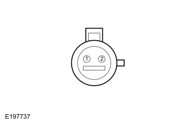 C4347-2


 Click here to access the guided routine (PCM).
 Internet Explorer version 11 or later is required to perform this Pinpoint test.


 Click here to access the guided routine (PCM).
 Internet Explorer version 11 or later is required to perform this Pinpoint test.
 Click here to access the guided routine (PCM).
 Internet Explorer version 11 or later is required to perform this Pinpoint test.


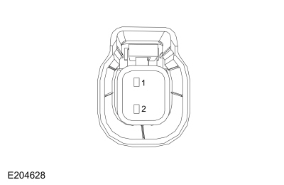 PTU fluid temperature sensor component side, pin 1

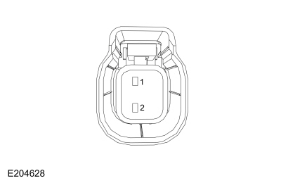 PTU fluid temperature sensor component side, pin 2
 Click here to access the guided routine (PCM).
 Internet Explorer version 11 or later is required to perform this Pinpoint test.