Locks, Latches and Entry Systems: Diagnosis and Testing
In this manual: Body and Paint
~152min read
1special tools
Diagnostic Trouble Code Charts
The diagnosis in this manual assumes a certain level of skill and knowledge of Ford-approved diagnostic procedures. REFER TO: Diagnostic Methods (100-00 General Information, Description and Operation).
DTC Chart
Trouble Code
Description
Action
B10AB:00
Remote Keyless Entry Synchronization: No Sub Type Information
GO to Pinpoint Test U
B10C7:01
Interior Trunk Antenna: General Electrical Failure
GO to Pinpoint Test Z
B11C6:01
Passenger Door Exterior Antenna: General Electrical Malfunction
GO to Pinpoint Test Y
B11KA:01
Driver Door Exterior Antenna: General Electrical Malfunction
GO to Pinpoint Test Y
B1218:00
Transmitter Identification Code: No Sub Type Information
GO to Pinpoint Test U
B1219:11
Interior Liftgate/Tailgate Open Switch: Short to Ground
GO to Pinpoint Test N
B121A: 11
Keypad Backlight Output: Short to Ground
GO to Pinpoint Test S
B121A: 15
Keypad Backlight Output: Short to Battery or Open Circuit
If the keypad backlight does not work, GO to Pinpoint Test S.
If the keypad backlight is always on, GO to Pinpoint Test T.
B121B: 01
Keypad Entry Switch: General Electrical Failure
GO TO Pinpoint Test R
B126A: 01
Driver Door Interior Lock Switch: General Electrical Failure
If the concern occurs when using the front door lock control switch, GO to Pinpoint Test J.
If the concern occurs when using the rear door lock control switch, GO to Pinpoint Test K.
B12EE:11
Liftgate/Tailgate/Trunk Unlock: Short to Ground
GO to Pinpoint Test N
B12EE:15
Liftgate/Tailgate/Trunk Lock: Short to Battery or Open Circuit
GO to Pinpoint Test N
B1381:11
Left Front Door Handle Proximity Sensor: Short to Ground
GO to Pinpoint Test Y
B1381:15
Left Front Door Handle Proximity Sensor: Short to Battery or Open
GO to Pinpoint Test Y
B1381:29
Left Front Door Handle Proximity Sensor: Incorrect Signal
GO to Pinpoint Test Y
B1382:11
Right Front Door Handle Proximity Sensor: Short to Ground
GO to Pinpoint Test Y
B1382:15
Right Front Door Handle Proximity Sensor: Short to Battery or Open
GO to Pinpoint Test Y
B1382:29
Right Front Door Handle Proximity Sensor: Invalid Signal
GO to Pinpoint Test Y
B1383:11
Left Rear Door Handle Proximity Sensor: Short to Ground
GO to Pinpoint Test Y
B1383:15
Left Rear Door Handle Proximity Sensor: Short to Battery or Open Circuit
GO to Pinpoint Test Y
B1383:29
Left Rear Door Handle Proximity Sensor: Invalid Signal
GO to Pinpoint Test Y
B1384:11
Right Rear Door Handle Proximity Sensor: Short to Ground
GO to Pinpoint Test Y
B1384:15
Right Rear Door Handle Proximity Sensor: Short to Battery or Open Circuit
GO to Pinpoint Test Y
B1384:29
Right Rear Door Handle Proximity Sensor: Invalid Signal
GO to Pinpoint Test Y
B1490:11
Lock Indicator LED Status Output: Short to Ground
GO to Pinpoint Test L
B1490:15
Lock Indicator LED Status Output: Short to Battery or Open Circuit
If the door lock indicator does not work, GO to Pinpoint Test L.
If the door lock indicator is always on, GO to Pinpoint Test M.
C1017:11
Primary Trunk/Luggage Compartment Switch: Short to Ground
GO to Pinpoint Test N
P0830:11
Clutch Pedal Switch "A" Circuit: Short to Ground
GO TO Pinpoint Test O
U0258:87
Radio Transmitter Communication Lost: No Message
GO TO Pinpoint Test AA
All Other Diagnostic Trouble Codes (DTCs)
-
REFER TO: Body Control Module (BCM) (419-10 Multifunction Electronic Modules, Diagnosis and Testing).
The diagnosis in this manual assumes a certain level of skill and knowledge of Ford-approved diagnostic procedures. REFER TO: Diagnostic Methods (100-00 General Information, Description and Operation).
RTM Diagnostic Trouble Code Chart
Trouble Code
Description
Action
U1A00:00
Private Communication Network: No Sub Type Information
GO TO Pinpoint Test AA
All Other Diagnostic Trouble Codes (DTCs)
-
SEE: Tire Pressure Monitoring System (TPMS) (204-04B Tire Pressure Monitoring System (TPMS), Diagnosis and Testing).
The diagnosis in this manual assumes a certain level of skill and knowledge of Ford-approved diagnostic procedures. REFER TO: Diagnostic Methods (100-00 General Information, Description and Operation).
PCM Diagnostic Trouble Code Chart
Trouble Code
Description
Action
P04B5
Fuel Filler Door Stuck Open
GO to Pinpoint Test AB
P04B9
Fuel Filler Door Position Sensor/Switch Circuit: Low Signal Level
GO to Pinpoint Test AB
P04BA
Fuel Filler Door Position Sensor/Switch Circuit: High Signal Level
GO to Pinpoint Test AB
P04C1
Fuel Filler Door Release Control Circuit: Low Signal Level
GO to Pinpoint Test P
P04C2
Fuel Filler Door Release Control Circuit: High Signal Level
GO TO Pinpoint Test O
P04C9
Fuel Filler Door Release Request Sensor/Switch: Function/Performance Stuck Off
GO TO Pinpoint Test O
P04CA
Fuel Filler Door Release Request Sensor/Switch: Stuck Low
GO TO Pinpoint Test O
P04CD
Fuel Filler Door Release Request Sensor/Switch: Stuck On
GO TO Pinpoint Test O
All Other Diagnostic Trouble Codes (DTCs)
-
REFER to the DTC Chart in the appropriate section 303-14.
The diagnosis in this manual assumes a certain level of skill and knowledge of Ford-approved diagnostic procedures. REFER TO: Diagnostic Methods (100-00 General Information, Description and Operation).
DDM Diagnostic Trouble Code Chart
Trouble Code
Description
Action
B1087:83
LIN bus "A": Incorrect signal protection value calculation
GO to Pinpoint Test AC
B1087:87
LIN Bus "A": Missing Message
GO to Pinpoint Test AC
B1088:83
LIN Bus "B": Incorrect Signal Protection Calculation Value
Refer to: Glass, Frames and Mechanisms (501-11 Glass, Frames and Mechanisms, Diagnosis and Testing).
B1088:87
LIN Bus 'B': Message Missing
Refer to: Glass, Frames and Mechanisms (501-11 Glass, Frames and Mechanisms, Diagnosis and Testing).
B108F: 23
Cab Lock/Unlock Switch: Low Signal Level
GO to Pinpoint Test J
B1142:29
Ignition Status 1: Signal Invalid
GO to Pinpoint Test advertisement
B1163:11
Driver side heated mirror output: short to ground
REFER TO: Rear View Mirrors (501-09 Rear View Mirrors, Diagnosis and Testing).
B1163:15
Driver side heated mirror output: short to battery or open circuit
REFER TO: Rear View Mirrors (501-09 Rear View Mirrors, Diagnosis and Testing).
B1165:11
Left Front Puddle Lamp Output: Short to Ground
REFER TO: Interior Lamps (417-02 Interior Lamps, Diagnosis and Testing).
B1165:15
Left Front Puddle Lamp Output: Short to Battery or Open
REFER TO: Interior Lamps (417-02 Interior Lamps, Diagnosis and Testing).
B117C:07
Rear Power Window Lift: Mechanical Malfunction
Refer to: Glass, Frames and Mechanisms (501-11 Glass, Frames and Mechanisms, Diagnosis and Testing).
B117C:16
Rear Power Window Up: Circuit Voltage Below Threshold
Refer to: Glass, Frames and Mechanisms (501-11 Glass, Frames and Mechanisms, Diagnosis and Testing).
B117K:4B
Rear Power Window Up: Overheating
Refer to: Glass, Frames and Mechanisms (501-11 Glass, Frames and Mechanisms, Diagnosis and Testing).
B117C:92
Rear Window Lift Up: Performance or Incorrect Operation
INITIALIZE the left rear door window lift motor. REFER TO: Power Door Window Initialization (501-11 Glass, Frames and Mechanisms, General Procedures).
B117E:07
Front Power Window Up: Mechanical Malfunction
Refer to: Glass, Frames and Mechanisms (501-11 Glass, Frames and Mechanisms, Diagnosis and Testing).
B117E: 16
Front Power Window Up: Circuit Voltage Below Threshold
Refer to: Glass, Frames and Mechanisms (501-11 Glass, Frames and Mechanisms, Diagnosis and Testing).
B117E: 4B
Front Power Window Up: Overheating
Refer to: Glass, Frames and Mechanisms (501-11 Glass, Frames and Mechanisms, Diagnosis and Testing).
B117E: 92
Front Power Window Up: Performance or Incorrect Operation
Refer to: Glass, Frames and Mechanisms (501-11 Glass, Frames and Mechanisms, Diagnosis and Testing).
B1189:29
Front Window Position Sensor: Incorrect Signal
Refer to: Glass, Frames and Mechanisms (501-11 Glass, Frames and Mechanisms, Diagnosis and Testing).
B118A: 29
Rear Window Position Sensor: Incorrect Signal
Refer to: Glass, Frames and Mechanisms (501-11 Glass, Frames and Mechanisms, Diagnosis and Testing).
B118K:11
Left Blind Spot Warning Indicator: Short to Ground
REFER to: Blind Spot Information System (419-04 Side and Rear Vision, Diagnosis and Testing).
B118K:15
Left Blind Spot Warning Indicator: Short to Battery or Open
REFER to: Blind Spot Information System (419-04 Side and Rear Vision, Diagnosis and Testing).
B11DA:23
Driver Door Key Cylinder Switch: Low Signal Level
REFER TO: Perimeter Alarm (419-01A Perimeter Alarm, Diagnosis and Testing).
B11F6:11
Driver Side Mirror Folding Motor: Short to Ground
REFER TO: Rear View Mirrors (501-09 Rear View Mirrors, Diagnosis and Testing).
B11F6:15
Driver Side Mirror Folding Motor: Short to Battery or Open
REFER TO: Rear View Mirrors (501-09 Rear View Mirrors, Diagnosis and Testing).
B12BA:11
Lock Status LED Indicator - Front: Short to Ground
GO to Pinpoint Test L
B12C5:71
Front Power Window Lift Motor Relay Up: Drive Stuck
Refer to: Glass, Frames and Mechanisms (501-11 Glass, Frames and Mechanisms, Diagnosis and Testing).
B12C6:71
Rear Power Window Lift Motor Relay Up: Drive Stuck
Refer to: Glass, Frames and Mechanisms (501-11 Glass, Frames and Mechanisms, Diagnosis and Testing).
B12C7:71
Front Power Window Lift Motor Relay Down: Drive Stuck
Refer to: Glass, Frames and Mechanisms (501-11 Glass, Frames and Mechanisms, Diagnosis and Testing).
B12C8: 71
Rear Window Lift Motor Relay Down: Drive Stuck
Refer to: Glass, Frames and Mechanisms (501-11 Glass, Frames and Mechanisms, Diagnosis and Testing).
B12E9:23
Rear Window Local Up/Down Switch: Low Signal Level
Refer to: Glass, Frames and Mechanisms (501-11 Glass, Frames and Mechanisms, Diagnosis and Testing).
B12E9:24
Local Rear Window Up/Down Switch: Signal Constantly High
Refer to: Glass, Frames and Mechanisms (501-11 Glass, Frames and Mechanisms, Diagnosis and Testing).
B12FF:11
Liftgate switch illumination: short to ground
Refer to: Instrument Panel and Switch Illumination (413-00 Instrument Panel and Switch Illumination, Diagnosis and Testing).
B12FF:15
Liftgate switch illumination: short to battery or open circuit
Refer to: Instrument Panel and Switch Illumination (413-00 Instrument Panel and Switch Illumination, Diagnosis and Testing).
B13F0:4B
Left Rear Power Window Motor: Overheating
Refer to: Glass, Frames and Mechanisms (501-11 Glass, Frames and Mechanisms, Diagnosis and Testing).
B13F1:4B
Driver Power Window Motor: Overheating
Refer to: Glass, Frames and Mechanisms (501-11 Glass, Frames and Mechanisms, Diagnosis and Testing).
B1C03:23
Memory Switch No. 1: Low Signal
REFER to: Front Seats (501-10A Front Seats, Diagnosis and Testing).
B1C04:23
Memory Switch No. 2: Low Signal
REFER to: Front Seats (501-10A Front Seats, Diagnosis and Testing).
B1C06:11
Driver Mirror Up/Down and Common Mirror Motor: Short to Ground
REFER TO: Rear View Mirrors (501-09 Rear View Mirrors, Diagnosis and Testing).
B1C06:15
Driver Up/Down and Common Mirror Motor Circuit: Short to Battery or Open Circuit
REFER TO: Rear View Mirrors (501-09 Rear View Mirrors, Diagnosis and Testing).
B1C09:11
Driver Side LH/RH Mirror Motor: Short to Ground
REFER TO: Rear View Mirrors (501-09 Rear View Mirrors, Diagnosis and Testing).
B1C09:15
Driver Side LH/RH Mirror Motor: Short to Battery or Open
REFER TO: Rear View Mirrors (501-09 Rear View Mirrors, Diagnosis and Testing).
B1C10:11
Driver Side Mirror Up/Down Motor: Short to Ground
REFER TO: Rear View Mirrors (501-09 Rear View Mirrors, Diagnosis and Testing).
B1C10:15
Driver Mirror Up/Down Motor: Short to Battery or Open Circuit
REFER TO: Rear View Mirrors (501-09 Rear View Mirrors, Diagnosis and Testing).
B1C13:11
Driver Side Mirror Up/Down Motor Feedback: Short to Ground
REFER TO: Rear View Mirrors (501-09 Rear View Mirrors, Diagnosis and Testing).
B1C13:15
Driver Side Mirror Up/Down Motor Feedback: Short to Battery or Open
REFER TO: Rear View Mirrors (501-09 Rear View Mirrors, Diagnosis and Testing).
B1C14:11
Driver Side LH/RH Mirror Motor Feedback: Short to Ground
REFER TO: Rear View Mirrors (501-09 Rear View Mirrors, Diagnosis and Testing).
B1C14:15
Driver Side LH/RH Mirror Motor Feedback: Short to Battery or Open
REFER TO: Rear View Mirrors (501-09 Rear View Mirrors, Diagnosis and Testing).
B1D06:11
Left turn indicator: short to ground
REFER TO: Turn Signal and Hazard Warning Lamps (417-01 Exterior Lighting, Diagnosis and Testing).
B1D06:15
Turn Signal Indicator Left: Short to Battery or Open Circuit
REFER TO: Turn Signal and Hazard Warning Lamps (417-01 Exterior Lighting, Diagnosis and Testing).
C1B14:11
Sensor Supply Voltage A: Circuit Short to Ground
Refer to: Glass, Frames and Mechanisms (501-11 Glass, Frames and Mechanisms, Diagnosis and Testing).
C1B14:15
Sensor A Supply Voltage: Short to Battery or Open Circuit
Refer to: Glass, Frames and Mechanisms (501-11 Glass, Frames and Mechanisms, Diagnosis and Testing).
C1B15:11
Sensor Supply Voltage B: Circuit Short to Ground
REFER TO: Rear View Mirrors (501-09 Rear View Mirrors, Diagnosis and Testing).
C1B15:15
Sensor Supply Voltage B: Short to Battery or Open
REFER TO: Rear View Mirrors (501-09 Rear View Mirrors, Diagnosis and Testing).
U0010:00
Medium Speed CAN Communication Bus: No Sub Type Information
Module Failed to Establish Network Communication at a Specific Point in Time. Fault is not present at this time (the module had to communicate with the scan tool to report this DTC). CHECK connectors and wiring integrity. Refer to Wiring Diagrams Cell 14 Module Communications Network for circuit and connector information.
U0140:00
Lost Communication With Body Control Module: No Sub Type Information
GO TO Pinpoint Test AE
U0164:00
Lost Communication with HVAC Control Module: No Sub Type Information
GO TO Pinpoint Test AF
U0208:00
"Seat Control Module A" Lost Communication: No Sub Type Information
GO to Pinpoint Test AG
U0232:00
Side Obstacle Detection Control Module - Left Lost Communication: No Sub Type Information
GO to Pinpoint Test AH
U0294:00
Communication Lost with Powertrain Control Monitor Module: No Sub Type Information
GO TO Pinpoint Test AJ
U0300:00
Internal Control Module Software Incompatibility: No Sub Type Information
CLEAR the Diagnostic Trouble Codes (DTCs) and REPEAT the self-test. If the DTC returns, INSTALL a new DDM. REFER TO: Driver Door Module (DDM) (419-10 Multifunction Electronic Modules, Removal and Installation).
U0300:4A
Internal Control Module Software Incompatibility: Incorrect Component Installed
PERFORM PMI using the Actuator Data. CLEAR the Diagnostic Trouble Codes (DTCs) and REPEAT the self-test. If the DTC returns, INSTALL a new DDM. REFER TO: Driver Door Module (DDM) (419-10 Multifunction Electronic Modules, Removal and Installation).
U0422:00
Incorrect Data Received from Body Control Module: No Sub Type Information
RETRIEVE and REPAIR all non-network Diagnostic Trouble Codes (DTCs) from the BCM. REFER TO: Body Control Module (BCM) (419-10 Multifunction Electronic Modules, Diagnosis and Testing).
U0509:00
Invalid Data Received from Seat Control Module A: No Subtype Information
RETRIEVE and REPAIR all non-network Diagnostic Trouble Codes (DTCs) from the DSM. REFER TO: Front Seats (501-10A Front Seats, Diagnosis and Testing).
U2010:11
Switch Illumination: Short to Ground
Refer to: Instrument Panel and Switch Illumination (413-00 Instrument Panel and Switch Illumination, Diagnosis and Testing).
U2013:24
Switch Pack: Signal Stuck High
Refer to: Glass, Frames and Mechanisms (501-11 Glass, Frames and Mechanisms, Diagnosis and Testing).
U2014:00
Control Module Hardware: No Subtype Information
INSTALL a new DDM. REFER TO: Driver Door Module (DDM) (419-10 Multifunction Electronic Modules, Removal and Installation).
U2100:00
Initial Configuration Not Complete: No Sub Type Information
PERFORM PMI using the Actuator Data. CLEAR the Diagnostic Trouble Codes (DTCs) and REPEAT the self-test. If the DTC returns, INSTALL a new DDM. REFER TO: Driver Door Module (DDM) (419-10 Multifunction Electronic Modules, Removal and Installation).
U2200:00
Control Module Configuration Memory Corrupt: No Sub Type Information
CLEAR the Diagnostic Trouble Codes (DTCs) and REPEAT the self-test. If the DTC returns, INSTALL a new DDM. REFER TO: Driver Door Module (DDM) (419-10 Multifunction Electronic Modules, Removal and Installation).
U3000:04
Control Module: Internal System Failure
INSTALL a new DDM. REFER TO: Driver Door Module (DDM) (419-10 Multifunction Electronic Modules, Removal and Installation).
U3000:49
Control Module: Internal Electronic Failure
CLEAR the Diagnostic Trouble Codes (DTCs) and REPEAT the self-test. If the DTC returns, INSTALL a new DDM. REFER TO: Driver Door Module (DDM) (419-10 Multifunction Electronic Modules, Removal and Installation).
The diagnosis in this manual assumes a certain level of skill and knowledge of Ford-approved diagnostic procedures. REFER TO: Diagnostic Methods (100-00 General Information, Description and Operation).
DPM Diagnostic Trouble Code Chart
Trouble Code
Description
Action
B1087:83
LIN bus "A": Incorrect signal protection value calculation
GO to Pinpoint Test AC
B1087:87
LIN Bus "A": Missing Message
GO to Pinpoint Test AC
B108F: 23
Cab Lock/Unlock Switch: Low Signal Level
GO to Pinpoint Test J
B1142:29
Ignition Status 1: Signal Invalid
GO to Pinpoint Test advertisement
B1164:11
Passenger side heated mirror output: short to ground
REFER TO: Rear View Mirrors (501-09 Rear View Mirrors, Diagnosis and Testing).
B1164:15
Passenger side heated mirror output: short to battery or open circuit
REFER TO: Rear View Mirrors (501-09 Rear View Mirrors, Diagnosis and Testing).
B1166:11
Right Front Puddle Lamp Output: Short to Ground
REFER TO: Interior Lamps (417-02 Interior Lamps, Diagnosis and Testing).
B1166:15
Right Front Puddle Lamp Output: Short to Battery or Open
REFER TO: Interior Lamps (417-02 Interior Lamps, Diagnosis and Testing).
B117C:07
Rear Power Window Lift: Mechanical Malfunction
Refer to: Glass, Frames and Mechanisms (501-11 Glass, Frames and Mechanisms, Diagnosis and Testing).
B117C:16
Rear Power Window Up: Circuit Voltage Below Threshold
Refer to: Glass, Frames and Mechanisms (501-11 Glass, Frames and Mechanisms, Diagnosis and Testing).
B117K:4B
Rear Power Window Up: Overheating
Refer to: Glass, Frames and Mechanisms (501-11 Glass, Frames and Mechanisms, Diagnosis and Testing).
B117C:92
Rear Window Lift Up: Performance or Incorrect Operation
INITIALIZE the left rear door window lift motor. REFER TO: Power Door Window Initialization (501-11 Glass, Frames and Mechanisms, General Procedures).
B117E:07
Front Power Window Up: Mechanical Malfunction
Refer to: Glass, Frames and Mechanisms (501-11 Glass, Frames and Mechanisms, Diagnosis and Testing).
B117E: 16
Front Power Window Up: Circuit Voltage Below Threshold
Refer to: Glass, Frames and Mechanisms (501-11 Glass, Frames and Mechanisms, Diagnosis and Testing).
B117E: 4B
Front Power Window Up: Overheating
Refer to: Glass, Frames and Mechanisms (501-11 Glass, Frames and Mechanisms, Diagnosis and Testing).
B117E: 92
Front Power Window Up: Performance or Incorrect Operation
Refer to: Glass, Frames and Mechanisms (501-11 Glass, Frames and Mechanisms, Diagnosis and Testing).
B1189:29
Front Window Position Sensor: Incorrect Signal
Refer to: Glass, Frames and Mechanisms (501-11 Glass, Frames and Mechanisms, Diagnosis and Testing).
B118A: 29
Rear Window Position Sensor: Incorrect Signal
Refer to: Glass, Frames and Mechanisms (501-11 Glass, Frames and Mechanisms, Diagnosis and Testing).
B118D:11
Right Blind Spot Warning Indicator: Short to Ground
REFER to: Blind Spot Information System (419-04 Side and Rear Vision, Diagnosis and Testing).
B118D:15
Right Blind Spot Warning Indicator: Short to Battery or Open
REFER to: Blind Spot Information System (419-04 Side and Rear Vision, Diagnosis and Testing).
B11F7:11
Passenger Side Mirror Folding Motor: Short to Ground
REFER TO: Rear View Mirrors (501-09 Rear View Mirrors, Diagnosis and Testing).
B11F7:15
Passenger Side Mirror Folding Motor: Short to Battery or Open
REFER TO: Rear View Mirrors (501-09 Rear View Mirrors, Diagnosis and Testing).
B12BA:11
Lock Status LED Indicator - Front: Short to Ground
GO to Pinpoint Test L
B12C5:71
Front Power Window Lift Motor Relay Up: Drive Stuck
Refer to: Glass, Frames and Mechanisms (501-11 Glass, Frames and Mechanisms, Diagnosis and Testing).
B12C6:71
Rear Power Window Lift Motor Relay Up: Drive Stuck
Refer to: Glass, Frames and Mechanisms (501-11 Glass, Frames and Mechanisms, Diagnosis and Testing).
B12C7:71
Front Power Window Lift Motor Relay Down: Drive Stuck
Refer to: Glass, Frames and Mechanisms (501-11 Glass, Frames and Mechanisms, Diagnosis and Testing).
B12C8: 71
Rear Window Lift Motor Relay Down: Drive Stuck
Refer to: Glass, Frames and Mechanisms (501-11 Glass, Frames and Mechanisms, Diagnosis and Testing).
B12E9:23
Rear Window Local Up/Down Switch: Low Signal Level
Refer to: Glass, Frames and Mechanisms (501-11 Glass, Frames and Mechanisms, Diagnosis and Testing).
B12E9:24
Local Rear Window Up/Down Switch: Signal Constantly High
Refer to: Glass, Frames and Mechanisms (501-11 Glass, Frames and Mechanisms, Diagnosis and Testing).
B12FF:11
Liftgate switch illumination: short to ground
Refer to: Instrument Panel and Switch Illumination (413-00 Instrument Panel and Switch Illumination, Diagnosis and Testing).
B12FF:15
Liftgate switch illumination: short to battery or open circuit
Refer to: Instrument Panel and Switch Illumination (413-00 Instrument Panel and Switch Illumination, Diagnosis and Testing).
B13EF:4B
Right Rear Power Window Motor: Overheating
Refer to: Glass, Frames and Mechanisms (501-11 Glass, Frames and Mechanisms, Diagnosis and Testing).
B13F2:4B
Passenger Power Window Motor: Overheating
Refer to: Glass, Frames and Mechanisms (501-11 Glass, Frames and Mechanisms, Diagnosis and Testing).
B13E5:23
Passenger Power Window Up Switch: Low Signal Level
Refer to: Glass, Frames and Mechanisms (501-11 Glass, Frames and Mechanisms, Diagnosis and Testing).
B13E6:23
Passenger Power Window Down Switch: Low Signal Level
Refer to: Glass, Frames and Mechanisms (501-11 Glass, Frames and Mechanisms, Diagnosis and Testing).
B1C08:11
Passenger Side Left/Right and Common Mirror Motor: Short to Ground
REFER TO: Rear View Mirrors (501-09 Rear View Mirrors, Diagnosis and Testing).
B1C08:15
Passenger Side Left/Right and Common Mirror Motor: Short to Battery or Open Circuit
REFER TO: Rear View Mirrors (501-09 Rear View Mirrors, Diagnosis and Testing).
B1C11:11
Passenger Side LH/RH Mirror Motor: Short to Ground
REFER TO: Rear View Mirrors (501-09 Rear View Mirrors, Diagnosis and Testing).
B1C11:15
Passenger Side LH/RH Mirror Motor: Short to Battery or Open
REFER TO: Rear View Mirrors (501-09 Rear View Mirrors, Diagnosis and Testing).
B1C12:11
Passenger Side Mirror Up/Down Motor: Short to Ground
REFER TO: Rear View Mirrors (501-09 Rear View Mirrors, Diagnosis and Testing).
B1C12:15
Passenger Side Mirror Up/Down Motor: Short to Battery or Open
REFER TO: Rear View Mirrors (501-09 Rear View Mirrors, Diagnosis and Testing).
B1C15:11
Passenger Side Mirror Up/Down Motor Feedback: Short to Ground
REFER TO: Rear View Mirrors (501-09 Rear View Mirrors, Diagnosis and Testing).
B1C15:15
Passenger Mirror Up/Down Motor Feedback: Short to Battery or Open Circuit
REFER TO: Rear View Mirrors (501-09 Rear View Mirrors, Diagnosis and Testing).
B1C16:11
Passenger Side LH/RH Mirror Motor Feedback: Short to Ground
REFER TO: Rear View Mirrors (501-09 Rear View Mirrors, Diagnosis and Testing).
B1C16:15
Passenger Side LH/RH Mirror Motor Feedback: Short to Battery or Open
REFER TO: Rear View Mirrors (501-09 Rear View Mirrors, Diagnosis and Testing).
B1D07:11
Right turn indicator: short to ground
REFER TO: Turn Signal and Hazard Warning Lamps (417-01 Exterior Lighting, Diagnosis and Testing).
B1D07:15
Turn Signal Indicator Right: Short to Battery or Open Circuit
REFER TO: Turn Signal and Hazard Warning Lamps (417-01 Exterior Lighting, Diagnosis and Testing).
C1B14:11
Sensor Supply Voltage A: Circuit Short to Ground
Refer to: Glass, Frames and Mechanisms (501-11 Glass, Frames and Mechanisms, Diagnosis and Testing).
C1B14:15
Sensor A Supply Voltage: Short to Battery or Open Circuit
Refer to: Glass, Frames and Mechanisms (501-11 Glass, Frames and Mechanisms, Diagnosis and Testing).
C1B15:11
Sensor Supply Voltage B: Circuit Short to Ground
REFER TO: Rear View Mirrors (501-09 Rear View Mirrors, Diagnosis and Testing).
C1B15:15
Sensor Supply Voltage B: Short to Battery or Open
REFER TO: Rear View Mirrors (501-09 Rear View Mirrors, Diagnosis and Testing).
U0010:00
Medium Speed CAN Communication Bus: No Sub Type Information
Module Failed to Establish Network Communication at a Specific Point in Time. Fault is not present at this time (the module had to communicate with the scan tool to report this DTC). CHECK connectors and wiring integrity. Refer to Wiring Diagrams Cell 14 Module Communications Network for circuit and connector information.
U0140:00
Lost Communication With Body Control Module: No Sub Type Information
GO TO Pinpoint Test AE
U0164:00
Lost Communication with HVAC Control Module: No Sub Type Information
GO TO Pinpoint Test AF
U0208:00
"Seat Control Module A" Lost Communication: No Sub Type Information
GO to Pinpoint Test AG
U0233:00
Side Obstacle Detection Control Module - Right Lost Communication: No Sub Type Information
GO TO Pinpoint Test AI
U0294:00
Communication Lost with Powertrain Control Monitor Module: No Sub Type Information
GO TO Pinpoint Test AJ
U0300:00
Internal Control Module Software Incompatibility: No Sub Type Information
CLEAR the Diagnostic Trouble Codes (DTCs) and REPEAT the self-test. If the DTC returns, INSTALL a new PDM. REFER TO: Passenger Door Module (PDM) (419-10 Multifunction Electronic Modules, Removal and Installation).
U0300:4A
Internal Control Module Software Incompatibility: Incorrect Component Installed
PERFORM PMI using the Actuator Data. CLEAR the Diagnostic Trouble Codes (DTCs) and REPEAT the self-test. If the DTC returns, INSTALL a new PDM. REFER TO: Passenger Door Module (PDM) (419-10 Multifunction Electronic Modules, Removal and Installation).
U0422:00
Incorrect Data Received from Body Control Module: No Sub Type Information
RETRIEVE and REPAIR all non-network Diagnostic Trouble Codes (DTCs) from the BCM. REFER TO: Body Control Module (BCM) (419-10 Multifunction Electronic Modules, Diagnosis and Testing).
U0509:00
Invalid Data Received from Seat Control Module A: No Subtype Information
RETRIEVE and REPAIR all non-network Diagnostic Trouble Codes (DTCs) from the DSM. REFER TO: Front Seats (501-10A Front Seats, Diagnosis and Testing).
U2002:24
Switch: Signal Stuck High
Refer to: Glass, Frames and Mechanisms (501-11 Glass, Frames and Mechanisms, Diagnosis and Testing).
U2010:00
Switch Illumination: No Subtype Information
Refer to: Instrument Panel and Switch Illumination (413-00 Instrument Panel and Switch Illumination, Diagnosis and Testing).
U2010:11
Switch Illumination: Short to Ground
Refer to: Instrument Panel and Switch Illumination (413-00 Instrument Panel and Switch Illumination, Diagnosis and Testing).
U2014:00
Control Module Hardware: No Subtype Information
INSTALL a new DDM. REFER TO: Driver Door Module (DDM) (419-10 Multifunction Electronic Modules, Removal and Installation).
U2100:00
Initial Configuration Not Complete: No Sub Type Information
PERFORM PMI using the Actuator Data. CLEAR the Diagnostic Trouble Codes (DTCs) and REPEAT the self-test. If the DTC returns, INSTALL a new PDM. REFER TO: Passenger Door Module (PDM) (419-10 Multifunction Electronic Modules, Removal and Installation).
U2200:00
Control Module Configuration Memory Corrupt: No Sub Type Information
CLEAR the Diagnostic Trouble Codes (DTCs) and REPEAT the self-test. If the DTC returns, INSTALL a new PDM. REFER TO: Passenger Door Module (PDM) (419-10 Multifunction Electronic Modules, Removal and Installation).
U3000:04
Control Module: Internal System Failure
INSTALL a new DDM. REFER TO: Driver Door Module (DDM) (419-10 Multifunction Electronic Modules, Removal and Installation).
U3000:49
Control Module: Internal Electronic Failure
CLEAR the Diagnostic Trouble Codes (DTCs) and REPEAT the self-test. If the DTC returns, INSTALL a new PDM. REFER TO: Passenger Door Module (PDM) (419-10 Multifunction Electronic Modules, Removal and Installation).
The diagnosis in this manual assumes a certain level of skill and knowledge of Ford-approved diagnostic procedures. REFER TO: Diagnostic Methods (100-00 General Information, Description and Operation).
DTC Index Chart
Trouble Code
Description
Action
P1594
Engine Forced Shutdown - Remote Start System Fault, No Unattended Timeout
GO to Pinpoint Test AK
P1595
Engine Forced Shutdown - Remote Start System Fault, Transmission Range Not in Park
GO to Pinpoint Test AK
All Other Diagnostic Trouble Codes (DTCs)
-
Refer to the Powertrain Control/Emissions Diagnosis (PC/ED) manual.
Symptom Charts
Symptom Chart: Handles, Locks, Latches and Entry Systems - Mechanical
The diagnosis in this manual assumes a certain level of skill and knowledge of Ford-approved diagnostic procedures. REFER TO: Diagnostic Methods (100-00 General Information, Description and Operation).
Condition
Possible Causes
Action
Door Difficult to Open or Close From Any Door Handle
Refer to Pinpoint Test
GO to Pinpoint Test A
Door Difficult to Open or Does Not Open From Outside Door Handle
Refer to Pinpoint Test
GO to Pinpoint Test B
Door Difficult to Open or Does Not Open From Inside Door Handle
Refer to Pinpoint Test
GO to Pinpoint Test C
Outside Door Handle Opening Sticks
Refer to Pinpoint Test
GO to Pinpoint Test D
Inside Door Handle Opening Sticks
Refer to Pinpoint Test
GO to Pinpoint Test E
Squeak, Rattle or Clicking From Door
Refer to Pinpoint Test
GO to Pinpoint Test F
Manual Door Lock Cylinder Does Not Work
Refer to Pinpoint Test
GO to Pinpoint Test G
Symptom Chart: Handles, Locks, Latches and Entry Systems - Electrical
The diagnosis in this manual assumes a certain level of skill and knowledge of Ford-approved diagnostic procedures. REFER TO: Diagnostic Methods (100-00 General Information, Description and Operation).
Condition
Possible Causes
Action
All Door Locks Do Not Work
Refer to Pinpoint Test
GO to Pinpoint Test H
One or More Door Locks Do Not Work
Refer to Pinpoint Test
GO to Pinpoint Test I
Door locks operate in one direction only
Refer to Pinpoint Test
GO to Pinpoint Test J
All door locks do not operate from a single door lock control switch
Refer to Pinpoint Test
GO to Pinpoint Test K
Door Lock Indicator Inoperative
Refer to Pinpoint Test
GO to Pinpoint Test L
Door Lock Indicator Always On
Refer to Pinpoint Test
GO to Pinpoint Test M
Luggage Compartment Lid Latch Opens When not requested
Refer to Pinpoint Test
Click here to access the guided procedure (BCM). Internet Explorer version 11 or later is required to perform this Pinpoint test.
Trunk Lid Lock Inoperative
Refer to Pinpoint Test
GO to Pinpoint Test N
Trunk Lid Latch Does Not Latch.
Wiring, Terminals or Connectors
Trunk Lid Latch
DISCONNECT the trunk lid latch electrical connector and CHECK the latch operation using a screwdriver.
If the latch does not fully latch (2 clicks), INSTALL a new trunk lid latch. REFER TO: Trunk Lid Latch (501-14 Handles, Locks, Latches and Entry Systems, Removal and Installation).
If the latch fully latches (2 clicks), REFER TO the Wiring Diagrams manual to determine the possible cause of the short circuit.
Fuel Filler Door Lock Inoperative (Hybrid Vehicles)
Refer to Pinpoint Test
GO TO Pinpoint Test O
Fuel Filler Door Does Not Lock (Hybrid Vehicles)
Refer to Pinpoint Test
GO to Pinpoint Test P
Fuel filler door lock does not operate (except hybrid vehicles)
Refer to Pinpoint Test
GO to Pinpoint Test Q
Doors unlock when the keypad is entered twice.
Unintended sequential codes are programmed
DELETE all personal codes and program new codes. PROGRAM any unused slots with the factory code. REFER TO the Owner's Literature.
Doors Do Not Lock or Unlock From Keyless Entry Keypad
Refer to Pinpoint Test
GO TO Pinpoint Test R
Keyless Entry Keypad Backlight Does Not Work
Refer to Pinpoint Test
GO to Pinpoint Test S
Keyless Entry Keypad Backlight Is Always On
Refer to Pinpoint Test
GO TO Pinpoint Test T
RKE transmitter does not operate
Refer to Pinpoint Test
GO to Pinpoint Test U
Individual button/function does not operate from the RKE transmitter.
Refer to Pinpoint Test
GO to Pinpoint Test V
RKE transmitter has poor range
Refer to Pinpoint Test
GO to Pinpoint Test W
Remote Start Function Does Not Work.
Refer to Pinpoint Test
GO TO Pinpoint Test X
Remote start function works, but the remote start feedback LED does not work.
Passive Key
CANCEL the suspect key. PROGRAM a new key. REFER TO: Anti-Theft Key Programming - Scan Tool (419-01B Passive Anti-Theft System (PATS), General Procedures).
Intelligent Access Does Not Work.
Refer to Pinpoint Test
DIAGNOSE the passive key does not start the vehicle from various locations in the vehicle cabin. REFER TO: Passive Anti-Theft System (PATS) (419-01B Passive Anti-Theft System (PATS), Diagnosis and Testing).
2-Stage Door Unlock Does Not Operate Correctly
2-Stage Door Unlock Does Not Operate Correctly
PROGRAM the 2-stage door unlock. REFER TO: 2-Stage Unlock Programming (501-14 Handles, Locks, Latches and Entry Systems, General Procedures).
Passive Door Entry Function Does Not Work
Refer to Pinpoint Test
GO to Pinpoint Test Y
The passive entry function in the liftgate does not work.
Refer to Pinpoint Test
GO to Pinpoint Test Z
Pinpoint Tests
Door Difficult to Open or Close From Any Door Handle
Normal Operation and Fault Symptoms
The door latch can be actuated by the inside or outside door handle. When actuated, the door latch releases and allows the door to open. If the door latch or door hinges are insufficiently lubricated, or if the latch or door is misaligned, additional effort is required to open or close the door.
Possible Causes
Door Alignment
Door Hinges
Striker Adjustment
Door Latch
DIAGNOSTIC TEST A: DOOR IS DIFFICULT TO OPEN OR CLOSE WITH ANY DOOR HANDLE
A1 CHECK OPERATION OF LATCH FROM BOTH DOOR HANDLES
Open the door using both the inside and outside door handles.
Does the door open normally from either door handle?
Yes
If the door opens with difficulty/does not open from the outside door handle, GO to Pinpoint Test B. If the door opens with difficulty/does not open from the inside door handle, GO to Pinpoint Test C.
No
GO to A2
A2 CHECK LATCH OPERATION
Open the door.
Using a screwdriver, fully close the latch (2 clicks).
Make sure the latch opens easily by pulling the inside/outside door handle.
Does the latch open easily?
Yes
GO to A4
No
GO to A3
A3 CHECK LATCH OPERATION AFTER LUBRICATION
Lubricate the door latch. REFER TO: Door Latch Lubrication (501-14 Handles, Locks, Latches and Entry Systems, General Procedures).
Using a screwdriver, fully close the latch (2 clicks).
Make sure the latch opens easily by pulling the inside/outside door handle.
Does the latch open easily?
Yes
Insufficiently lubricated door latch was the concern.
No
INSTALL a new door latch. REFER TO: Front Door Latch (501-14 Handles, Locks, Latches and Entry Systems, Removal and Installation). REFER TO: Rear Door Latch (501-14 Handles, Locks, Latches and Entry Systems, Removal and Installation).
A4 CHECK STRIKER ADJUSTMENT
Check the striker adjustment.
Is the striker adjusted correctly?
Yes
GO to A5
No
ADJUST the striker as necessary.
A5 CHECK DOOR ALIGNMENT
Check the door alignment.
Is the door aligned correctly?
Yes
LUBRICATE the door hinges.
No
ADJUST the door as necessary. REFER TO: Front Door Alignment (501-03 Body Closures, General Procedures). REFER TO: Rear Door Alignment (501-03 Body Closures, General Procedures).
Door is difficult to open or does not open from the exterior door handle.
Normal Operation and Fault Symptoms
The exterior door handle is connected to the door latch by an actuator cable. When the exterior door handle is pulled, the actuator cable pulls the latch lever. When the latch lever moves, the door latch releases, allowing the door to open.
Possible Causes
Broken or Binding Linkage
Outside Door Handle Reinforcement
Door Latch
PINPOINT TEST B: DOOR IS DIFFICULT TO OPEN OR WILL NOT OPEN FROM THE OUTSIDE DOOR HANDLE
B1 CHECK LATCH OPERATION FROM BOTH DOOR HANDLES
Open and close the door using both the inside and outside door handles.
Does the door open normally from either door handle?
Yes
If the door opens with difficulty/does not open from the outside door handle only, GO to B2. If the door opens with difficulty/does not open from the inside door handle only, GO to Pinpoint Test C.
No
GO to Pinpoint Test A
B2 CHECK OUTSIDE DOOR HANDLE AND CABLE OPERATION
Disconnect the outside door handle control cable from the door lock.
Pull the outside door handle while observing the linkage and cable.
Are any outside door handle or linkage components binding or broken?
Yes
GO to B3
No
INSTALL a new door latch. REFER TO: Front Door Latch (501-14 Handles, Locks, Latches and Entry Systems, Removal and Installation). REFER TO: Rear Door Latch (501-14 Handles, Locks, Latches and Entry Systems, Removal and Installation).
B3 CHECK THE OUTSIDE DOOR HANDLE BOOSTER
Disconnect the outside door handle release cable from the outside door handle booster.
Pull and release the outside door handle.
Does the outside door handle operate correctly?
Yes
INSTALL a new outside door handle cable.
No
INSTALL a new outside door handle booster. REFER TO: Front Door Outside Handle Booster (501-14 Door Handles, Locks, Latches and Entry Systems, Removal and Installation). REFER TO: Rear Door Outside Handle Booster (501-14 Door Handles, Locks, Latches and Entry Systems, Removal and Installation).
Door Difficult to Open or Does Not Open From Inside Door Handle
Normal Operation and Fault Symptoms
The inside door handle is connected to the door latch by an actuating cable. When the inside door handle is pulled, the cable pulls the latch lever. When the latch lever moves, the door latch releases, allowing the door to open.
Possible Causes
Broken or binding cable/linkage
Door Latch
Visual Inspection and Preliminary Diagnosis
For the rear doors, make sure the child safety lock is in the unlocked position.
DIAGNOSTIC TEST C: DOOR IS DIFFICULT TO OPEN OR WILL NOT OPEN FROM THE INSIDE DOOR HANDLE
C1 CHECK THE LATCH OPERATION OF BOTH DOOR HANDLES
NOTE: To lock and unlock the rear inside door handle, the handle must be pulled twice. Open the door using both the inside and outside door handles.
Does the door open normally from either door handle?
Yes
If the door is hard to open/does not open only from the inside door handle, GO to C2. If the door is hard to open/does not open only from the outside door handle, GO to Diagnostic Test B.
No
If the door does not operate correctly from both door handles, GO to Pinpoint Test A.
C2 CHECK THE INSIDE DOOR HANDLE AND CABLE/LINKAGE OPERATION
Remove the door trim panel.
Reconnect the inside door handle to the unlatch cable.
Operate the inside door handle while observing the cable/linkage.
Do any of the inside door handle components or cables/linkages bind or are they broken?
Yes
REPAIR as necessary.
No
INSTALL a new door latch. REFER TO: Front Door Latch (501-14 Handles, Locks, Latches and Entry Systems, Removal and Installation). REFER TO: Rear Door Latch (501-14 Handles, Locks, Latches and Entry Systems, Removal and Installation).
Outside door handle sticks
Normal Operation and Fault Symptoms
The outside door handle is connected to the door latch by an actuating cable. When the outside door handle is pulled, the actuating cable pulls the latch lever. When the latch lever moves, the door latch releases, allowing the door to open. The handle has a return spring. Make sure the handle returns to the closed position.
Possible Causes
Connecting linkage
Broken handle return spring
Door Latch
PINPOINT TEST D: REAR DOOR OUTSIDE HANDLE IS STICKING
D1 CHECK FOR A BROKEN RETURN SPRING
Remove the window regulator and motor. REFER TO: Front Door Window Regulator (501-11 Glass, Frames and Mechanisms, Removal and Installation).
Install the outside door handle cable back onto the outside door handle booster.
Disconnect the outside door handle release rod from the door lock.
Pull and release the outside door handle.
Does the outside door handle return to the closed position after being released?
Yes
GO to D2
No
INSTALL a new outside door handle booster. REFER TO: Front Door Outside Handle Booster (501-14 Door Handles, Locks, Latches and Entry Systems, Removal and Installation). REFER TO: Rear Door Outside Handle Booster (501-14 Door Handles, Locks, Latches and Entry Systems, Removal and Installation).
D2 CHECK THE OUTSIDE DOOR HANDLE AND LINKAGE OPERATION
Pull the outside door handle while observing the linkage.
Do any outside door handle or linkage components bind?
Yes
REPAIR as necessary.
No
INSTALL a new door latch. REFER TO: Front Door Latch (501-14 Handles, Locks, Latches and Entry Systems, Removal and Installation). REFER TO: Rear Door Latch (501-14 Handles, Locks, Latches and Entry Systems, Removal and Installation).
Inside Door Handle Latches
Normal Operation and Fault Symptoms
The inside door handle is connected to the door latch by an actuating cable. When the inside door handle is pulled, the cable pulls the latch lever. When the latch lever moves, the door latch releases, allowing the door to open. The handle has a return spring. Make sure the handle returns to the closed position.
Possible Causes
Cable binding
Broken handle return spring
Door Latch
PINPOINT TEST E: INSIDE DOOR UNLATCH HANDLE IS STICKING
E1 CHECK FOR A BROKEN RETURN SPRING
Remove the inside door handle. REFER TO: Front Door Inside Handle (501-14 Door Handles, Locks, Latches and Entry Systems, Removal and Installation). REFER TO: Rear Door Inside Handle (501-14 Door Handles, Locks, Latches and Entry Systems, Removal and Installation).
Pull and release the inside door handle.
Does the inside door handle return to the closed position after being released?
Yes
GO to E2
No
INSTALL a new inside door handle. REFER TO: Front Door Inside Handle (501-14 Door Handles, Locks, Latches and Entry Systems, Removal and Installation). REFER TO: Rear Door Inside Handle (501-14 Door Handles, Locks, Latches and Entry Systems, Removal and Installation).
E2 CHECK THE INSIDE DOOR HANDLE RELEASE CABLE OPERATION
Disconnect the inside door lock release cable.
Inspect the door latch release cable for damage or binding.
Is the door lock release cable operating correctly?
Yes
INSTALL a new door latch. REFER TO: Front Door Latch (501-14 Handles, Locks, Latches and Entry Systems, Removal and Installation). REFER TO: Rear Door Latch (501-14 Handles, Locks, Latches and Entry Systems, Removal and Installation).
No
INSTALL a new inside door handle cable.
Squeak, Rattle or Clicking From Door
Possible Causes
Door Alignment
Striker Adjustment
Door Latch
PINPOINT TEST F: DOOR RATTLES OR IS LOOSE
F1 CHECK FOR ANY EXPOSED COMPONENTS
Remove the door trim panel. REFER TO: Front Door Trim Panel (501-05 Interior Trim and Ornamentation, Removal and Installation). REFER TO: Rear Door Trim Panel (501-05 Interior Trim and Ornamentation, Removal and Installation).
Inspect the inside of the door for loose components.
Are there any loose parts inside the door?
Yes
REPAIR as necessary.
No
GO to F2
F2 CHECK STRIKER ADJUSTMENT
Check the striker adjustment.
Is the striker adjusted correctly?
Yes
GO to F3
No
ADJUST the striker as necessary.
F3 CHECK DOOR ALIGNMENT
Check the door alignment.
Is the door aligned correctly?
Yes
GO to F4
No
ADJUST the door as necessary. REFER TO: Front Door Alignment (501-03 Body Closures, General Procedures). REFER TO: Rear Door Alignment (501-03 Body Closures, General Procedures).
F4 CHECK LATCH OPERATION AFTER LUBRICATION
Lubricate the door latch. REFER TO: Door Latch Lubrication (501-14 Handles, Locks, Latches and Entry Systems, General Procedures).
Using a screwdriver, fully close the latch (2 clicks).
Open the door latch and listen for noise.
Does the original noise persist after lubricating the latch?
Yes
INSTALL a new door latch. REFER TO: Front Door Latch (501-14 Handles, Locks, Latches and Entry Systems, Removal and Installation). REFER TO: Rear Door Latch (501-14 Handles, Locks, Latches and Entry Systems, Removal and Installation).
No
Insufficiently lubricated door latch was the concern.
Manual Door Lock Cylinder Inoperative
Normal Operation and Fault Symptoms
The door lock cylinder is connected to the door latch through the lock rod and can be used to manually lock/unlock the door.
Possible Causes
Bent or binding lock rod and lever
Door lock cylinder
Door Latch
DIAGNOSTIC TEST G: MANUAL LOCK CYLINDER DOES NOT WORK
G1 CHECK LOCK AND UNLOCK OPERATION
Insert the key into the lock cylinder and turn the cylinder to the lock and unlock positions.
Does the door lock cylinder rotate freely without locking or unlocking the door?
Yes
GO to G2
No
GO to G4
G2 CHECK DOOR LOCK CYLINDER (FREE SPIN)
Remove the door lock cylinder. Refer to: Door Lock Cylinder (501-14 Door Handles, Locks, Latches and Entry Systems, Removal and Installation).
Operate the door lock cylinder with the key while holding the lever on the lock cylinder.
Does the key turn freely in the door lock cylinder when the lever is stationary?
Yes
INSTALL a new door lock cylinder. Refer to: Door Lock Cylinder (501-14 Door Handles, Locks, Latches and Entry Systems, Removal and Installation).
No
GO to G3
G3 CHECK DOOR LOCK CYLINDER ROD CONNECTION
Inspect the door lock cylinder rod.
Is the door lock cylinder rod and lever disconnected?
Yes
CONNECT the door lock cylinder rod and lever.
No
INSTALL a new door latch. Refer to: Front Door Latch (501-14 Door Handles, Locks, Latches and Entry Systems, Removal and Installation).
G4 CHECK LOCK CYLINDER OPERATION AFTER LUBRICATION
Spray lock lubricant (e.g., Motorcraft® XL-1) into the lock cylinder opening for a few seconds.
Open the door lock cylinder with the key.
Does the door lock and unlock with the door lock cylinder?
Yes
The lock cylinder was insufficiently lubricated. SPRAY multi-purpose grease (e.g., Motorcraft® XL-5) into the lock cylinder for a few seconds to ensure long-term lubrication.
No
GO to G5
G5 CHECK LOCK CYLINDER FOR LOCKING
Remove the door lock cylinder. Refer to: Door Lock Cylinder (501-14 Door Handles, Locks, Latches and Entry Systems, Removal and Installation).
Open the door lock cylinder with the key.
Does the door lock cylinder rotate freely?
Yes
GO to G6
No
INSTALL a new door lock cylinder. Refer to: Door Lock Cylinder (501-14 Door Handles, Locks, Latches and Entry Systems, Removal and Installation).
G6 CHECK DOOR LOCK CYLINDER CONNECTION
Operate the door lock using the door lock cylinder linkage.
Open the door lock cylinder with the key.
Is the door lock cylinder rod and lever binding, damaged or disconnected?
Yes
REPAIR as necessary
No
INSTALL a new door latch. Refer to: Front Door Latch (501-14 Door Handles, Locks, Latches and Entry Systems, Removal and Installation).
All Door Locks Do Not Work
For circuit and connector information, refer to Wiring Diagrams Cell 117.
Normal Operation and Fault Symptoms
REFER TO: Handles, Locks, Latches and Entry Systems - System Operation and Component Description (501-14 Handles, Locks, Latches and Entry Systems, Description and Operation).
Possible Causes
Wiring, Terminals or Connectors
BCM
PINPOINT TEST H: ALL DOOR LOCKS DO NOT WORK
H1 CHECK THE BCM (BODY CONTROL MODULE), DDM (DRIVER DOOR MODULE) AND PDM (PASSENGER DOOR MODULE) DIAGNOSTIC TROUBLE CODES (DTCS)
The ignition is on.
Using a scan tool, perform the BCM self-test.
Using a diagnostic scan tool, perform the DDM self-test.
Using the diagnostic scan tool, perform the PDM self-test.
Are any diagnostic trouble codes (DTCs) present?
Yes
REFER TO the BCM DTC Chart, DDM DTC Chart or PDM DTC Table in this section.
No
GO to H2
H2 CHECK THE OPERATION OF BOTH FRONT DOOR LOCK CONTROL SWITCHES
Press the lock and unlock buttons on both front door lock control switches, observing the door lock operation.
Does any door lock operate?
Yes
GO to H3
No
GO to H4
H3 CHECK IF THE LOCKS OPERATE IN ONE DIRECTION ONLY
Press the driver's door lock control switch lock and unlock buttons, then the passenger's door lock control switch, while inspecting the door locks.
Do all door locks fail to operate from both switch positions (lock and unlock) of the door lock control switch?
Yes
GO to Pinpoint Test K
No
GO to Pinpoint Test J
H4 CHECK THE BCM (BODY CONTROL MODULE) DOOR LOCK GROUND CIRCUIT WHEN UNLOCKING
Ignition OFF.
Disconnect the C2280F connector.
Action Click to display connectors
Positive lead
Measurement/Action
Negative lead
C2280F-10
Ground
Is the resistance less than 3 ohms?
Yes
GO to H5
No
REPAIR the circuit.
H5 CHECK ALL DOOR LOCK CIRCUITS FOR OPEN
Disconnect the left front door latch C525.
Action: Click to display the connectors
Positive lead
Measurement/Action
Negative lead
C2280F-35
C525-7
Is the resistance less than 3 ohms?
Yes
GO to H6
No
REPAIR the circuit.
H6 CHECK THE BCM (BODY CONTROL MODULE) OPERATION
Disconnect and inspect all BCM connectors.
Repair:
corrosion (install new connectors or terminals - clean the module contacts)
damaged or bent pins - install new terminal pins
pushed-out pins - install new pins as necessary
Reconnect the BCM connectors and make sure they are fully seated and locked.
Operate the system and determine if the concern is still present.
Is the concern still present?
Yes
CHECK OASIS for any applicable Technical Service Bulletins (TSBs). If a TSB exists for this concern, STOP this test and FOLLOW the TSB instructions. If the TSBs do not resolve the concern, Click here to access the guided procedure (BCM). Internet Explorer version 11 or later is required to perform this Pinpoint test.
No
The system is currently operating correctly. The concern may have been caused by module connections. ADDRESS the root cause of any connector or terminal issues.
One or More Door Locks Do Not Work
For circuit and connector information, refer to Wiring Diagrams Cell 117.
Normal Operation and Fault Symptoms
REFER TO: Handles, Locks, Latches and Entry Systems - System Operation and Component Description (501-14 Handles, Locks, Latches and Entry Systems, Description and Operation).
Possible Causes
Fuse
Wiring, Terminals or Connectors
Door Latch
Visual Inspection and Preliminary Diagnosis
Check fuses 3 (20A) and 24 (20A) in the BCM.
PINPOINT TEST I: ONE OR MORE DOOR LOCKS DO NOT WORK
NOTICE: The following Pinpoint Test uses a test lamp to simulate normal circuit loads. Use only the Rotunda test lamp (SGT27000) or a 250-300 mA incandescent test lamp. To avoid damaging connector terminals, use the Rotunda Flex Probe kit for the test lamp probe connection to the vehicle. Do not use the test lamp probe directly on any connector.
I1 CHECK THE DOOR LATCH FOR LOCKING
Lock and unlock the inoperative door lock using the manual door lock located just above the door latch opening.
Does the door lock and unlock?
Yes
VERIFY that fuses 3 (20A) and 24 (20A) of the BCM are OK. If OK, GO to I2. If not OK, REFER TO the Wiring Diagrams Manual to determine the possible causes of the short circuit.
No
INSTALL a new door latch. REFER TO: Front Door Latch (501-14 Handles, Locks, Latches and Entry Systems, Removal and Installation). REFER TO: Rear Door Latch (501-14 Handles, Locks, Latches and Entry Systems, Removal and Installation).
I2 CHECK THE BCM (BODY CONTROL MODULE) ALL DOOR LOCK OUTPUT CIRCUIT FOR OPEN
Ignition OFF.
Disconnect the suspect door latch.
For the suspect door latch, connect: Click to display connectors
Left front door lock
Positive lead
Measurement/Action
Negative lead
C525-7
Ground
Click to display the connectors
Right front door lock
Positive lead
Measurement/Action
Negative lead
C609-2
Ground
Click to display the connectors
Left rear door lock
Positive lead
Measurement/Action
Negative lead
C705-7
Ground
Click to display the connectors
Right rear door lock
Positive lead
Measurement/Action
Negative lead
C805-2
Ground
NOTE: The BCM applies voltage to the actuator only briefly. It is important to watch the test lamp while pressing the door lock control switch. While holding the door lock control switch in the lock position, watch the test lamp.
Does the test lamp illuminate momentarily?
Yes
GO to I3
No
REPAIR the circuit.
I3 CHECK THE BCM (BODY CONTROL MODULE) DOOR UNLOCK OUTPUT CIRCUIT FOR OPEN
For the suspect door latch, connect: Click to display connectors
Left front door lock
Positive lead
Measurement/Action
Negative lead
C525-8
Ground
Click to display the connectors
Right front door lock
Positive lead
Measurement/Action
Negative lead
C609-1
Ground
Click to display the connectors
Left rear door lock
Positive lead
Measurement/Action
Negative lead
C705-8
Ground
Click to display the connectors
Right rear door lock
Positive lead
Measurement/Action
Negative lead
C805-1
Ground
NOTE: The BCM applies voltage to the actuator only briefly. It is important to watch the test lamp while pressing the door lock control switch. While holding the door lock control switch in the unlock position, watch the test lamp.
Does the test lamp illuminate momentarily?
Yes
INSTALL a new door latch. REFER TO: Front Door Latch (501-14 Handles, Locks, Latches and Entry Systems, Removal and Installation). REFER TO: Rear Door Latch (501-14 Handles, Locks, Latches and Entry Systems, Removal and Installation).
No
REPAIR the circuit
Door locks operate in one direction only
For circuit and connector information, refer to Wiring Diagrams Cell 117.
Normal Operation and Fault Symptoms
REFER TO: Handles, Locks, Latches and Entry Systems - System Operation and Component Description (501-14 Handles, Locks, Latches and Entry Systems, Description and Operation).
DTC Fault Trigger Conditions
Trouble Code
Description
Fault Trigger Conditions
B126A: 01
Driver Door Interior Lock Switch: General Electrical Failure
Sets during the on-demand self-test if the BCM receives a lock or unlock request.
DDM/PDM DTC Setting Conditions
Trouble Code
Description
Fault Trigger Conditions
B108F: 23
Cab Lock/Unlock Switch: Low Signal Level
Sets when the DDM/PDM detects a short to ground in one of the door lock control switch input circuits.
Possible Causes
Fuse
Wiring, Terminals or Connectors
Door lock control switch
PDM
DDM
Visual Inspection and Preliminary Diagnosis
Check fuses 3 (20A) and 24 (20A) in the BCM.
PINPOINT TEST J: DOOR LOCKS WORK IN ONE DIRECTION ONLY
J1 CHECK THE DDM (DRIVER DOOR MODULE) / PDM (PASSENGER DOOR MODULE) DTC (DIAGNOSTIC TROUBLE CODE) B108F: 23
The ignition is on.
Using the diagnostic scanner, perform a self-test of the DDM and PDM.
Is DTC B108F:23 present?
Yes
GO to J2
No
VERIFY that fuses 3 (20A) and 24 (20A) of the BCM are OK. If OK, GO to J4. If not OK, REFER TO the Wiring Diagrams Manual to determine the possible causes of the short circuit.
J2 CHECK THE DOOR LOCK CONTROL SWITCH
Ignition OFF.
Disconnect the driver door lock control switch C505 or C541 (DTC is set in the DDM).
Disconnect the passenger door lock control switch C605 (DTC sets in the PDM).
The ignition is on.
Using a diagnostic scan tool, clear the diagnostic trouble codes (DTCs) and repeat the DDM or PDM self-test.
Is DTC B108F:23 still present?
Yes
GO to J3
No
INSTALL a new door lock control switch. REFER TO: Door Lock Control Switch (501-14 Handles, Locks, Latches and Entry Systems, Removal and Installation).
J3 CHECK THE DOOR LOCK SWITCH INPUT CIRCUITS FOR A SHORT TO GROUND
Ignition OFF.
Disconnect the DDM C501A (DTC is set in the DDM).
Disconnect the PDM C652A (DTC is set in the PDM).
If the DTC is set in the DDM, measure: Click to display connectors
Positive lead
Measurement/Action
Negative lead
C501A-10
Ground
C501A-20
Ground
If the DTC is set in the PDM, measure: Click to display connectors
Positive lead
Measurement/Action
Negative lead
C652A-10
Ground
C652A-20
Ground
Is the resistance greater than 10000 ohms?
Yes
For the PDM, GO to J8. For the DDM, GO to J9.
No
REPAIR the faulty circuit.
J4 CHECK THE LOCK REQUEST INPUT CIRCUIT
Ignition OFF.
Disconnect the suspect door lock control switch.
Connect the driver door lock control switch: Click to display connectors
Without Memory
Positive lead
Measurement/Action
Negative lead
C505-1
C505-2
Click to display the connectors
With Memory
Positive lead
Measurement/Action
Negative lead
C541-7
C541-6
Remove the fused jumper wire.
Connect to the passenger door lock control switch: Press to display the connectors
Positive lead
Measurement/Action
Negative lead
C605-4
C605-3
Remove the fused jumper wire.
Do the doors lock?
Yes
GO to J6
No
GO to J5
J5 CHECK THE LOCK REQUEST INPUT CIRCUIT FOR OPEN
Disconnect the DDM C501A (driver door lock control switch).
Disconnect the PDM C652A (passenger door lock control switch).
For the driver door lock control switch, measure: Click to display connectors
Without Memory
Positive lead
Measurement/Action
Negative lead
C505-1
C501A-20
Click to display the connectors
With Memory
Positive lead
Measurement/Action
Negative lead
C541-7
C501A-20
For the passenger door lock control switch, measure: Click to display connectors
Positive lead
Measurement/Action
Negative lead
C605-4
C652A-20
Is the resistance less than 3 ohms?
Yes
For the passenger door lock control switch, GO to J8. For the driver door lock control switch, GO to J9.
No
REPAIR the circuit.
J6 CHECK THE UNLOCK REQUEST INPUT CIRCUIT
Connect the driver door lock control switch: Click to display connectors
Without Memory
Positive lead
Measurement/Action
Negative lead
C505-3
C505-2
Click to display the connectors
With Memory
Positive lead
Measurement/Action
Negative lead
C541-8
C541-6
Remove the fused jumper wire.
Connect to the passenger door lock control switch: Press to display the connectors
Positive lead
Measurement/Action
Negative lead
C605-2
C605-3
Remove the fused jumper wire.
Do the doors unlock?
Yes
INSTALL a new door lock control switch. REFER TO: Door Lock Control Switch (501-14 Handles, Locks, Latches and Entry Systems, Removal and Installation).
No
GO to J7
J7 CHECK THE UNLOCK REQUEST INPUT CIRCUIT FOR OPEN
Disconnect the DDM C652A (driver door lock control switch).
Disconnect the PDM C652A (passenger door lock control switch).
For the driver door lock control switch, measure: Click to display connectors
Without Memory
Positive lead
Measurement/Action
Negative lead
C505-3
C501A-10
Click to display the connectors
With Memory
Positive lead
Measurement/Action
Negative lead
C541-8
C501A-10
For the passenger door lock control switch, measure: Click to display connectors
Positive lead
Measurement/Action
Negative lead
C605-2
C652A-10
Is the resistance less than 3 ohms?
Yes
For the passenger door lock control switch, GO to J8. For the driver door lock control switch, GO to J9.
No
REPAIR the circuit.
J8 CHECK THE PDM (PASSENGER DOOR MODULE) OPERATION
Disconnect and inspect all PDM connectors.
Repair:
corrosion (install new connectors or terminals - clean the module contacts)
damaged or bent pins - install new terminal pins
pushed-out pins - install new pins as necessary
Reconnect the PDM connectors and make sure they are fully seated and locked.
Operate the system and determine if the concern is still present.
Is the concern still present?
Yes
CHECK OASIS for any applicable technical service bulletins (TSBs). If a TSB exists for this concern, STOP this test and FOLLOW the TSB instructions. If no TSB applies to this concern, INSTALL a new PDM. REFER to: Passenger Door Module (PDM) (419-10 Multifunction Electronic Modules, Removal and Installation).
No
The system is currently operating correctly. The concern may have been caused by module connections. ADDRESS the root cause of any connector or terminal issues.
J9 CHECK THE DDM (DRIVER DOOR MODULE) OPERATION
Disconnect and inspect all DDM connectors.
Repair:
corrosion (install new connectors or terminals - clean the module contacts)
damaged or bent pins - install new terminal pins
pushed-out pins - install new pins as necessary
Reconnect the DDM connectors and make sure they are fully seated and locked.
Operate the system and determine if the concern is still present.
Is the concern still present?
Yes
CHECK OASIS for any applicable technical service bulletins (TSBs). If a TSB exists for this concern, STOP this test and FOLLOW the TSB instructions. If no TSB applies to this concern, INSTALL a new DDM. REFER to: Driver Door Module (DDM) (419-10 Multifunction Electronic Modules, Removal and Installation).
No
The system is currently operating correctly. The concern may have been caused by module connections. ADDRESS the root cause of any connector or terminal issues.
All door locks do not operate from a single door lock control switch
For circuit and connector information, refer to Wiring Diagrams Cell 117.
Normal Operation and Fault Symptoms
REFER TO: Handles, Locks, Latches and Entry Systems - System Operation and Component Description (501-14 Handles, Locks, Latches and Entry Systems, Description and Operation).
DTC Fault Trigger Conditions
Trouble Code
Description
Fault Trigger Conditions
B126A: 01
Driver Door Interior Lock Switch: General Electrical Failure
Sets when the BCM detects a short to ground in the rear door lock control switch input circuit.
Possible Causes
Wiring, Terminals or Connectors
Door lock control switch
PDM
DDM
BCM
Visual Inspection and Preliminary Diagnosis
Inspect the door lock control switch for damage.
PINPOINT TEST K: ALL DOOR LOCKS DO NOT WORK FROM ONE DOOR LOCK CONTROL SWITCH
K1 CHECK THE COMMUNICATION WITH THE DDM (DRIVER DOOR MODULE) AND PDM (PASSENGER DOOR MODULE)
The ignition is on.
Using the diagnostic scan tool, perform the network test.
Do the DDM and PDM pass the network test?
Yes
For the front door lock control switch, GO to K2. For the rear door lock control switch, GO to K4.
No
REFER TO: Communication Network (418-00 Communication Network, Diagnosis and Testing).
K2 CHECK THE FRONT DOOR LOCK CONTROL SWITCH
Ignition OFF.
Disconnect the suspect front door lock control switch.
Lock the doors using the working front door lock control switch.
Connect the driver door lock control switch: Click to display connectors
Without Memory
Positive lead
Measurement/Action
Negative lead
C505-3
C505-2
Click to display the connectors
With Memory
Positive lead
Measurement/Action
Negative lead
C541-8
C541-6
Connect to the passenger door lock control switch: Press to display the connectors
Positive lead
Measurement/Action
Negative lead
C605-2
C605-3
Remove the fused jumper wire.
Do the doors unlock?
Yes
INSTALL a new door lock control switch. REFER TO: Door Lock Control Switch (501-14 Handles, Locks, Latches and Entry Systems, Removal and Installation).
No
GO to K3
K3 CHECK THE FRONT DOOR LOCK CONTROL SWITCH GROUND CIRCUIT FOR OPEN
Ignition OFF.
Disconnect the appropriate front door module.
For the driver door lock control switch, measure: Click to display connectors
Without Memory
Positive lead
Measurement/Action
Negative lead
C505-2
C501A-17
Click to display the connectors
With Memory
Positive lead
Measurement/Action
Negative lead
C541-6
C501A-17
For the passenger door lock control switch, measure: Click to display connectors
Positive lead
Measurement/Action
Negative lead
C605-3
C652A-17
Is the resistance less than 3 ohms?
Yes
For the driver door lock control switch, GO to K8. For the passenger door lock control switch, GO to K7.
No
REPAIR the circuit.
K4 CHECK THE BCM (BODY CONTROL MODULE) REAR DOOR LOCK CONTROL SWITCH INPUT
Disconnect the suspect rear door lock control switch.
Unlock the doors using the front door lock control switch.
Connect: Click to display the connectors
Left rear door lock control switch
Positive lead
Measurement/Action
Negative lead
C742-2
Ground
Click to display the connectors
Right rear door lock control switch
Positive lead
Measurement/Action
Negative lead
C842-2
Ground
Remove the fused jumper wire.
Do the doors lock?
Yes
GO to K5
No
If one of the rear door lock switches does not work, REPAIR the rear door lock switch input circuit for an open. If both rear door lock switches do not work, GO to K6.
K5 CHECK REAR DOOR LOCK SWITCH GROUND CIRCUIT FOR OPEN
Unlock the doors using the front door lock control switch.
Connect: Click to display the connectors
Left rear door lock control switch
Positive lead
Measurement/Action
Negative lead
C742-2
C742-1
Click to display the connectors
Right rear door lock control switch
Positive lead
Measurement/Action
Negative lead
C842-2
C842-1
Remove the fused jumper wire.
Do the doors lock?
Yes
INSTALL a new door lock control switch. REFER TO: Door Lock Control Switch (501-14 Handles, Locks, Latches and Entry Systems, Removal and Installation).
No
REPAIR the circuit.
K6 CHECK BCM (BODY CONTROL MODULE) REAR DOOR LOCK SWITCH INPUT CIRCUIT WHEN OPEN
Disconnect C2280D.
Action: Click to display the connectors
Left rear door lock control switch
Positive lead
Measurement/Action
Negative lead
C742-2
C2280D-17
Is the resistance less than 3 ohms?
Yes
GO to K9
No
REPAIR the circuit.
K7 CHECK PDM (PASSENGER DOOR MODULE) PROPER OPERATION
Disconnect and inspect all PDM connectors.
Repair:
corrosion (install new connectors or terminals - clean the module contacts)
damaged or bent pins - install new terminal pins
pushed-out pins - install new pins as necessary
Reconnect the PDM connectors and make sure they are fully seated and locked.
Operate the system and determine if the concern is still present.
Is the concern still present?
Yes
CHECK OASIS for any applicable technical service bulletins (TSBs). If a TSB exists for this concern, STOP this test and FOLLOW the TSB instructions. If no TSB applies to this concern, INSTALL a new PDM. REFER to: Passenger Door Module (PDM) (419-10 Multifunction Electronic Modules, Removal and Installation).
No
The system is currently operating correctly. The concern may have been caused by module connections. ADDRESS the root cause of any connector or terminal issues.
K8 CHECK DDM (DRIVER DOOR MODULE) PROPER OPERATION
Disconnect and inspect all DDM connectors.
Repair:
corrosion (install new connectors or terminals - clean the module contacts)
damaged or bent pins - install new terminal pins
pushed-out pins - install new pins as necessary
Reconnect the DDM connectors and make sure they are fully seated and locked.
Operate the system and determine if the concern is still present.
Is the concern still present?
Yes
CHECK OASIS for any applicable technical service bulletins (TSBs). If a TSB exists for this concern, STOP this test and FOLLOW the TSB instructions. If no TSB applies to this concern, INSTALL a new DDM. REFER to: Driver Door Module (DDM) (419-10 Multifunction Electronic Modules, Removal and Installation).
No
The system is currently operating correctly. The concern may have been caused by module connections. ADDRESS the root cause of any connector or terminal issues.
K9 CHECK BCM (BODY CONTROL MODULE) PROPER OPERATION
Disconnect and inspect all BCM connectors.
Repair:
corrosion (install new connectors or terminals - clean the module contacts)
damaged or bent pins - install new terminal pins
pushed-out pins - install new pins as necessary
Reconnect the BCM connectors and make sure they are fully seated and locked.
Operate the system and determine if the concern is still present.
Is the concern still present?
Yes
CHECK OASIS for any applicable Technical Service Bulletins (TSBs). If a TSB exists for this concern, STOP this test and FOLLOW the TSB instructions. If the TSBs do not resolve the concern, Click here to access the guided procedure (BCM). Internet Explorer version 11 or later is required to perform this Pinpoint test.
No
The system is currently operating correctly. The concern may have been caused by module connections. ADDRESS the root cause of any connector or terminal issues.
Door Lock Indicator Inoperative
For circuit and connector information, refer to Wiring Diagrams Cell 117.
Refer to Wiring Diagrams Cell 89 for schematic and connector information.
Normal Operation and Fault Symptoms
REFER TO: Handles, Locks, Latches and Entry Systems - System Operation and Component Description (501-14 Handles, Locks, Latches and Entry Systems, Description and Operation).
DTC Fault Trigger Conditions
Trouble Code
Description
Fault Trigger Conditions
B1490:11
Lock Indicator LED Status Output: Short to Ground
Sets when the BCM detects a short to ground in the rear door lock indicator power supply circuit.
B1490:15
Lock Indicator LED Status Output: Short to Battery or Open Circuit
Sets when the BCM detects an open in the rear door lock indicator power supply circuit.
DDM/PDM DTC Setting Conditions
Trouble Code
Description
Fault Trigger Conditions
B12BA:11
Lock Status LED - Front: Short Circuit
Sets when the DDM/PDM detects a short to ground in the door lock indicator power supply circuit.
Possible Causes
Wiring, Terminals or Connectors
Door Lock Indicator (Part of Wiring Harness)
PDM
DDM
GSM
BCM
Visual Inspection and Preliminary Diagnosis
Inspect the door lock control switch.
PINPOINT TEST L: DOOR LOCK INDICATOR DOES NOT WORK
L1 CHECK DOOR LOCK OPERATION
Ignition OFF.
Check the operation of the door locks.
Do the door locks operate normally?
Yes
GO to L2
No
REFER TO the Symptom Chart: Door Handles, Locks, Latches and Entry Systems - Electrical Components in this section.
L2 CHECK PEOPLE AND MAP LAMP OPERATION
Check the operation of the courtesy lamps of each door and the parking lamps.
Do the lamps operate correctly?
Yes
GO to L3
No
REFER TO: Interior Lamps (417-02 Interior Lamps, Diagnosis and Testing).
L3 CHECK UNLOCK FEEDBACK CIRCUIT INPUT
Ignition OFF.
Disconnect the inoperative door lock indicator.
For the inoperative door lock indicator, measure: Click to display connectors
Left Front Door
Positive lead
Measurement/Action
Negative lead
C510-2
Ground
Click to display the connectors
Right Front Door
Positive lead
Measurement/Action
Negative lead
C610-2
Ground
Click to display the connectors
Left Rear Door
Positive lead
Measurement/Action
Negative lead
C737-2
Ground
Click to display the connectors
Right Rear Door
Positive lead
Measurement/Action
Negative lead
C837-2
Ground
Is the resistance greater than 10000 Ohms?
Yes
GO to L6
No
For the driver door lock indicator, GO to L4. For all other door lock indicators, GO to L5.
L4 CHECK GSM (GEAR SHIFT MODULE) SHORT TO GROUND
Disconnect the GSM C3532.
Action: Click to display the connectors
Positive lead
Measurement/Action
Negative lead
C510-2
Ground
Is the resistance greater than 10000 Ohms?
Yes
GO to L9
No
GO to L5
L5 CHECK UNLOCK FEEDBACK CIRCUIT INPUT FOR SHORT TO GROUND
Disconnect the applicable door latch.
For the inoperative door lock indicator, measure: Click to display connectors
Left Front Door
Positive lead
Measurement/Action
Negative lead
C510-2
Ground
Click to display the connectors
Right Front Door
Positive lead
Measurement/Action
Negative lead
C610-2
Ground
Click to display the connectors
Left Rear Door
Positive lead
Measurement/Action
Negative lead
C737-2
Ground
Click to display the connectors
Right Rear Door
Positive lead
Measurement/Action
Negative lead
C837-2
Ground
Is the resistance greater than 10000 Ohms?
Yes
REMOVE the fusible link. INSTALL a new door latch. REFER TO: Front Door Latch (501-14 Door Handles, Locks, Latches and Entry Systems, Removal and Installation). REFER TO: Rear Door Latch (501-14 Door Handles, Locks, Latches and Entry Systems, Removal and Installation).
No
REPAIR the circuit.
L6 CHECK DOOR LOCK INDICATOR GROUND CIRCUIT FOR OPEN
For the inoperative door lock indicator, measure: Click to display connectors
Left Front Door
Positive lead
Measurement/Action
Negative lead
C510-4
Ground
Click to display the connectors
Right Front Door
Positive lead
Measurement/Action
Negative lead
C610-4
Ground
Click to display the connectors
Left Rear Door
Positive lead
Measurement/Action
Negative lead
C737-4
Ground
Click to display the connectors
Right Rear Door
Positive lead
Measurement/Action
Negative lead
C837-4
Ground
Is the resistance less than 3 ohms?
Yes
GO to L7
No
REPAIR the circuit.
L7 CHECK DOOR LOCK INDICATOR VOLTAGE
The ignition is on.
For the inoperative door lock indicator, measure: Click to display connectors
Left Front Door
Positive lead
Measurement/Action
Negative lead
C510-6
Ground
Click to display the connectors
Right Front Door
Positive lead
Measurement/Action
Negative lead
C610-6
Ground
Click to display the connectors
Left Rear Door
Positive lead
Measurement/Action
Negative lead
C737-6
Ground
Click to display the connectors
Right Rear Door
Positive lead
Measurement/Action
Negative lead
C837-6
Ground
Is the voltage greater than 11 volts?
Yes
INSTALL a new door lock indicator.
No
For the front door lock indicator, GO to L8. If both rear door lock indicators are inoperative, GO to L8. If an individual rear door lock indicator is inoperative, REPAIR the power supply circuit for an open.
L8 CHECK DOOR LOCK INDICATOR VOLTAGE SUPPLY CIRCUIT FOR OPEN
Ignition OFF.
Disconnect the DDM C501A (driver front door indicator).
Disconnect the PDM C652A (passenger front door indicator).
Disconnect the C2280D (rear door indicators).
For the inoperative door lock indicator, measure: Click to display connectors
Left Front Door
Positive lead
Measurement/Action
Negative lead
C510-6
C501A-3
Click to display the connectors
Right Front Door
Positive lead
Measurement/Action
Negative lead
C610-6
C652A-3
Click to display the connectors
Left Rear Door
Positive lead
Measurement/Action
Negative lead
C737-6
C2280D-39
Is the resistance less than 3 ohms?
Yes
For the driver front door indicator, GO to L11. For the passenger front door indicator, GO to L10. For the rear door indicator, GO to L12.
No
REPAIR the circuit.
L9 CHECK GSM (GEAR SHIFT MODULE) PROPER OPERATION
Disconnect and inspect the GSM connector.
Repair:
corrosion (install new connectors or terminals - clean the module contacts)
damaged or bent pins - install new terminal pins
pushed-out pins - install new pins as necessary
Reconnect the GSM connector and make sure it is properly seated and locked.
Operate the system and determine if the concern is still present.
Is the concern still present?
Yes
CHECK OASIS for any applicable Technical Service Bulletins (TSBs). If a TSB exists for this concern, STOP this test and FOLLOW the TSB instructions. If no TSB applies to this concern, INSTALL a new GSM. REFER TO: Gear Shift Module (GSM) (307-05A External Controls - 6-Speed Automatic Transmission - 6F35, Removal and Installation).
No
The system is currently operating correctly. The concern may have been caused by module connections. ADDRESS the root cause of any connector or terminal issues.
L10 CHECK PDM (PASSENGER DOOR MODULE) PROPER OPERATION
Disconnect and inspect all PDM connectors.
Repair:
corrosion (install new connectors or terminals - clean the module contacts)
damaged or bent pins - install new terminal pins
pushed-out pins - install new pins as necessary
Reconnect the PDM connectors and make sure they are fully seated and locked.
Operate the system and determine if the concern is still present.
Is the concern still present?
Yes
CHECK OASIS for any applicable technical service bulletins (TSBs). If a TSB exists for this concern, STOP this test and FOLLOW the TSB instructions. If no TSB applies to this concern, INSTALL a new PDM. REFER to: Passenger Door Module (PDM) (419-10 Multifunction Electronic Modules, Removal and Installation).
No
The system is currently operating correctly. The concern may have been caused by module connections. ADDRESS the root cause of any connector or terminal issues.
L11 CHECK DDM (DRIVER DOOR MODULE) PROPER OPERATION
Disconnect and inspect all DDM connectors.
Repair:
corrosion (install new connectors or terminals - clean the module contacts)
damaged or bent pins - install new terminal pins
pushed-out pins - install new pins as necessary
Reconnect the DDM connectors and make sure they are fully seated and locked.
Operate the system and determine if the concern is still present.
Is the concern still present?
Yes
CHECK OASIS for any applicable technical service bulletins (TSBs). If a TSB exists for this concern, STOP this test and FOLLOW the TSB instructions. If no TSB applies to this concern, INSTALL a new DDM. REFER to: Driver Door Module (DDM) (419-10 Multifunction Electronic Modules, Removal and Installation).
No
The system is currently operating correctly. The concern may have been caused by module connections. ADDRESS the root cause of any connector or terminal issues.
L12 CHECK BCM (BODY CONTROL MODULE) PROPER OPERATION
Disconnect and inspect all BCM connectors.
Repair:
corrosion (install new connectors or terminals - clean the module contacts)
damaged or bent pins - install new terminal pins
pushed-out pins - install new pins as necessary
Reconnect the BCM connectors and make sure they are fully seated and locked.
Operate the system and determine if the concern is still present.
Is the concern still present?
Yes
CHECK OASIS for any applicable Technical Service Bulletins (TSBs). If a TSB exists for this concern, STOP this test and FOLLOW the TSB instructions. If the TSBs do not resolve the concern, Click here to access the guided procedure (BCM). Internet Explorer version 11 or later is required to perform this Pinpoint test.
No
The system is currently operating correctly. The concern may have been caused by module connections. ADDRESS the root cause of any connector or terminal issues.
Door Lock Indicator Always On
For circuit and connector information, refer to Wiring Diagrams Cell 117.
Refer to Wiring Diagrams Cell 89 for schematic and connector information.
Normal Operation and Fault Symptoms
REFER TO: Handles, Locks, Latches and Entry Systems - System Operation and Component Description (501-14 Handles, Locks, Latches and Entry Systems, Description and Operation).
DTC Fault Trigger Conditions
Trouble Code
Description
Fault Trigger Conditions
B1490:15
Lock Indicator LED Status Output: Short to Battery or Open Circuit
Sets when the BCM detects a short to voltage in the rear door lock indicator power supply circuit.
Possible Causes
Wiring, Terminals or Connectors
Door Lock Indicator (Part of Wiring Harness)
PDM
DDM
BCM
Visual Inspection and Preliminary Diagnosis
Inspect the door lock control switch.
PINPOINT TEST M: DOOR LOCK INDICATOR IS ALWAYS ON
M1 CHECK THE DOOR LOCK OPERATION
Ignition OFF.
Check the operation of the door locks.
Do the door locks operate normally?
Yes
GO to M2
No
REFER TO the Symptom Chart: Door Handles, Locks, Latches and Entry Systems - Electrical Components in this section.
M2 CHECK PEOPLE AND MAP LAMP OPERATION
Check the operation of the courtesy lamps of each door and the parking lamps.
Do the lamps operate correctly?
Yes
GO to M3
No
REFER TO: Interior Lamps (417-02 Interior Lamps, Diagnosis and Testing).
M3 DOOR LATCH BYPASS
Disconnect the suspect door latch.
The ignition is on.
For the suspect door latch, connect: Click to display connectors
Left front door lock
Positive lead
Measurement/Action
Negative lead
C525-4
C525-5
Click to display the connectors
Right front door lock
Positive lead
Measurement/Action
Negative lead
C609-5
C605-4
Click to display the connectors
Left rear door lock
Positive lead
Measurement/Action
Negative lead
C705-4
C705-5
Click to display the connectors
Right rear door lock
Positive lead
Measurement/Action
Negative lead
C805-5
C805-4
The ignition is on.
Does the door lock indicator turn off?
Yes
REMOVE the fusible link. GO to M5.
No
REMOVE the fusible link. GO to M4.
M4 CHECK UNLOCK FEEDBACK CIRCUIT FOR OPEN
Ignition OFF.
Disconnect the suspect door lock indicator.
For a suspect door latch, measure: Click to display connectors
Left front door lock
Positive lead
Measurement/Action
Negative lead
C525-4
C510-2
Click to display the connectors
Right front door lock
Positive lead
Measurement/Action
Negative lead
C609-5
C610-2
Click to display the connectors
Left rear door lock
Positive lead
Measurement/Action
Negative lead
C705-4
C737-2
Click to display the connectors
Right rear door lock
Positive lead
Measurement/Action
Negative lead
C805-5
C837-2
Is the resistance less than 3 ohms?
Yes
INSTALL a new door lock indicator.
No
REPAIR the circuit.
M5 CHECK DOOR LOCK INDICATOR VOLTAGE
Ignition OFF.
Wait 10 minutes for the power saving function to deactivate.
Does the applicable door lock indicator remain on?
Yes
GO to M6
No
INSTALL a new door latch. REFER TO: Front Door Latch (501-14 Handles, Locks, Latches and Entry Systems, Removal and Installation). REFER TO: Rear Door Latch (501-14 Handles, Locks, Latches and Entry Systems, Removal and Installation).
M6 CHECK DOOR LOCK INDICATOR POWER SUPPLY CIRCUIT FOR SHORT TO VOLTAGE
Disconnect the suspect door lock indicator.
Disconnect the DDM C501A (driver front door indicator).
Disconnect the PDM C652A (passenger front door indicator).
Disconnect the C2280D (any rear door indicator).
For the suspect door lock indicator, measure: Click to display connectors
Left Front Door
Positive lead
Measurement/Action
Negative lead
C510-6
Ground
Click to display the connectors
Right Front Door
Positive lead
Measurement/Action
Negative lead
C610-6
Ground
Click to display the connectors
Left Rear Door
Positive lead
Measurement/Action
Negative lead
C737-6
Ground
Click to display the connectors
Right Rear Door
Positive lead
Measurement/Action
Negative lead
C837-6
Ground
Is there voltage present?
Yes
REPAIR the circuit.
No
For the driver front door indicator, GO to M8. For the passenger front door indicator, GO to M7. For the rear door indicator, GO to M9.
M7 CHECK PDM (PASSENGER DOOR MODULE) PROPER OPERATION
Disconnect and inspect all PDM connectors.
Repair:
corrosion (install new connectors or terminals - clean the module contacts)
damaged or bent pins - install new terminal pins
pushed-out pins - install new pins as necessary
Reconnect the PDM connectors and make sure they are fully seated and locked.
Operate the system and determine if the concern is still present.
Is the concern still present?
Yes
CHECK OASIS for any applicable technical service bulletins (TSBs). If a TSB exists for this concern, STOP this test and FOLLOW the TSB instructions. If no TSB applies to this concern, INSTALL a new PDM. REFER to: Passenger Door Module (PDM) (419-10 Multifunction Electronic Modules, Removal and Installation).
No
The system is currently operating correctly. The concern may have been caused by module connections. ADDRESS the root cause of any connector or terminal issues.
M8 CHECK DDM (DRIVER DOOR MODULE) PROPER OPERATION
Disconnect and inspect all DDM connectors.
Repair:
corrosion (install new connectors or terminals - clean the module contacts)
damaged or bent pins - install new terminal pins
pushed-out pins - install new pins as necessary
Reconnect the DDM connectors and make sure they are fully seated and locked.
Operate the system and determine if the concern is still present.
Is the concern still present?
Yes
CHECK OASIS for any applicable technical service bulletins (TSBs). If a TSB exists for this concern, STOP this test and FOLLOW the TSB instructions. If no TSB applies to this concern, INSTALL a new DDM. REFER to: Driver Door Module (DDM) (419-10 Multifunction Electronic Modules, Removal and Installation).
No
The system is currently operating correctly. The concern may have been caused by module connections. ADDRESS the root cause of any connector or terminal issues.
M9 CHECK BCM (BODY CONTROL MODULE) PROPER OPERATION
Disconnect and inspect all BCM connectors.
Repair:
corrosion (install new connectors or terminals - clean the module contacts)
damaged or bent pins - install new terminal pins
pushed-out pins - install new pins as necessary
Reconnect the BCM connectors and make sure they are fully seated and locked.
Operate the system and determine if the concern is still present.
Is the concern still present?
Yes
CHECK OASIS for any applicable Technical Service Bulletins (TSBs). If a TSB exists for this concern, STOP this test and FOLLOW the TSB instructions. If the TSBs do not resolve the concern, Click here to access the guided procedure (BCM). Internet Explorer version 11 or later is required to perform this Pinpoint test.
No
The system is currently operating correctly. The concern may have been caused by module connections. ADDRESS the root cause of any connector or terminal issues.
Luggage Compartment Latch Inoperative
For circuit and connector information, refer to Wiring Diagrams Cell 117.
Normal Operation and Fault Symptoms
REFER TO: Handles, Locks, Latches and Entry Systems - System Operation and Component Description (501-14 Handles, Locks, Latches and Entry Systems, Description and Operation).
DTC Fault Trigger Conditions
Trouble Code
Description
Fault Trigger Conditions
B1219:11
Interior Liftgate/Tailgate Open Switch: Short to Ground
Sets when the BCM detects a short to ground in the luggage compartment lock input circuit.
B12EE:11
Liftgate/Tailgate/Trunk Unlock: Short to Ground
Sets when the BCM detects a short to ground in the luggage compartment opening output circuit.
B12EE:15
Liftgate/Tailgate/Trunk Lock: Short to Battery or Open Circuit
Sets when the BCM detects an open in the luggage compartment opening output circuit.
C1017:11
Primary Trunk/Luggage Compartment Switch: Short to Ground
Sets when the BCM detects a short to ground in the luggage compartment lock input circuit.
Possible Causes
Fuse
Wiring, Terminals or Connectors
Luggage Compartment Opening Switch - Interior
Luggage Compartment Opening Switch - Exterior
Trunk Lid Latch
BCM
Visual Inspection and Preliminary Diagnosis
Inspect the luggage compartment opening switch for damage.
Inspect BCM fuse 16 (15A) and make sure it is good.
PINPOINT TEST N: LUGGAGE COMPARTMENT LID LATCH DOES NOT WORK
Using the diagnostic scan tool, view the BCM parameter identification (PID) data.
Press and release each luggage compartment opening switch while monitoring the following BCM parameter identifications (PIDs).
Liftgate/Tailgate Switch Status (DL_LFTGLS_S)
Luggage Compartment Opening Switch Status (LFTGATE_R_SW)
Are the parameter identification (PID) values correct?
Yes
MAKE SURE BCM fuse 16 (15A) is good. If OK, GO to N8. If not OK, REFER to the wiring diagrams to determine possible causes of the short circuit.
No
If the PID shows the switch is always pressed, GO to N2. If the PID shows the switch is never pressed, GO to N4.
N2 CHECK THE BCM (BODY CONTROL MODULE) PID (PARAMETER IDENTIFICATION) OF THE SUSPECT LIFTGATE RELEASE SWITCH WITH THE SUSPECT LIFTGATE SWITCH DISCONNECTED
Ignition OFF.
Disconnect the suspect liftgate switch.
The ignition is on.
Using the diagnostic scan tool, view the BCM parameter identification (PID) data.
Monitor the following BCM parameter identifications (PIDs)
Liftgate/Tailgate Switch Status (DL_LFTGLS_S)
Luggage Compartment Opening Switch Status (LFTGATE_R_SW)
Does the PID continue to indicate that the switch is pressed?
Yes
GO to N3
No
INSTALL a new liftgate release switch.
N3 CHECK THE LIFTGATE SWITCH INPUT CIRCUIT FOR A SHORT TO GROUND
N8 CHECK THE BCM (BODY CONTROL MODULE) LIFTGATE OUTPUT CIRCUIT CONTINUITY
NOTICE: The following step uses a test lamp to simulate normal circuit loads. Use only the Rotunda test lamp (SGT27000) or a 250-300 mA incandescent test lamp. To prevent damage to the connector terminals, use the Rotunda Flex Probe kit for the test lamp probe connection to the vehicle. Do not use the test lamp probe directly on any connector.
Ignition OFF.
Disconnect the liftgate latch C4424.
Connect: Click to display connectors
Positive lead
Measurement/Action
Negative lead
C4424-3
C4424-4
NOTE: The BCM only supplies voltage to the latch briefly. Monitor the indicator lamp while pressing the liftgate release switch. Press and release the liftgate release button and observe the indicator lamp.
Does the test lamp illuminate momentarily?
Yes
INSTALL a new liftgate latch. REFER TO: Liftgate Latch (501-14 Door Handles, Locks, Latches and Entry Systems, Removal and Installation).
No
GO to N9
N9 CHECK THE LIFTGATE LATCH GROUND CIRCUIT FOR AN OPEN
Ignition OFF.
Disconnect the liftgate latch C4424.
Action: Click to display the connectors
Positive lead
Measurement/Action
Negative lead
C4424-4
Ground
Is the resistance less than 3 ohms?
Yes
GO to N10
No
REPAIR the circuit.
N10 CHECK THE BCM (BODY CONTROL MODULE) LIFTGATE LATCH OUTPUT CIRCUIT FOR A SHORT TO GROUND
Disconnect the C2280F connector.
Action: Click to display the connectors
Positive lead
Measurement/Action
Negative lead
C4424-3
Ground
Is the resistance greater than 10000 Ohms?
Yes
GO to N11
No
REPAIR the circuit.
N11 CHECK THE BCM (BODY CONTROL MODULE) LIFTGATE LATCH OUTPUT CIRCUIT FOR AN UNLATCH
Action: Click to display the connectors
Positive lead
Measurement/Action
Negative lead
C2280F-33
C4424-3
Is the resistance less than 3 ohms?
Yes
GO to N12
No
REPAIR the circuit.
N12 CHECK THE BCM (BODY CONTROL MODULE) OPERATION
Disconnect and inspect all BCM connectors.
Repair:
corrosion (install new connectors or terminals - clean the module contacts)
damaged or bent pins - install new terminal pins
pushed-out pins - install new pins as necessary
Reconnect the BCM connectors and make sure they are fully seated and locked.
Operate the system and determine if the concern is still present.
Is the concern still present?
Yes
CHECK OASIS for any applicable Technical Service Bulletins (TSBs). If a TSB exists for this concern, STOP this test and FOLLOW the TSB instructions. If the TSBs do not resolve the concern, Click here to access the guided procedure (BCM). Internet Explorer version 11 or later is required to perform this Pinpoint test.
No
The system is currently operating correctly. The concern may have been caused by module connections. ADDRESS the root cause of any connector or terminal issues.
Fuel Filler Door Lock Inoperative (Hybrid Vehicles)
For schematic and connector information, refer to Cell 116 Wiring Diagrams.
Normal Operation and Fault Symptoms
REFER TO: Handles, Locks, Latches and Entry Systems - System Operation and Component Description (501-14 Handles, Locks, Latches and Entry Systems, Description and Operation).
DTC Fault Trigger Conditions
Trouble Code
Description
Fault Trigger Conditions
P0830:11
Clutch Pedal Switch "A" Circuit: Short to Ground
Sets when the BCM detects a short to ground in the fuel door release switch input circuit.
PCM DTC Fault Trigger Conditions
Trouble Code
Description
Fault Trigger Conditions
P04C2
Fuel Filler Door Release Control Circuit: High Signal Level
Sets when the PCM detects a short to battery voltage or an open in the fuel door release relay control circuit.
P04C9
Fuel Filler Door Release Request Sensor/Switch: Function/Performance Stuck Off
Sets when the PCM does not receive a fuel door open request and the vehicle has been refueled.
P04CA
Fuel Filler Door Release Request Sensor/Switch: Stuck Low
Sets when the PCM detects a fuel door open request during self-test.
P04CD
Fuel Filler Door Release Request Sensor/Switch: Stuck On
Sets when the PCM detects a continuous request from the BCM to open the fuel door. The BCM sets the DTC when a short to ground is present from the fuel door release switch.
Possible Causes
Fuse
Wiring, Terminals or Connectors
Fuel Door Release Relay
Fuel Door Release Switch
Fuel Door Release Solenoid (part of the fuel door assembly)
BCM
PCM
Visual Inspection and Preliminary Diagnosis
Inspect fuse BJB 27 (10A) and make sure it is serviceable.
Inspect the fuel door latch for damage.
PINPOINT TEST O: FUEL FILLER DOOR DOES NOT WORK (HYBRID VEHICLES)
O1 MECHANICAL FAULT CHECK
Ignition OFF.
Use the fuel door manual release cable to release the fuel door latch.
Does the fuel door lock open?
Yes
CLOSE the fuel door. GO to O2
No
INSTALL a new fuel filler door housing.
CHECK THE O2 COMMUNICATION WITH THE BCM (BODY CONTROL MODULE)
The ignition is on.
Using the diagnostic scan tool, perform the network test.
Does the BCM pass the network test?
Yes
GO to O3
No
REFER TO: Communication Network (418-00 Communication Network, Diagnosis and Testing).
O3 CHECK THE PCM (POWERTRAIN CONTROL MODULE) FUEL DOOR REQUEST (FUELDR_REQ) PID (PARAMETER IDENTIFICATION) WHEN THE CUSTOMER REQUESTS OR RECENTLY REQUESTED FUEL DOOR OPEN OR UNLOCK
The ignition is on.
Using a diagnostic scan tool, view the PCM Parameter Identifications (PIDs).
Using a diagnostic scan tool, monitor the PCM FUELDR_REQ PID while pressing and releasing the fuel door release button.
Does the PID momentarily indicate "Yes"?
Yes
GO to O8
No
GO to O4
O4 FUEL DOOR SWITCH BYPASS
Ignition OFF.
Disconnect the fuel door latch switch C512.
The ignition is on.
Connect: Click to display connectors
Positive lead
Measurement/Action
Negative lead
C512-2
C512-1
NOTE: The fuel filler door may take up to 30 seconds to open after the fuse is removed. Remove the fuel door release fuse.
Does the fuel door lock open?
Yes
INSTALL a new fuel door switch.
No
GO to O5
O5 CHECK THE FUEL DOOR SWITCH GROUND CIRCUIT FOR AN OPEN
Ignition OFF.
Action: Click to display the connectors
Positive lead
Measurement/Action
Negative lead
C512-1
Ground
Is the resistance less than 3 ohms?
Yes
GO to O6
No
REPAIR the circuit.
O6 CHECK THE FUEL DOOR SWITCH INPUT CIRCUIT FOR A SHORT TO GROUND
Ignition OFF.
Disconnect C2280G.
Action: Click to display the connectors
Positive lead
Measurement/Action
Negative lead
C512-2
Ground
Is the resistance greater than 10000 Ohms?
Yes
GO to O7
No
REPAIR the circuit.
O7 CHECK THE FUEL DOOR SWITCH INPUT CIRCUIT FOR AN OPEN
Action: Click to display the connectors
Positive lead
Measurement/Action
Negative lead
C512-2
C2280G-14
Is the resistance less than 3 ohms?
Yes
GO to O17
No
REPAIR the circuit.
O8 CHECK THE FUEL DOOR OPEN WITH THE PCM (POWERTRAIN CONTROL MODULE) FUEL DOOR UNLATCH CONTROL OUTPUT SET TO ON STATE (FUELDR_UNLOCK) PID (PARAMETER IDENTIFICATION)
Using a diagnostic scan tool, command the PCM FUELDR_UNLOCK PID On.
Does the fuel door lock open?
Yes
GO to O15
No
GO to O9.
O9 CHECK THE PCM (POWERTRAIN CONTROL MODULE) FUEL DOOR UNLATCH RELAY OUTPUT USING THE PCM FUEL DOOR UNLATCH CONTROL OUTPUT SET TO ON STATE (FUELDR_UNLOCK) PID (PARAMETER IDENTIFICATION)
NOTICE: The following step uses a test lamp to simulate normal circuit loads. Use only the Rotunda test lamp (SGT27000) or a 250-300 mA incandescent test lamp. To prevent damage to the connector terminals, use the Rotunda Flex Probe kit for the test lamp probe connection to the vehicle. Do not use the test lamp probe directly on any connector.
Ignition OFF.
Disconnect the fuel filler door release solenoid C409.
Connect: Click to display connectors
Positive lead
Measurement/Action
Negative lead
C409-2
C409-1
The ignition is on.
NOTE: The PCM only briefly activates the relay. It is important to monitor the indicator lamp while commanding the fuel door latch to open. Using a diagnostic scan tool, command the PCM FUELDR_UNLOCK PID On.
Does the test lamp illuminate?
Yes
INSTALL a new fuel filler door housing.
No
GO to O10.
O10 CHECK THE FUEL DOOR SOLENOID GROUND CIRCUIT FOR AN OPEN
Ignition OFF.
Action: Click to display the connectors
Positive lead
Measurement/Action
Negative lead
C409-1
Ground
Is the resistance less than 3 ohms?
Yes
GO to O11.
No
REPAIR the circuit.
O11 CHECK THE FUEL DOOR SOLENOID VOLTAGE SUPPLY CIRCUIT FOR AN OPEN
Disconnect the BJB C1035B.
Action: Click to display the connectors
Positive lead
Measurement/Action
Negative lead
C409-2
C1035B-43
Is the resistance less than 3 ohms?
Yes
GO to O12.
No
REPAIR the circuit.
O12 CHECK THE FUEL DOOR SOLENOID CONTROL CIRCUIT FOR A SHORT TO VOLTAGE
Disconnect PCM C175E.
The ignition is on.
Action: Click to display the connectors
Positive lead
Measurement/Action
Negative lead
C1035B-33
Ground
Is there voltage present?
Yes
REPAIR the circuit.
No
GO to O13
O13 CHECK THE FUEL DOOR SOLENOID CONTROL CIRCUIT FOR AN OPEN
Ignition OFF.
Action: Click to display the connectors
Positive lead
Measurement/Action
Negative lead
C1035B-33
C175E-22
Is the resistance less than 3 ohms?
Yes
GO to O14
No
REPAIR the circuit.
O14 PCM (POWERTRAIN CONTROL MODULE) BYPASS CHECK
Connect the fuel door release solenoid C409.
Connect BJB C1035B.
Connect: Click to display connectors
Positive lead
Measurement/Action
Negative lead
C175E-22
Ground
Remove the fused jumper wire.
Does the fuel door open?
Yes
GO to O16
No
INSTALL a new BJB.
O15 CHECK PCM (POWERTRAIN CONTROL MODULE) FUEL DOOR POSITION SENSOR INPUT CIRCUIT (FUELDR_POS_SW) PID (PARAMETER IDENTIFICATION)
Close the fuel filler door.
Using the diagnostic scan tool, monitor the PCM PID FUELDR_POS_SW.
Using a diagnostic scan tool, command the PCM FUELDR_UNLOCK PID On.
Using the diagnostic scan tool, monitor the PCM PID FUELDR_POS_SW.
Does the PID indicate "Closed" with the fuel filler door closed and "Open" after the fuel door latch is released?
Yes
The system operates correctly. Inform the customer that the fuel door latch operation is normal.
No
GO to Pinpoint Test AB
O16 CHECK PCM (POWERTRAIN CONTROL MODULE) OPERATION
Disconnect and inspect all PCM connectors.
Repair:
corrosion (install new connectors or terminals - clean the module contacts)
damaged or bent pins - install new terminal pins
pushed-out pins - install new pins as necessary
Reconnect the PCM connectors and make sure they are properly seated and latched.
Operate the system and determine if the concern is still present.
Is the concern still present?
Yes
CHECK in OASIS for any applicable Technical Service Bulletins (TSBs). If a TSB exists for this concern, STOP this test and FOLLOW the TSB instructions. If no TSBs apply to this concern, Click here to access the guided routine (PCM). Internet Explorer version 11 or later is required to perform this Pinpoint test.
No
The system is currently operating correctly. The concern may have been caused by module connections. ADDRESS the root cause of any connector or terminal issues.
O17 CHECK BCM (BODY CONTROL MODULE) OPERATION
Disconnect and inspect all BCM connectors.
Repair:
corrosion (install new connectors or terminals - clean the module contacts)
damaged or bent pins - install new terminal pins
pushed-out pins - install new pins as necessary
Reconnect the BCM connectors and make sure they are fully seated and locked.
Operate the system and determine if the concern is still present.
Is the concern still present?
Yes
CHECK OASIS for any applicable Technical Service Bulletins (TSBs). If a TSB exists for this concern, STOP this test and FOLLOW the TSB instructions. If the TSBs do not resolve the concern, Click here to access the guided procedure (BCM). Internet Explorer version 11 or later is required to perform this Pinpoint test.
No
The system is currently operating correctly. The concern may have been caused by module connections. ADDRESS the root cause of any connector or terminal issues.
Fuel door does not latch (hybrid vehicles)
For circuit and connector information, refer to Wiring Diagrams Cell 117.
Normal Operation and Fault Symptoms
REFER TO: Handles, Locks, Latches and Entry Systems - System Operation and Component Description (501-14 Handles, Locks, Latches and Entry Systems, Description and Operation).
PCM DTC Fault Trigger Conditions
Trouble Code
Description
Fault Trigger Conditions
P04C1
Fuel Filler Door Release Control Circuit: Low Signal Level
Set when the PCM detects a short to ground in the fuel door release relay control circuit.
Possible Causes
Wiring, Terminals or Connectors
Fuel door solenoid (part of fuel door housing)
Fuel door latch (part of fuel door housing)
BJB
PCM
PINPOINT TEST P: FUEL FILLER DOOR DOES NOT LATCH (HYBRID VEHICLES)
P1 CHECK FOR MECHANICAL MALFUNCTION
Ignition OFF.
Inspect the fuel filler door manual release cable and the fuel filler door latch.
Is the fuel filler door manual release cable tight, or is there any damage to the fuel filler door latch?
Yes
INSTALL a new fuel filler door housing.
No
GO to P2
P2 CHECK FUEL DOOR RELEASE RELAY OUTPUT
Disconnect the BJB C1035B.
The ignition is on.
Close the fuel filler door.
Does the fuel filler door latch?
Yes
GO to P4
No
GO to P3
P3 CHECK FUEL DOOR RELEASE RELAY OUTPUT CIRCUIT FOR SHORT TO VOLTAGE
Ignition OFF.
Disconnect the fuel filler door release solenoid C409.
The ignition is on.
Action: Click to display the connectors
Positive lead
Measurement/Action
Negative lead
C409-2
Ground
Is there voltage present?
Yes
REPAIR the circuit.
No
INSTALL a new fuel filler door housing.
P4 DISCONNECT PCM (POWERTRAIN CONTROL MODULE) CHECK FOR SHORT TO GROUND
Ignition OFF.
Connect BJB C1035B.
Disconnect PCM C175E.
Close the fuel filler door.
Does the fuel filler door latch?
Yes
GO to P6
No
GO to P5
P5 CHECK FUEL DOOR RELEASE RELAY CONTROL CIRCUIT FOR SHORT TO GROUND
Ignition OFF.
Disconnect the BJB C1035B.
Action: Click to display the connectors
Positive lead
Measurement/Action
Negative lead
C1035B-33
Ground
Is the resistance greater than 10000 Ohms?
Yes
INSTALL a new BJB.
No
REPAIR the circuit.
P6 CHECK PCM (POWERTRAIN CONTROL MODULE) OPERATION
Disconnect and inspect all PCM connectors.
Repair:
corrosion (install new connectors or terminals - clean the module contacts)
damaged or bent pins - install new terminal pins
pushed-out pins - install new pins as necessary
Reconnect the PCM connectors and make sure they are properly seated and latched.
Operate the system and determine if the concern is still present.
Is the concern still present?
Yes
CHECK in OASIS for any applicable Technical Service Bulletins (TSBs). If a TSB exists for this concern, STOP this test and FOLLOW the TSB instructions. If no TSBs apply to this concern, Click here to access the guided routine (PCM). Internet Explorer version 11 or later is required to perform this Pinpoint test.
No
The system is currently operating correctly. The concern may have been caused by module connections. ADDRESS the root cause of any connector or terminal issues.
Fuel filler door lock does not operate (except hybrid vehicles)
For circuit and connector information, refer to Wiring Diagrams Cell 117.
Normal Operation and Fault Symptoms
REFER TO: Handles, Locks, Latches and Entry Systems - System Operation and Component Description (501-14 Handles, Locks, Latches and Entry Systems, Description and Operation).
Possible Causes
Wiring, Terminals or Connectors
Fuel Door Lock
PINPOINT TEST Q: FUEL FILLER DOOR LOCK DOES NOT WORK (EXCEPT HYBRID VEHICLES)
Q1 CHECK DRIVER DOOR POWER LOCK OPERATION
Ignition OFF.
Press the lock and unlock button on the door lock control switch while observing the driver door lock operation.
Does the driver door lock operate normally?
Yes
GO to Q2
No
GO to Pinpoint Test I
Q2 CHECK LOCK CIRCUIT FOR OPEN
NOTICE: The following step uses a test lamp to simulate normal circuit loads. Use only the Rotunda test lamp (SGT27000) or a 250-300 mA incandescent test lamp. To prevent damage to the connector terminals, use the Rotunda Flex Probe kit for the test lamp probe connection to the vehicle. Do not use the test lamp probe directly on any connector.
Disconnect the fuel door release latch motor C409.
Connect: Click to display connectors
Positive lead
Measurement/Action
Negative lead
C409-1
Ground
NOTE: The BCM applies voltage to the actuator only briefly. It is important to watch the test lamp while pressing the door lock control switch. While holding the door lock control switch in the lock position, watch the test lamp.
Does the test lamp illuminate momentarily?
Yes
GO to Q3
No
REPAIR the circuit
Q3 CHECK UNLOCK CIRCUIT FOR OPEN
NOTICE: The following step uses a test lamp to simulate normal circuit loads. Use only the Rotunda test lamp (SGT27000) or a 250-300 mA incandescent test lamp. To prevent damage to the connector terminals, use the Rotunda Flex Probe kit for the test lamp probe connection to the vehicle. Do not use the test lamp probe directly on any connector.
Connect: Click to display connectors
Positive lead
Measurement/Action
Negative lead
C409-2
Ground
NOTE: The BCM applies voltage to the actuator only briefly. It is important to watch the test lamp while pressing the door lock control switch. While holding the door lock control switch in the unlock position, watch the test lamp.
Does the test lamp illuminate momentarily?
Yes
INSTALL a new fuel door latch.
No
REPAIR the circuit
Doors Do Not Lock or Unlock From Keyless Entry Keypad
For circuit and connector information, refer to Wiring Diagrams Cell 117.
Normal Operation and Fault Symptoms
REFER TO: Handles, Locks, Latches and Entry Systems - System Operation and Component Description (501-14 Handles, Locks, Latches and Entry Systems, Description and Operation).
DTC Fault Trigger Conditions
Trouble Code
Description
Fault Trigger Conditions
B121B: 01
Keypad Entry Switch: General Electrical Failure
Sets when the BCM detects a short to ground in any of the keyless entry keypad input circuits.
Possible Causes
Fuse
Wiring, Terminals or Connectors
Keypad Passive Entry
BCM
Visual Inspection and Preliminary Diagnosis
Inspect the front door window molding for damage.
Check BCM fuse 10 (5A) and make sure it is good.
PINPOINT TEST R: DOORS DO NOT LOCK OR UNLOCK USING THE PASSIVE ENTRY KEYPAD
R1 CHECK DOOR LOCK CONTROL SWITCH LOCK OPERATION
Press the lock and unlock buttons on the door lock control switch.
Do the doors lock and unlock?
Yes
GO to R2
No
GO to Pinpoint Test H
R2 CHECK INTELLIGENT ACCESS KEYPAD BACKLIGHT
Touch the intelligent access keypad at several locations.
Are the keypad numbers illuminated?
Yes
GO to R7
No
GO to R3
R3 CHECK INTELLIGENT ACCESS KEYPAD INDICATOR
NOTE: The round indicator above the numbers illuminates when the sensors detect a touch on a button. Touch the intelligent access keypad at several locations.
Does the round indicator at the top of the keypad illuminate?
Yes
GO to Pinpoint Test S
No
GO to R4
R4 CHECK INTELLIGENT ACCESS KEYPAD POWER SUPPLY CIRCUIT VOLTAGE
Ignition OFF.
Disconnect the intelligent access keypad C597.
Action: Click to display the connectors
Positive lead
Measurement/Action
Negative lead
C597-1
Ground
Is the voltage greater than 11 volts?
Yes
GO to R6
No
MAKE SURE BCM fuse 10 (5A) is good. If OK, go to R5. If not OK, REFER to the Wiring Diagrams Manual to determine possible causes of the short circuit.
R5 CHECK INTELLIGENT ACCESS KEYPAD VOLTAGE SUPPLY CIRCUIT FOR OPEN
Ignition OFF.
Disconnect the C2280F connector.
Action: Click to display the connectors
Positive lead
Measurement/Action
Negative lead
C597-1
C2280F-16
Is the resistance less than 3 ohms?
Yes
GO to R15
No
REPAIR the circuit.
R6 CHECK INTELLIGENT ACCESS KEYPAD GROUND CIRCUIT FOR OPEN
Action: Click to display the connectors
Positive lead
Measurement/Action
Negative lead
C597-6
Ground
Is the resistance less than 3 ohms?
Yes
INSTALL a new front door molding. REFER to: Front Door Upper Molding (501-08 Exterior Trim and Ornamentation, Removal and Installation).
No
REPAIR the circuit.
R7 PERFORM BCM (BODY CONTROL MODULE) SELF-TEST
The ignition is on.
Using a scan tool, perform the BCM self-test.
Is DTC B121B:01 present?
Yes
GO to R8
No
GO to R10
R8 INTELLIGENT ACCESS KEYPAD INSULATION
Ignition OFF.
Disconnect the intelligent access keypad C597.
The ignition is on.
Using a scan tool, clear the diagnostic trouble codes (DTCs) and repeat the BCM self-test.
Is DTC B121B:01 still present?
Yes
GO to R9
No
INSTALL a new front door molding. REFER to: Front Door Upper Molding (501-08 Exterior Trim and Ornamentation, Removal and Installation).
R9 CHECK INTELLIGENT ACCESS KEYPAD INPUT CIRCUITS FOR SHORT TO GROUND
Ignition OFF.
Disconnect C2280D.
Action: Click to display the connectors
Positive lead
Measurement/Action
Negative lead
C597-3
Ground
C597-4
Ground
C597-5
Ground
Is the resistance greater than 10000 ohms?
Yes
GO to R15
No
REPAIR the faulty circuit.
R10 CHECK BCM (BODY CONTROL MODULE) KEYPAD PARAMETER IDENTIFICATION (PIDS)
Using the diagnostic scan tool, view the BCM parameter identification (PID) data.
NOTE: When monitoring the capacitive sensor Parameter Identification (PID), it is best to select the graphical display. When the sensor is touched, the PID state rapidly switches between ON and OFF. Press each intelligent access keypad button while observing the BCM keypad Parameter Identification (PIDs) (KYPD_BTN_1/2, KYPD_BTN_3/4, KYPD_BTN_5/6, KYPD_BTN_7/8 and KYPD_BTN_9/0).
Do the parameter identification (PID) readings show the buttons are operating correctly?
Yes
GO to R11
No
GO to R12
R11 CHECK BCM (BODY CONTROL MODULE) KEYPAD CODE
Using a scan tool, view the factory keyless entry access code.
Enter the 5-digit factory keyless entry access code on the keypad, then press button 3/4.
Touch buttons 7/8 and 9/0 simultaneously for 3 seconds.
Do the doors unlock when the factory code is entered, and do they lock when buttons 7/8 and 9/0 are pressed for 3 seconds?
Yes
The system is operating as designed. INFORM the customer that the system is operating correctly.
NOTE: When monitoring the capacitive sensor Parameter Identification (PID), it is best to select the graphical display. When the sensor is touched, the PID state rapidly switches between ON and OFF. Using the diagnostic scan tool, monitor the BCM keypad Parameter Identification (PIDs) (KYPD_BTN_1/2, KYPD_BTN_7/8 and KYPD_BTN_9/0).
Connect, then disconnect: Press to display the connectors
Positive lead
Measurement/Action
Negative lead
C597-3
C597-6
C597-4
C597-6
C597-5
C597-6
Do the PIDs display Active with the fuse jumper connected?
Yes
INSTALL a new front door molding. REFER to: Front Door Upper Molding (501-08 Exterior Trim and Ornamentation, Removal and Installation).
No
GO to R13
R13 CHECK INTELLIGENT ACCESS KEYPAD INPUT CIRCUITS FOR OPEN
Ignition OFF.
Disconnect C2280D.
Action: Click to display the connectors
Positive lead
Measurement/Action
Negative lead
C597-3
C2280D-28
C597-4
C2280D-2
C597-5
C2280D-15
Is the resistance less than 3 ohms?
Yes
GO to R14
No
REPAIR the faulty circuit.
R14 CHECK INTELLIGENT ACCESS KEYPAD INPUT CIRCUITS FOR SHORT TO EACH OTHER
Action: Click to display the connectors
Positive lead
Measurement/Action
Negative lead
C597-3
C597-4
C597-3
C597-5
C597-4
C597-5
Is the resistance greater than 10000 ohms?
Yes
GO to R15
No
REPAIR the faulty circuit.
R15 CHECK BCM (BODY CONTROL MODULE) OPERATION
Disconnect and inspect all BCM connectors.
Repair:
corrosion (install new connectors or terminals - clean the module contacts)
damaged or bent pins - install new terminal pins
pushed-out pins - install new pins as necessary
Reconnect the BCM connectors and make sure they are fully seated and locked.
Operate the system and determine if the concern is still present.
Is the concern still present?
Yes
CHECK OASIS for any applicable Technical Service Bulletins (TSBs). If a TSB exists for this concern, STOP this test and FOLLOW the TSB instructions. If the TSBs do not resolve the concern, Click here to access the guided procedure (BCM). Internet Explorer version 11 or later is required to perform this Pinpoint test.
No
The system is currently operating correctly. The concern may have been caused by module connections. ADDRESS the root cause of any connector or terminal issues.
Intelligent access keypad backlight does not work
For circuit and connector information, refer to Wiring Diagrams Cell 117.
Normal Operation and Fault Symptoms
REFER TO: Handles, Locks, Latches and Entry Systems - System Operation and Component Description (501-14 Handles, Locks, Latches and Entry Systems, Description and Operation).
DTC Fault Trigger Conditions
Trouble Code
Description
Fault Trigger Conditions
B121A: 11
Keypad Backlight Output: Short to Ground
Sets when the BCM detects a short to ground in the keyless entry keypad backlight output circuit.
B121A: 15
Keypad Backlight Output: Short to Battery or Open
Sets when the BCM detects an open in the keyless entry keypad backlight output circuit.
Possible Causes
Wiring, Terminals or Connectors
Keypad Passive Entry
BCM
Visual Inspection and Preliminary Diagnosis
Inspect the front door window molding for damage.
PINPOINT TEST S: PASSIVE ENTRY KEYPAD BACKLIGHT DOES NOT WORK
S1 CHECK INTELLIGENT ACCESS KEYPAD OPERATION
Press the 7/8 and 9/0 keypad buttons at the same time on the keyless entry keypad.
Do the doors lock from the keyless entry keypad?
Yes
GO to S2
No
GO TO Pinpoint Test R
S2 PERFORM BCM (BODY CONTROL MODULE) SELF-TEST
The ignition is on.
Using a scan tool, perform the BCM self-test.
Is DTC B121A:11 present?
Yes
GO to S3
No
GO to S5
S3 CHECK INTELLIGENT ACCESS KEYPAD FOR SHORT TO GROUND
Ignition OFF.
Disconnect the intelligent access keypad C597.
The ignition is on.
Using a scan tool, clear the diagnostic trouble codes (DTCs) and repeat the BCM self-test.
Is DTC B121A:11 still present?
Yes
GO to S4
No
INSTALL a new front door molding. REFER to: Front Door Upper Molding (501-08 Exterior Trim and Ornamentation, Removal and Installation).
S4 CHECK KEYPAD BACKLIGHT OUTPUT CIRCUIT FOR SHORT TO GROUND
Ignition OFF.
Disconnect C2280D.
Action: Click to display the connectors
Positive lead
Measurement/Action
Negative lead
C597-2
Ground
Is the resistance greater than 10000 Ohms?
Yes
GO to S7
No
REPAIR the circuit.
S5 CHECK BCM (BODY CONTROL MODULE) OUTPUT
Ignition OFF.
Disconnect the intelligent access keypad C597.
The ignition is on.
Using the diagnostic scan tool, command the BCM KEY_PAD_LMP PID to on.
Action: Click to display the connectors
Positive lead
Measurement/Action
Negative lead
C597-2
Ground
Is the voltage greater than 11 volts?
Yes
INSTALL a new front door molding. REFER to: Front Door Upper Molding (501-08 Exterior Trim and Ornamentation, Removal and Installation).
No
GO to S6
S6 CHECK BCM (BODY CONTROL MODULE) KEYPAD BACKLIGHT OUTPUT CIRCUIT FOR OPEN
Ignition OFF.
Disconnect C2280D.
Action: Click to display the connectors
Positive lead
Measurement/Action
Negative lead
C597-2
C2280D-35
Is the resistance less than 3 ohms?
Yes
GO to S7
No
REPAIR the circuit.
S7 CHECK THE BCM (BODY CONTROL MODULE) OPERATION
Disconnect and inspect all BCM connectors.
Repair:
corrosion (install new connectors or terminals - clean the module contacts)
damaged or bent pins - install new terminal pins
pushed-out pins - install new pins as necessary
Reconnect the BCM connectors and make sure they are fully seated and locked.
Operate the system and determine if the concern is still present.
Is the concern still present?
Yes
CHECK OASIS for any applicable Technical Service Bulletins (TSBs). If a TSB exists for this concern, STOP this test and FOLLOW the TSB instructions. If the TSBs do not resolve the concern, Click here to access the guided procedure (BCM). Internet Explorer version 11 or later is required to perform this Pinpoint test.
No
The system is currently operating correctly. The concern may have been caused by module connections. ADDRESS the root cause of any connector or terminal issues.
Intelligent access keypad backlight is always on
For circuit and connector information, refer to Wiring Diagrams Cell 117.
Normal Operation and Fault Symptoms
REFER TO: Handles, Locks, Latches and Entry Systems - System Operation and Component Description (501-14 Handles, Locks, Latches and Entry Systems, Description and Operation).
DTC Fault Trigger Conditions
Trouble Code
Description
Fault Trigger Conditions
B121A: 15
Keypad Backlight Output: Short to Battery or Open
Set when the BCM detects a short to battery voltage in the intelligent access keypad backlight output circuit.
Possible Causes
Wiring, Terminals or Connectors
Keypad Passive Entry
BCM
Visual Inspection and Preliminary Diagnosis
Inspect the front door window molding for damage.
PINPOINT TEST T: PASSIVE ENTRY KEYPAD BACKLIGHT IS ALWAYS ON
T1 CHECK INTELLIGENT ACCESS KEYPAD BACKLIGHT
The ignition is on.
Wait 45 seconds and observe the keyless entry keypad backlight.
Is the keyless entry keypad backlight always on?
Yes
GO to T2
No
The system operates correctly. Inform the customer that the keypad backlight operation is normal.
T2 DISCONNECT BCM (BODY CONTROL MODULE)
Ignition OFF.
Disconnect C2280D.
The ignition is on.
Is the keypad still illuminated?
Yes
GO to T3
No
GO to T4
T3 CHECK BCM (BODY CONTROL MODULE) KEYPAD BACKLIGHT OUTPUT CIRCUIT FOR SHORT TO VOLTAGE
Ignition OFF.
Disconnect the intelligent access keypad C597.
The ignition is on.
Action: Click to display the connectors
Positive lead
Measurement/Action
Negative lead
C597-2
Ground
Is there voltage present?
Yes
REPAIR the circuit.
No
INSTALL a new front door molding. REFER to: Front Door Upper Molding (501-08 Exterior Trim and Ornamentation, Removal and Installation).
T4 CHECK BCM (BODY CONTROL MODULE) OPERATION
Disconnect and inspect all BCM connectors.
Repair:
corrosion (install new connectors or terminals - clean the module contacts)
damaged or bent pins - install new terminal pins
pushed-out pins - install new pins as necessary
Reconnect the BCM connectors and make sure they are fully seated and locked.
Operate the system and determine if the concern is still present.
Is the concern still present?
Yes
CHECK OASIS for any applicable Technical Service Bulletins (TSBs). If a TSB exists for this concern, STOP this test and FOLLOW the TSB instructions. If the TSBs do not resolve the concern, Click here to access the guided procedure (BCM). Internet Explorer version 11 or later is required to perform this Pinpoint test.
No
The system is currently operating correctly. The concern may have been caused by module connections. ADDRESS the root cause of any connector or terminal issues.
RKE transmitter does not operate
RKE transmitter desynchronization occurs when the button(s) on the RKE transmitter are pressed many times while the RKE transmitter is out of range of the vehicle for which it is programmed. If the RKE transmitter goes out of synchronization, the BCM ignores commands from that RKE transmitter.
Normal Operation and Fault Symptoms
REFER TO: Handles, Locks, Latches and Entry Systems - System Operation and Component Description (501-14 Handles, Locks, Latches and Entry Systems, Description and Operation).
DTC Fault Trigger Conditions
Trouble Code
Description
Fault Trigger Conditions
B10AB:00
Remote Keyless Entry Synchronization: No Sub Type Information
Sets when the BCM module detects that the rolling counter received from the RKE transmitter is not synchronized with the rolling counter stored in the module.
B1218:00
Transmitter Identification Code: No Sub Type Information
Set when the BCM detects an invalid Transponder Identification Code (TIC).
Possible Causes
Key battery
Key
The key button was pressed a significant number of times while out of vehicle range.
Key Programming
Network Concern
Visual Inspection and Preliminary Diagnosis
Inspect the key for damage.
Check aftermarket keys.
PINPOINT TEST U: RKE (REMOTE KEYLESS ENTRY) TRANSMITTER DOES NOT WORK
NOTE: All customer keys must be present when diagnosing the RKE system.
NOTE: Using a diagnostic scan tool, compare the BCM TIC_xx_BCM PID (programmed transponder identification code (TIC) value for x) with the RTM Lst_Xm_ID_Cd PID (last received transponder identification code (TIC)) to verify whether the key in question is programmed to the vehicle.
U1 CHECK KEYS FOR CORRECTNESS
Make sure all available keys match the vehicle type.
For all model years, refer to the parts catalog.
For the 2013 model year, the PATS bulletin on the Service Tips tab of the Professional Technician Society (PTS) web page may also be used.
Are the correct keys present?
Yes
GO to U2
No
The system cannot be tested without the correct keys. INFORM the customer that all correct keys must be present before proceeding with system diagnosis.
U2 CHECK IF KEYS START THE VEHICLE
Place the first key in the backup start position and attempt to start the vehicle. REFER TO: Passive Anti-Theft System (PATS) - System Operation and Component Description (419-01B Passive Anti-Theft System (PATS), Description and Operation).
Ignition OFF.
Place the second key in the backup starting point and attempt to start the vehicle.
Do both keys start the vehicle?
Yes
GO to U3
No
REFER to: Passive Anti-Theft System (PATS) (419-01B Passive Anti-Theft System (PATS), Diagnosis and Testing).
U3 CHECK FOR REDUCED RANGE
Check all keys for normal range (approximately 30 m (98 ft)).
Press each RKE button (twice to open the liftgate) on the suspect key.
Does any RKE function work?
Yes
GO to Pinpoint Test V
No
GO to U6
U6 CHECK NO (TIC) OUT OF SYNC (TIC-NONE_OOS) PID (PARAMETER IDENTIFICATION)
The ignition is on.
Using the diagnostic scan tool, view the BCM parameter identification (PID) data.
Using a scan tool, monitor the BCM PID TIC-NONE_OOS.
Does the PID indicator show On?
Yes
GO to U9
No
GO to U7
U7 RESYNCHRONIZE NON-FUNCTIONING PASSIVE KEY
Ignition OFF.
Place the suspect key in the backup start position. REFER TO: Passive Anti-Theft System (PATS) - System Operation and Component Description (419-01B Passive Anti-Theft System (PATS), Description and Operation).
The ignition is on.
Wait 10 seconds.
Ignition OFF.
Within 30 seconds, press any button on the suspect key 4 times in succession.
Does the suspect key now operate correctly?
Yes
The system is OK. The concern was caused by key desynchronization.
No
GO to U8
U8 RESYNCHRONIZE NON-FUNCTIONING KEY USING A SECOND KEY
Press any button on the working key.
Within 30 seconds, press any button on the suspect key.
Check the suspect key for proper operation.
Does the suspect key now operate correctly?
Yes
The system is OK. The concern was caused by key desynchronization.
Using the diagnostic scan tool, view the BCM parameter identification (PID) data.
Using a scan tool, monitor the BCM PID RKE_BATT_LOW.
Does the PID display Off?
Yes
GO to U11
No
GO to U10
U10 CHECK KEY BATTERY
Ignition OFF.
NOTE: Do not clean the grease from the battery terminals on the back of the circuit board. Remove the key battery. For battery removal instructions, refer to the owner's manual.
Make sure the correct batteries (CR2450) are used.
Measure the key battery voltage.
Is the voltage greater than 2.5 volts?
Yes
GO to U11
No
REPLACE the key battery (make sure the battery is seated correctly). DO NOT reprogram the key (weak or discharged batteries do not erase keys from memory).
U11 PROGRAM SUSPECT KEY
Program the suspect key. REFER TO: Anti-Theft Key Programming - Scan Tool (419-01B Passive Anti-Theft System (PATS), General Procedures).
Check the RKE functionality of the suspect key.
Is the RKE function working?
Yes
The system is OK. The concern was an unprogrammed key.
No
REPLACE the suspect key. PROGRAM a new key. REFER TO: Anti-Theft Key Programming Using a Scan Tool (419-01B Passive Anti-Theft System (PATS), General Procedures).
U12 CHECK COMMUNICATION WITH BCM (BODY CONTROL MODULE) AND RTM (RADIO TRANSCEIVER MODULE)
The ignition is on.
Using the diagnostic scan tool, perform the network test.
Do the BCM and RTM pass the network test?
Yes
GO to U13
No
REFER TO: Communication Network (418-00 Communication Network, Diagnosis and Testing).
Using a scan tool, perform a self-test of the RTM module.
Are any diagnostic trouble codes (DTCs) present?
Yes
REFER TO the RTM DTC Chart in this section.
No
GO to U14
U14 CHECK BCM (BODY CONTROL MODULE) DIAGNOSTIC TROUBLE CODES (DTCS)
Using the diagnostic scan tool, perform a self-test of the BCM.
Are there any communication or PATS-related diagnostic trouble codes (DTCs) present?
Yes
REFER to the BCM DTC Chart in this section.
No
GO TO Pinpoint Test AA
Individual RKE transmitter button/function does not operate
Normal Operation and Fault Symptoms
REFER TO: Handles, Locks, Latches and Entry Systems - System Operation and Component Description (501-14 Handles, Locks, Latches and Entry Systems, Description and Operation).
Possible Causes
Door lock system concern
Liftgate opening system concern
Audio system concern
Turn signal system concern
Remote start system concern (if equipped)
Key
Visual Inspection and Preliminary Diagnosis
Inspect the key for damage.
PINPOINT TEST V: INDIVIDUAL BUTTON/FUNCTION DOES NOT WORK WITH THE RKE (REMOTE KEYLESS ENTRY) TRANSMITTER
NOTE: This spot test does not diagnose dealer-installed remote start systems.
V1 CHECK DOOR LOCK OPERATION
Press the lock and unlock buttons on the door lock control switch while observing the door lock operation.
Do the door locks operate?
Yes
GO to Step 2
No
GO to Pinpoint Test H
V2 CHECK SIGNAL OPERATION USING THE BCM (BODY CONTROL MODULE) PID (PARAMETER IDENTIFICATION) (HORN_RELAY)
The ignition is on.
Using the diagnostic scan tool, view the BCM parameter identification (PID) data.
Select the BCM horn PID (HORN_RELAY) and activate the command to turn the horn on and off.
Does the horn sound on command?
Yes
GO to V3
No
REFER TO: Horn (413-06 Horn, Diagnosis and Testing).
V3 CHECK HAZARD LAMP OPERATION
Activate the hazard warning function.
Do the hazard lamps operate correctly?
Yes
GO to V4
No
REFER TO: Turn Signal and Hazard Warning Lamps (417-01 Exterior Lighting, Diagnosis and Testing).
V4 CHECK LIFTGATE OPENING
Ignition OFF.
Unlock the liftgate using the door lock control switch.
Press the liftgate open switch located on the rear of the vehicle.
Does the liftgate open?
Yes
GO to V5
No
GO to Pinpoint Test N
V5 CHECK LOCK AND UNLOCK BUTTONS
Press the lock button, then the unlock button on the suspect key.
Do the doors lock and unlock?
Yes
GO to V6
No
REPLACE the suspect key. PROGRAM a new key. REFER TO: Anti-Theft Key Programming Using a Scan Tool (419-01B Passive Anti-Theft System (PATS), General Procedures).
V6 CHECK LIFTGATE OPEN BUTTON
Press the liftgate open button on the suspect key twice.
Does the liftgate open?
Yes
GO to V7
No
REPLACE the suspect key. PROGRAM a new key. REFER TO: Anti-Theft Key Programming Using a Scan Tool (419-01B Passive Anti-Theft System (PATS), General Procedures).
V7 CHECK PANIC/VEHICLE LOCATOR BUTTON
Press the lock button, then the unlock button on the suspect key.
Do the exterior lamps flash and does the horn sound?
Yes
If the vehicle has factory remote start, GO TO V8. If the vehicle does not have factory remote start, REPLACE the suspect key. PROGRAM the new key. REFER TO: Anti-Theft Key Programming - Scan Tool (419-01B Passive Anti-Theft System (PATS), General Procedures).
No
REPLACE the suspect key. PROGRAM a new key. REFER TO: Anti-Theft Key Programming Using a Scan Tool (419-01B Passive Anti-Theft System (PATS), General Procedures).
V8 CHECK REMOTE START
Close all doors, the hood and the liftgate.
NOTE: Each button press must be made within 3 seconds of each other. Outside the vehicle:
Press the door lock button.
Press the remote start button twice.
Does the vehicle start remotely?
Yes
The RKE transmitter operates correctly. INFORM the customer of the RKE transmitter operation.
No
GO TO Pinpoint Test X
RKE transmitter has poor range
Normal Operation and Fault Symptoms
REFER TO: Handles, Locks, Latches and Entry Systems - System Operation and Component Description (501-14 Handles, Locks, Latches and Entry Systems, Description and Operation).
Possible Causes
Key
Key battery
Aftermarket system
Consumer electronic device
High-power devices
Television/radio transmitting towers
RTM
Visual Inspection and Preliminary Diagnosis
Inspect the key for damage.
Inspect the key battery.
Inspect for aftermarket RKE systems.
PINPOINT TEST W: RKE (REMOTE KEYLESS ENTRY) TRANSMITTER HAS POOR RANGE
NOTE: At least 2 programmed keys must be present to begin RKE system diagnosis.
W1 CHECK KEYS FOR CORRECTNESS
Make sure all available keys match the vehicle type.
For all model years, refer to the parts catalog.
For the 2013 model year, the PATS bulletin on the Service Tips tab of the Professional Technician Society (PTS) web page may also be used.
Are the correct keys present?
Yes
GO to W2
No
The system cannot be tested without the correct keys. INFORM the customer that the correct keys must be present to continue with system diagnosis.
W2 CHECK ALL KEYS FOR POOR RANGE OPERATION
Check all keys for normal range (approximately 30 m (98 ft)).
Do all keys have poor range?
Yes
GO to W4
No
GO to W3
W3 CHECK KEY BATTERY
NOTE: Do not clean the grease from the battery terminals on the back of the circuit board. Remove the key battery. For battery removal instructions, refer to the owner's manual.
Make sure the correct battery (CR2450) is used.
Measure the key battery voltage.
Is the voltage greater than 2.5 volts?
Yes
GO to W4
No
REPLACE the key battery (make sure the battery is seated correctly). DO NOT reprogram the key (weak or discharged batteries do not erase keys from memory).
W4 CHECK VEHICLE LOCATION AND APPROACH ANGLES AROUND THE VEHICLE
Confirm that the poor performance is consistent in nature and not related to a single approach angle.
The operating range of the RKE transmitter may be reduced in certain locations. For example, if the vehicle or RKE transmitter is near high-power devices, radio/TV towers, two-way radios, a cell phone charger, or other radio transmitting equipment, the operating range of the keys may be reduced.
Is the poor range consistent around the vehicle?
Yes
INSTALL a new RTM. REFER TO: Radio Transceiver Module (RTM) (419-10 Multifunction Electronic Modules, Removal and Installation).
No
The system is currently operating correctly. Range may have been affected by environmental interference such as high-power devices or radio/TV towers.
Remote start function does not operate
Normal Operation and Fault Symptoms
REFER TO: Handles, Locks, Latches and Entry Systems - System Operation and Component Description (501-14 Handles, Locks, Latches and Entry Systems, Description and Operation).
Possible Causes
Wiring, Terminals or Connectors
Remote start function is not enabled
Key
Hood ajar switch input circuit fault
Door ajar switch input signal
TR input
powertrain control
BCM
Visual Inspection and Preliminary Diagnosis
Inspect the key for damage.
PINPOINT TEST X: REMOTE START FUNCTION DOES NOT WORK
NOTE: This spot test does not diagnose dealer-installed remote start systems.
X1 CHECK REMOTE START ENABLE/DISABLE SETTING
The ignition is on.
Using the steering wheel control switch, check the remote start feature setting in the message center.
Is the remote start function enabled?
Yes
GO to X2
No
ENABLE the remote start function.
X2 CHECK PARK SWITCH INPUT
The ignition is on.
Make sure the PRNDL is displayed correctly in the IPC. When the vehicle is in PARK, the P should be highlighted or displayed prominently.
Is PRNDL displayed correctly?
Yes
GO to X3
No
DIAGNOSE PRNDL. REFER TO: Instrument Cluster, Message Center and Warning Chimes (413-01 Instrument Cluster, Message Center and Warning Chimes, Diagnosis and Testing).
X3 CHECK BCM (BODY CONTROL MODULE) DIAGNOSTIC TROUBLE CODES (DTCS)
Using a scan tool, perform the BCM self-test.
Are there any BCM diagnostic trouble codes (DTCs) present?
Using a diagnostic scan tool, perform the PCM/SOBDMC self-test. KOEO and KOER self-test.
Are any PCM/SOBDMC diagnostic trouble codes (DTCs) present?
Yes
GO to the PCM DTC Chart in the appropriate section 303-14 or refer to the Powertrain Control/Emissions Diagnosis (PC/ED) manual.
No
GO to X5
X5 CHECK RKE (REMOTE KEYLESS ENTRY) FUNCTIONALITY
Ignition OFF.
Using the RKE key function, press the liftgate unlock button twice, the lock button, and then the unlock button.
Do all tested RKE transmitter functions work (lock, unlock and liftgate unlock)?
Yes
GO to X6
No
If all functions do not work, GO to Pinpoint Test U. If an individual function does not work, GO to Pinpoint Test V.
X6 CHECK WAKE-UP CIRCUIT VOLTAGE AT PCM (POWERTRAIN CONTROL MODULE) USING BCM (BODY CONTROL MODULE) PID (PARAMETER IDENTIFICATION) (PCM) WAKE-UP OUTPUT CONTROL (PCM_WKUP_CTRL)
Disconnect the PCM connector B.
The ignition is on.
Using the diagnostic scan tool, command the BCM. PID PCM_WKUP_CTRL is on.
Action: Click to display the connectors
1.5 L GTDI
Positive lead
Measurement/Action
Negative lead
C1915B-28
Ground
Click to display the connectors
2 L GTDI
Positive lead
Measurement/Action
Negative lead
C1381B-28
Ground
Click to display the connectors
2.5 L TIVCT
Positive lead
Measurement/Action
Negative lead
C1551B-21
Ground
Click to display the connectors
2.7 L GTDI
Positive lead
Measurement/Action
Negative lead
C1231B-28
Ground
Click to display the connectors
2 L hybrid
Positive lead
Measurement/Action
Negative lead
C175B-21
Ground
Is the voltage greater than 11 volts?
Yes
GO to X8
No
GO to X7
X7 CHECK WAKE-UP CIRCUIT FOR AN OPEN
Ignition OFF.
Disconnect C2280C.
Action: Click to display the connectors
1.5 L GTDI
Positive lead
Measurement/Action
Negative lead
C1915B-28
C2280C-18
Click to display the connectors
2 L GTDI
Positive lead
Measurement/Action
Negative lead
C1381B-28
C2280C-18
Click to display the connectors
2.5 L TIVCT
Positive lead
Measurement/Action
Negative lead
C1551B-21
C2280C-18
Click to display the connectors
2.7 L GTDI
Positive lead
Measurement/Action
Negative lead
C1231B-28
C2280C-18
Click to display the connectors
2 L hybrid
Positive lead
Measurement/Action
Negative lead
C175B-21
C2280C-18
Is the resistance less than 3 ohms?
Yes
GO to X9
No
REPAIR the circuit.
X8 CHECK THAT REMOTE START FEATURE DOES NOT WORK
Ignition OFF.
Connect the PCM connector B.
Close all doors, the hood and the liftgate.
NOTE: Each button press must be made within three seconds of each other. Using the key:
Press the door lock button.
Press the remote start button twice.
Does the vehicle start remotely?
Yes
The system is operating correctly. INFORM the customer that the remote start system is operating correctly.
No
REPLACE the suspect key. PROGRAM a new key. REFER TO: Anti-Theft Key Programming Using a Scan Tool (419-01B Passive Anti-Theft System (PATS), General Procedures).
X9 CHECK BCM (BODY CONTROL MODULE) OPERATION
Disconnect and inspect all BCM connectors.
Repair:
corrosion (install new connectors or terminals - clean the module contacts)
damaged or bent pins - install new terminal pins
pushed-out pins - install new pins as necessary
Reconnect the BCM connectors and make sure they are fully seated and locked.
Operate the system and determine if the concern is still present.
Is the concern still present?
Yes
CHECK OASIS for any applicable Technical Service Bulletins (TSBs). If a TSB exists for this concern, STOP this test and FOLLOW the TSB instructions. If the TSBs do not resolve the concern, Click here to access the guided procedure (BCM). Internet Explorer version 11 or later is required to perform this Pinpoint test.
No
The system is currently operating correctly. The concern may have been caused by module connections. ADDRESS the root cause of any connector or terminal issues.
Passive Door Entry Function Does Not Work
For circuit and connector information, refer to Wiring Diagrams Cell 117.
Normal Operation and Fault Symptoms
REFER TO: Handles, Locks, Latches and Entry Systems - System Operation and Component Description (501-14 Handles, Locks, Latches and Entry Systems, Description and Operation).
DTC Fault Trigger Conditions
Trouble Code
Description
Fault Trigger Conditions
B11C6:01
Passenger Door Exterior Antenna: General Electrical Malfunction
Set during an on-demand self-test when the BCM detects a fault in one of the passenger side keyless entry input antenna circuits (inside the front passenger door outside handle).
B11KA:01
Driver Door Exterior Antenna: General Electrical Malfunction
Set during an on-demand self-test when the BCM detects a fault in one of the driver side keyless entry input antenna circuits (inside the front driver door outside handle).
B1381:11
Left Front Door Handle Proximity Sensor: Short to Ground
Illuminates continuously when the BCM detects a fault in one of the left front outside door handle circuits.
B1381:15
Left Front Door Handle Proximity Sensor: Short to Battery or Open
Illuminates continuously when the BCM detects a fault in one of the left front outside door handle circuits.
B1381:29
Left Front Door Handle Proximity Sensor: Incorrect Signal
Sets to continuous when the BCM detects an activated touch sensor for more than 5 minutes.
B1382:11
Right Front Door Handle Proximity Sensor: Short to Ground
Sets continuously when the BCM detects a fault in one of the right outside door handle circuits.
B1382:15
Right Front Door Handle Proximity Sensor: Short to Battery or Open
Sets continuously when the BCM detects a fault in one of the right outside door handle circuits.
B1382:29
Right Front Door Handle Proximity Sensor: Invalid Signal
Sets to continuous when the BCM detects an activated touch sensor for more than 5 minutes.
B1383:11
Left Rear Door Handle Proximity Sensor: Short to Ground
Illuminates continuously when the BCM detects a fault in one of the left rear outside door handle circuits.
B1383:15
Left Rear Door Handle Proximity Sensor: Short to Battery or Open Circuit
Illuminates continuously when the BCM detects a fault in one of the left rear outside door handle circuits.
B1383:29
Left Rear Door Handle Proximity Sensor: Invalid Signal
Sets to continuous when the BCM detects an activated touch sensor for more than 5 minutes.
B1384:11
Right Rear Door Handle Proximity Sensor: Short to Ground
Illuminates continuously when the BCM detects a fault in one of the right rear outside door handle circuits.
B1384:15
Right Rear Door Handle Proximity Sensor: Short to Battery or Open Circuit
Illuminates continuously when the BCM detects a fault in one of the right rear outside door handle circuits.
B1384:29
Right Rear Door Handle Proximity Sensor: Invalid Signal
Sets to continuous when the BCM detects an activated touch sensor for more than 5 minutes.
Possible Causes
Wiring, Terminals or Connectors
Door lock system concern
Outside door handle
BCM
Visual Inspection and Preliminary Diagnosis
Inspect the outside door handles for damage.
PINPOINT TEST Y: PASSIVE ENTRY DOOR FUNCTION DOES NOT WORK
Y1 CHECK DOOR LOCK OPERATION
Lock and unlock the doors using the door lock control switch.
Do the doors lock and unlock?
Yes
GO to Y2
No
GO to Pinpoint Test I
Y2 CHECK RKE (REMOTE KEYLESS ENTRY) OPERATION
Press the lock and unlock buttons on the key fob.
Do the doors lock and unlock?
Yes
GO to Y3
No
GO to Pinpoint Test U
Y3 CHECK PASSIVE ENTRY FROM ALL DOORS
Activate the passive entry feature from both left side doors.
Activate the passive entry feature from both right side doors.
Does the passive entry feature not work from all doors?
Yes
GO to Y4
No
GO to Y7
Y4 CHECK DOOR OUTSIDE HANDLE GROUND CIRCUIT FOR A SHORT TO VOLTAGE
Ignition OFF.
Disconnect the C2280E connector.
The ignition is on.
Action: Click to display the connectors
Positive lead
Measurement/Action
Negative lead
C2280E-20
Ground
Is there voltage present?
Yes
REPAIR the circuit.
No
GO to Y5
Y5 CHECK DOOR OUTSIDE HANDLE GROUND CIRCUIT FOR A SHORT TO GROUND
Ignition OFF.
Action: Click to display the connectors
Positive lead
Measurement/Action
Negative lead
C2280E-20
Ground
Is the resistance greater than 10000 Ohms?
Yes
GO to Y6
No
REPAIR the circuit.
Y6 CHECK DOOR OUTSIDE HANDLE GROUND CIRCUIT FOR AN OPEN (ALL PASSIVE ENTRY DOORS INOPERATIVE)
Disconnect the left front door outside handle C543.
Action: Click to display the connectors
Positive lead
Measurement/Action
Negative lead
C543-4
C2280E-20
Is the resistance less than 3 ohms?
Yes
GO to Y16
No
REPAIR the circuit.
Y7 CHECK VOLTAGE AT DOOR OUTSIDE HANDLE
Ignition OFF.
Disconnect the suspect outside door handle.
For the suspect exterior door handle, measure: Click to display connectors
Left front
Positive lead
Measurement/Action
Negative lead
C543-1
Ground
Click to display the connectors
Right front
Positive lead
Measurement/Action
Negative lead
C634-1
Ground
Click to display the connectors
Left rear
Positive lead
Measurement/Action
Negative lead
C729-1
Ground
Click to display the connectors
Right rear
Positive lead
Measurement/Action
Negative lead
C831-1
Ground
Is the voltage greater than 11 volts?
Yes
GO to Y10
No
GO to Y8
Y8 CHECK DOOR OUTSIDE HANDLE VOLTAGE SUPPLY CIRCUIT FOR A SHORT TO GROUND
Disconnect the C2280E connector.
For the suspect exterior door handle, measure: Click to display connectors
Left front
Positive lead
Measurement/Action
Negative lead
C543-1
Ground
Click to display the connectors
Right front
Positive lead
Measurement/Action
Negative lead
C634-1
Ground
Click to display the connectors
Left rear
Positive lead
Measurement/Action
Negative lead
C729-1
Ground
Click to display the connectors
Right rear
Positive lead
Measurement/Action
Negative lead
C831-1
Ground
Is the resistance greater than 10000 Ohms?
Yes
GO to Y9
No
REPAIR the circuit.
Y9 CHECK DOOR OUTSIDE HANDLE VOLTAGE SUPPLY CIRCUIT FOR AN OPEN
For the suspect exterior door handle, measure: Click to display connectors
Left front
Positive lead
Measurement/Action
Negative lead
C543-1
C2280E-21
Click to display the connectors
Right front
Positive lead
Measurement/Action
Negative lead
C634-1
C2280E-5
Click to display the connectors
Left rear
Positive lead
Measurement/Action
Negative lead
C729-1
C2280E-22
Click to display the connectors
Right rear
Positive lead
Measurement/Action
Negative lead
C831-1
C2280E-4
Is the resistance less than 3 ohms?
Yes
GO to Y16
No
REPAIR the circuit.
Y10 CHECK DOOR OUTSIDE HANDLE GROUND CIRCUIT FOR AN OPEN
Disconnect the C2280E connector.
For the suspect exterior door handle, measure: Click to display connectors
Left front
Positive lead
Measurement/Action
Negative lead
C543-4
C2280E-20
Click to display the connectors
Right front
Positive lead
Measurement/Action
Negative lead
C634-4
C2280E-20
Click to display the connectors
Left rear
Positive lead
Measurement/Action
Negative lead
C729-4
C2280E-20
Click to display the connectors
Right rear
Positive lead
Measurement/Action
Negative lead
C831-4
C2280E-20
Is the resistance less than 3 ohms?
Yes
For the front door outside handle, GO to Y11. For the rear door outside handle, GO to Y12.
No
REPAIR the circuit.
Y11 CHECK FRONT DOOR OUTSIDE HANDLE INTERNAL ANTENNA
For a suspect front door outside handle, measure:
Positive lead
Measurement/Action
Negative lead
C543, pin 2, component side
C543, pin 3, component side
C634, pin 2, component side
C634, pin 3, component side
Is the resistance between 1 and 10 ohms?
Yes
GO to Y12.
No
INSTALL a new front door outside handle. REFER TO: Front Door Outside Handle (501-14 Door Handles, Locks, Latches and Entry Systems, Removal and Installation).
Y12 CHECK DOOR OUTSIDE HANDLE
Remove the outside door handle from the opposite side. REFER TO: Front Door Outside Handle (501-14 Door Handles, Locks, Latches and Entry Systems, Removal and Installation). REFER TO: Rear Door Outside Handle (501-14 Door Handles, Locks, Latches and Entry Systems, Removal and Installation).
Move the outside door handle from the opposite side of the vehicle to the suspect outside door. For example, if the left front outside door handle is suspected, move the right front outside door handle to the left front door.
Connect the C2280E.
Activate the keyless entry function from the suspect door.
Does the keyless entry function work from the suspect door?
Yes
INSTALL a new outside handle. REFER TO: Front Door Outside Handle (501-14 Door Handles, Locks, Latches and Entry Systems, Removal and Installation). REFER TO: Rear Door Outside Handle (501-14 Door Handles, Locks, Latches and Entry Systems, Removal and Installation).
No
To check the front door, GO to Y13. For the rear door, GO to Y16.
Y13 CHECK DOOR OUTSIDE HANDLE ANTENNA CIRCUITS FOR A SHORT TO VOLTAGE
Disconnect the C2280E connector.
The ignition is on.
For the suspect exterior door handle, measure: Click to display connectors
Left front
Positive lead
Measurement/Action
Negative lead
C543-2
Ground
C543-3
Ground
Click to display the connectors
Right front
Positive lead
Measurement/Action
Negative lead
C634-2
Ground
C634-3
Ground
Is there voltage present?
Yes
REPAIR the circuit.
No
GO to Y14
Y14 CHECK DOOR OUTSIDE HANDLE ANTENNA CIRCUITS FOR A SHORT TO GROUND
For the suspect exterior door handle, measure: Click to display connectors
Left front
Positive lead
Measurement/Action
Negative lead
C543-2
Ground
C543-3
Ground
Click to display the connectors
Right front
Positive lead
Measurement/Action
Negative lead
C634-2
Ground
C634-3
Ground
Is the resistance greater than 10000 ohms?
Yes
GO to Y15
No
REPAIR the faulty circuit.
Y15 CHECK DOOR OUTSIDE HANDLE ANTENNA CIRCUITS FOR AN OPEN
For the suspect exterior door handle, measure: Click to display connectors
Left front
Positive lead
Measurement/Action
Negative lead
C543-2
C2280E-13
C543-3
C2280E-28
Click to display the connectors
Right front
Positive lead
Measurement/Action
Negative lead
C634-2
C2280E-12
C634-3
C2280E-29
Is the resistance less than 3 ohms?
Yes
GO to Y16
No
REPAIR the faulty circuit.
Y16 CHECK BCM (BODY CONTROL MODULE) OPERATION
Disconnect and inspect all BCM connectors.
Repair:
corrosion (install new connectors or terminals - clean the module contacts)
damaged or bent pins - install new terminal pins
pushed-out pins - install new pins as necessary
Reconnect the BCM connectors and make sure they are fully seated and locked.
Operate the system and determine if the concern is still present.
Is the concern still present?
Yes
CHECK OASIS for any applicable Technical Service Bulletins (TSBs). If a TSB exists for this concern, STOP this test and FOLLOW the TSB instructions. If the TSBs do not resolve the concern, Click here to access the guided procedure (BCM). Internet Explorer version 11 or later is required to perform this Pinpoint test.
No
The system is currently operating correctly. The concern may have been caused by module connections. ADDRESS the root cause of any connector or terminal issues.
Liftgate passive entry feature inoperative
For circuit and connector information, refer to Wiring Diagrams Cell 117.
Normal Operation and Fault Symptoms
REFER TO: Handles, Locks, Latches and Entry Systems - System Operation and Component Description (501-14 Handles, Locks, Latches and Entry Systems, Description and Operation).
DTC Fault Trigger Conditions
Trouble Code
Description
Fault Trigger Conditions
B10C7:01
Interior Trunk Antenna: General Electrical Failure
Sets when the BCM detects a malfunction at the rear keyless entry antenna input.
Possible Causes
Wiring, Terminals or Connectors
Rear Passive Entry Antenna
BCM
PINPOINT TEST Z: PASSIVE ENTRY LUGGAGE COMPARTMENT FUNCTION DOES NOT WORK
Z1 CHECK LIFTGATE LATCH OPERATION
The ignition is on.
Unlock the liftgate using the door lock control switch.
Press the liftgate open switch located on the rear of the vehicle.
Liftgate does not open?
Yes
GO to Z2
No
GO to Pinpoint Test N
Z2 CHECK RKE (REMOTE KEYLESS ENTRY) OPERATION
Close the liftgate.
Press the liftgate unlock button on the key twice.
Liftgate does not open?
Yes
GO to Z3
No
GO to Pinpoint Test V
Z3 CHECK REAR KEYLESS ENTRY ANTENNA
Ignition OFF.
Disconnect the rear keyless entry antenna C4817.
Action:
Positive lead
Measurement/Action
Negative lead
C4817, pin 1, component side
C4817, pin 2, component side
Is the resistance between 1 and 10 ohms?
Yes
GO to Z4
No
INSTALL a new rear keyless entry antenna. REFER TO: Rear Keyless Entry Antenna (501-14 Door Handles, Locks, Latches and Entry Systems, Removal and Installation).
Z4 CHECK REAR KEYLESS ENTRY ANTENNA CIRCUITS FOR A SHORT TO VOLTAGE
Disconnect the C2280E connector.
The ignition is on.
Action: Click to display the connectors
Positive lead
Measurement/Action
Negative lead
C2280E-16
Ground
C2280E-15
Ground
Is there voltage present?
Yes
REPAIR the faulty circuit.
No
GO to Z5
Z5 CHECK REAR KEYLESS ENTRY ANTENNA CIRCUITS FOR A SHORT TO GROUND
Ignition OFF.
Action: Click to display the connectors
Positive lead
Measurement/Action
Negative lead
C2280E-16
Ground
C2280E-15
Ground
Is the resistance greater than 10000 ohms?
Yes
GO to Z6
No
REPAIR the faulty circuit.
Z6 CHECK REAR KEYLESS ENTRY ANTENNA CIRCUITS FOR AN OPEN
Action: Click to display the connectors
Positive lead
Measurement/Action
Negative lead
C2280E-16
C4817-1
C2280E-15
C4817-2
Is the resistance less than 3 ohms?
Yes
GO to Z7
No
REPAIR the faulty circuit.
Z7 CHECK BCM (BODY CONTROL MODULE) OPERATION
Disconnect and inspect all BCM connectors.
Repair:
corrosion (install new connectors or terminals - clean the module contacts)
damaged or bent pins - install new terminal pins
pushed-out pins - install new pins as necessary
Reconnect the BCM connectors and make sure they are fully seated and locked.
Operate the system and determine if the concern is still present.
Is the concern still present?
Yes
CHECK OASIS for any applicable Technical Service Bulletins (TSBs). If a TSB exists for this concern, STOP this test and FOLLOW the TSB instructions. If the TSBs do not resolve the concern, Click here to access the guided procedure (BCM). Internet Explorer version 11 or later is required to perform this Pinpoint test.
No
The system is currently operating correctly. The concern may have been caused by module connections. ADDRESS the root cause of any connector or terminal issues.
U0258:87 or U1A00:00
For circuit and connector information, refer to Wiring Diagrams Cell 117.
Normal Operation and Fault Symptoms
The RTM communicates with the BCM over a LIN-based channel and over CAN when the network is in an active state.
RTM DTC Set Conditions
Trouble Code
Description
Fault Trigger Conditions
U1A00:00
Private Communication Network: No Sub Type Information
Set when the RTM detects a fault in the LIN circuit to the BCM.
DTC Fault Trigger Conditions
Trouble Code
Description
Fault Trigger Conditions
U0258:87
Radio Transmitter Communication Lost: No Message
Set when the BCM detects a communication error with the RTM on the LIN circuit.
Possible Causes
Wiring, Terminals or Connectors
RTM
BCM
PINPOINT TEST AA: U0258:87 OR U1A00:00
AA1 CHECK RTM (RADIO TRANSCEIVER MODULE) AND BCM (BODY CONTROL MODULE) NETWORK TEST
The ignition is on.
Using the diagnostic tool, perform the network test.
Do the RTM and BCM pass the network test?
Yes
GO to AA2
No
REFER TO: Communication Network (418-00 Communication Network, Diagnosis and Testing).
AA2 CHECK THE LIN (LOCAL INTERCONNECT NETWORK) CIRCUIT FOR A SHORT TO VOLTAGE
Disconnect the RTM C9026.
Disconnect C2280G.
Action: Click to display the connectors
Positive lead
Measurement/Action
Negative lead
C9026-2
Ground
Is there voltage present?
Yes
REPAIR the circuit.
No
GO to AA3
AA3 CHECK THE LIN (LOCAL INTERCONNECT NETWORK) CIRCUIT FOR A SHORT TO GROUND
Ignition OFF.
Disconnect C2280G.
Disconnect the RTM C9026.
Action: Click to display the connectors
Positive lead
Measurement/Action
Negative lead
C9026-2
Ground
Is the resistance greater than 10000 Ohms?
Yes
GO to AA4
No
REPAIR the circuit.
AA4 CHECK THE LIN (LOCAL INTERCONNECT NETWORK) CIRCUIT FOR AN OPEN
Action: Click to display the connectors
Positive lead
Measurement/Action
Negative lead
C9026-2
C2280G-26
Is the resistance less than 3 ohms?
Yes
GO to AA5
No
REPAIR the circuit.
AA5 CHECK THE RTM (RADIO TRANSCEIVER MODULE) FOR PROPER OPERATION
Disconnect and inspect all RTM connectors.
Repair:
corrosion (install new connectors or terminals - clean the module contacts)
damaged or bent pins - install new terminal pins
pushed-out pins - install new pins as necessary
Reconnect the RTM connectors and make sure they are correctly seated and locked.
Operate the system and determine if the concern is still present.
Is the concern still present?
Yes
CHECK OASIS for any applicable Technical Service Bulletins (TSBs). If a TSB exists for this concern, STOP this test and FOLLOW the TSB instructions. If no TSB applies to this concern, INSTALL a new RTM. REFER TO: Radio Transceiver Module (RTM) (419-10 Multifunction Electronic Modules, Removal and Installation). CHECK the system for proper operation. If the concern persists, GO to AA6.
No
The system is currently operating correctly. The concern may have been caused by module connections. ADDRESS the root cause of any connector or terminal issues.
AA6 CHECK BCM (BODY CONTROL MODULE) OPERATION
Disconnect and inspect all BCM connectors.
Repair:
corrosion (install new connectors or terminals - clean the module contacts)
damaged or bent pins - install new terminal pins
pushed-out pins - install new pins as necessary
Reconnect the BCM connectors and make sure they are fully seated and locked.
Operate the system and determine if the concern is still present.
Is the concern still present?
Yes
CHECK OASIS for any applicable Technical Service Bulletins (TSBs). If a TSB exists for this concern, STOP this test and FOLLOW the TSB instructions. If the TSBs do not resolve the concern, Click here to access the guided procedure (BCM). Internet Explorer version 11 or later is required to perform this Pinpoint test.
No
The system is currently operating correctly. The concern may have been caused by module connections. ADDRESS the root cause of any connector or terminal issues.
P04B5, P04B9 or P04BA
For schematic and connector information, refer to Cell 116 Wiring Diagrams.
Normal Operation and Fault Symptoms
The PCM monitors the fuel filler door ajar sensor and sets a DTC if it detects a fault in the fuel filler door ajar input signal based on conditions after refueling.
If the fuel filler door is not fully closed after refueling, or the exterior fuel filler door has been opened by mistakenly pressing the fuel door release button, a cycle message indicating that the fuel filler door is not closed is displayed during the third trip and the diagnostic trouble code is set.
PCM DTC Fault Trigger Conditions
Trouble Code
Description
Fault Trigger Conditions
P04B5
Fuel Filler Door Stuck Open
Sets when the PCM detects that the exterior fuel filler door is open, the vehicle has been operated for at least 5 minutes and the vehicle speed is above 11 km/h (for example, the fuel filler door was not closed after refueling).
P04B9
Fuel Filler Door Position Sensor/Switch Circuit: Low Signal Level
Sets when the PCM detects a short to ground on the fuel filler door ajar switch input. If the fuel filler door is never closed, this may cause this diagnostic trouble code to set.
P04BA
Fuel Filler Door Position Sensor/Switch Circuit: High Signal Level
Sets when the PCM detects that the exterior fuel filler door did not open when the PCM activated the fuel filler door release relay. An open in the fuel filler door ajar sensor circuit may cause this diagnostic trouble code to set.
Possible Causes
Wiring, Terminals or Connectors
Fuel Filler Door Ajar Sensor (part of the exterior fuel filler door assembly)
PCM
PINPOINT TEST AB: P04B5, P04B9 OR P04BA
AB1 CHECK FOR MECHANICAL DAMAGE
Ignition OFF.
Inspect the fuel filler door for damage near the ajar switch.
Inspect the fuel filler door latch for a magnet.
Inspect the fuel filler door latch for damage.
Is there any damage?
Yes
INSTALL a new exterior fuel filler door assembly. REFER TO: Fuel Filler Door Assembly (501-03 Body Closures, Removal and Installation).
No
GO to AB2
AB2 CHECK THE PCM (POWERTRAIN CONTROL MODULE) FOR A CUSTOMER REQUEST OR RECENT REQUEST TO OPEN OR UNLOCK THE FUEL FILLER DOOR (FUELDR_REQ) PID (PARAMETER IDENTIFICATION)
The ignition is on.
Using a diagnostic scan tool, view the PCM Parameter Identifications (PIDs).
Using a diagnostic scan tool, monitor the PCM FUELDR_REQ PID while pressing and releasing the fuel door release button.
Does the PID momentarily indicate "Yes"?
Yes
GO to AB3
No
GO TO Pinpoint Test O
AB3 CHECK THE FUEL FILLER DOOR OPENING WITH THE PCM (POWERTRAIN CONTROL MODULE) FUEL FILLER DOOR UNLOCK CONTROL OUTPUT STATE (FUELDR_UNLOCK) PID (PARAMETER IDENTIFICATION)
Make sure the fuel filler door is fully closed.
Using a diagnostic scan tool, command the PCM FUELDR_UNLOCK PID On.
Does the fuel door lock open?
Yes
GO to AB4
No
GO TO Pinpoint Test O
AB4 CHECK THE PCM (POWERTRAIN CONTROL MODULE) FUEL FILLER DOOR AJAR SWITCH INPUT/CIRCUIT (FUELDR_POS_SW) PID (PARAMETER IDENTIFICATION)
Close the fuel filler door.
Using the diagnostic scan tool, monitor the PCM PID FUELDR_POS_SW.
Using a diagnostic scan tool, command the PCM FUELDR_UNLOCK PID On.
Make sure the fuel filler door latch is open.
Using the diagnostic scan tool, monitor the PCM PID FUELDR_POS_SW.
Does the PID indicate "Closed" with the fuel filler door closed and "Open" after the fuel door latch is released?
Yes
The system is operating correctly. REFER to the Normal Operating Conditions and Faults at the beginning of this Pinpoint Test.
No
GO to AB5
AB5 CHECK THE FUEL FILLER DOOR CIRCUITS FOR A SHORT TO VOLTAGE
Ignition OFF.
Disconnect the fuel filler door ajar switch (part of the exterior fuel filler door assembly) C3067.
Disconnect PCM C175B.
The ignition is on.
Action: Click to display the connectors
Positive lead
Measurement/Action
Negative lead
C3067-1
Ground
C3067-2
Ground
C3067-3
Ground
Is there voltage present?
Yes
REPAIR the faulty circuit.
No
GO to AB6
AB6 CHECK THE FUEL FILLER DOOR AJAR CIRCUITS FOR A SHORT TO GROUND
Ignition OFF.
Action: Click to display the connectors
Positive lead
Measurement/Action
Negative lead
C3067-1
Ground
C3067-2
Ground
C3067-3
Ground
Is the resistance greater than 10000 ohms?
Yes
GO to AB7
No
REPAIR the faulty circuit.
AB7 CHECK THE FUEL FILLER DOOR AJAR CIRCUITS FOR AN OPEN
Action: Click to display the connectors
Positive lead
Measurement/Action
Negative lead
C3067-1
C175B-22
C3067-2
C175B-46
C3067-3
C175B-34
Is the resistance less than 3 ohms?
Yes
INSTALL a new exterior fuel filler door assembly. REFER TO: Fuel Filler Door Assembly (501-03 Body Closures, Removal and Installation). CLEAR the DTCs and repeat the self-test. If the concern persists, GO to AB8.
No
REPAIR the faulty circuit.
AB8 CHECK THE PCM (POWERTRAIN CONTROL MODULE) FOR PROPER OPERATION
Disconnect and inspect all PCM connectors.
Repair:
corrosion (install new connectors or terminals - clean the module contacts)
damaged or bent pins - install new terminal pins
pushed-out pins - install new pins as necessary
Reconnect the PCM connectors and make sure they are properly seated and latched.
Operate the system and determine if the concern is still present.
Is the concern still present?
Yes
CHECK in OASIS for any applicable Technical Service Bulletins (TSBs). If a TSB exists for this concern, STOP this test and FOLLOW the TSB instructions. If no TSBs apply to this concern, Click here to access the guided routine (PCM). Internet Explorer version 11 or later is required to perform this Pinpoint test.
No
The system is currently operating correctly. The concern may have been caused by module connections. ADDRESS the root cause of any connector or terminal issues.
B1087:83 or B1087:87
For circuit and connector information, refer to Wiring Diagrams Cell 117.
Normal Operation and Fault Symptoms
The DDM communicates with the left RDM over the LIN channel. If the left RDM fails, the left rear window regulator and power door lock stop operating.
The PDM communicates with the right RDM over the LIN channel. If the right RDM fails, the right rear window regulator and power door lock stop operating.
DDM/PDM DTC Setting Conditions
Trouble Code
Description
Fault Trigger Conditions
B1087:83
LIN bus "A": Incorrect signal protection value calculation
Sets when the DDM/PDM detects a communication fault with the respective RDM.
B1087:87
LIN Bus "A": Invalid Signal
Sets when the DDM/PDM detects a communication fault with the respective RDM.
Possible Causes
Fuse
Wiring, Terminals or Connectors
RDM
BCM
Visual Inspection and Preliminary Diagnosis
Inspect BCM fuse 29 (30A) (left RDM) and make sure it is good.
Inspect BCM fuse 30 (30A) (right RDM) and make sure it is good.
PINPOINT TEST AC: B1087:83 OR B1087:87
AC1 CHECK IF THE DIAGNOSTIC TROUBLE CODE IS SET IN THE DDM (DRIVER DOOR MODULE)
Review the DDM self-test results.
Is DTC B1087:83 or B1087:87 set in the DDM?
Yes
GO to AC2
No
GO to AC3
AC2 DISCONNECT THE WINDOW SWITCH
Ignition OFF.
Disconnect the master window switch C535.
The ignition is on.
Using the diagnostic scan tool, clear the Diagnostic Trouble Codes (DTCs) and repeat the self-test.
Is DTC B1087:83 or B1087:87 still present?
Yes
GO to AC3
No
INSTALL a new window switch. REFER TO: Front Door Window Switch (501-11 Glass, Frames and Mechanisms, Removal and Installation).
AC3 CHECK THE VOLTAGE AT THE REAR DOOR MODULE
Ignition OFF.
Disconnect the left RDM C728 (if the DTC is set in the DDM).
Disconnect the right RDM C832 (if the DTC is set in the PDM).
Action: Click to display the connectors
Left door
Positive lead
Measurement/Action
Negative lead
C728-1
Ground
Click to display the connectors
Right door
Positive lead
Measurement/Action
Negative lead
C832-1
Ground
Is the voltage greater than 11 volts?
Yes
GO to AC5
No
MAKE SURE that BCM fuse 29 (30A) (left RDM) or fuse 30 (30A) (right RDM) is good. If it is good, GO to AC4. If it is not good, CONSULT the wiring diagrams to determine the possible causes of the short circuit.
AC4 CHECK THE REAR DOOR MODULE VOLTAGE SUPPLY CIRCUIT FOR AN OPEN
Disconnect the C2280F connector.
Action: Click to display the connectors
Left door
Positive lead
Measurement/Action
Negative lead
C728-1
C2280F-1
Click to display the connectors
Right door
Positive lead
Measurement/Action
Negative lead
C832-1
C2280F-9
Is the resistance less than 3 ohms?
Yes
GO to AC11
No
REPAIR the circuit.
AC5 CHECK THE REAR DOOR MODULE GROUND CIRCUIT FOR AN OPEN
Action: Click to display the connectors
Left door
Positive lead
Measurement/Action
Negative lead
C728-2
Ground
Click to display the connectors
Right door
Positive lead
Measurement/Action
Negative lead
C832-2
Ground
Is the resistance less than 3 ohms?
Yes
GO to AC6
No
REPAIR the circuit.
AC6 CHECK THE LIN (LOCAL INTERCONNECT NETWORK) CIRCUIT FOR A SHORT TO VOLTAGE
Disconnect the DDM C501A (if the DTC is set in the DDM).
Disconnect the PDM C652A (if the DTC is set in the PDM).
The ignition is on.
Action: Click to display the connectors
Left door
Positive lead
Measurement/Action
Negative lead
C728-16
Ground
Click to display the connectors
Right door
Positive lead
Measurement/Action
Negative lead
C832-16
Ground
Is there voltage present?
Yes
REPAIR the circuit.
No
GO to AC7
AC7 CHECK THE LIN (LOCAL INTERCONNECT NETWORK) CIRCUIT FOR A SHORT TO GROUND
Ignition OFF.
Action: Click to display the connectors
Left door
Positive lead
Measurement/Action
Negative lead
C728-16
Ground
Click to display the connectors
Right door
Positive lead
Measurement/Action
Negative lead
C832-16
Ground
Is the resistance greater than 10000 Ohms?
Yes
GO to AC8
No
REPAIR the circuit.
AC8 CHECK THE LIN (LOCAL INTERCONNECT NETWORK) CIRCUIT FOR AN OPEN
Action: Click to display the connectors
Left door
Positive lead
Measurement/Action
Negative lead
C728-16
C501A-5
Click to display the connectors
Right door
Positive lead
Measurement/Action
Negative lead
C832-16
C652A-5
Is the resistance less than 3 ohms?
Yes
GO to AC9
No
REPAIR the circuit.
AC9 CHECK RDM (REAR DOOR MODULE) OPERATION
Disconnect and inspect the suspect RDM connector.
Repair:
corrosion (install new connectors or terminals - clean the module contacts)
damaged or bent pins - install new terminal pins
pushed-out pins - install new pins as necessary
Reconnect the suspect RDM connector and make sure that it is properly seated and latched.
Operate the system and determine if the concern is still present.
Is the concern still present?
Yes
CHECK OASIS for any applicable Technical Service Bulletins (TSBs). If a TSB exists for this condition, STOP this test and FOLLOW the TSB instructions. If no TSBs apply to this condition, INSTALL a new RDM. REFER to: Rear Door Module (RDM) (419-10 Multifunction Electronic Modules, Removal and Installation). CHECK the system for normal operation. If the concern is not resolved, GO to AC10.
No
The system is currently operating correctly. The concern may have been caused by module connections. ADDRESS the root cause of any connector or terminal issues.
AC10 CHECK FRONT DOOR MODULE OPERATION
Disconnect and inspect all DDM or PDM connectors.
Repair:
corrosion (install new connectors or terminals - clean the module contacts)
damaged or bent pins - install new terminal pins
pushed-out pins - install new pins as necessary
Reconnect the DDM or PDM connectors and make sure that they are properly seated and latched.
Operate the system and determine if the concern is still present.
Is the concern still present?
Yes
CHECK OASIS for any applicable Technical Service Bulletins (TSBs). If a TSB exists for this condition, STOP this test and FOLLOW the TSB instructions. If no TSBs apply to this condition, INSTALL a new DDM or PDM. For DDM, REFER to: Driver Door Module (DDM) (419-10 Multifunction Electronic Modules, Removal and Installation). For PDM, REFER to: Passenger Door Module (PDM) (419-10 Multifunction Electronic Modules, Removal and Installation).
No
The system is currently operating correctly. The concern may have been caused by module connections. ADDRESS the root cause of any connector or terminal issues.
AC11 CHECK BCM (BODY CONTROL MODULE) OPERATION
Disconnect and inspect all BCM connectors.
Repair:
corrosion (install new connectors or terminals - clean the module contacts)
damaged or bent pins - install new terminal pins
pushed-out pins - install new pins as necessary
Reconnect the BCM connectors and make sure they are fully seated and locked.
Operate the system and determine if the concern is still present.
Is the concern still present?
Yes
CHECK OASIS for any applicable Technical Service Bulletins (TSBs). If a TSB exists for this concern, STOP this test and FOLLOW the TSB instructions. If the TSBs do not resolve the concern, Click here to access the guided procedure (BCM). Internet Explorer version 11 or later is required to perform this Pinpoint test.
No
The system is currently operating correctly. The concern may have been caused by module connections. ADDRESS the root cause of any connector or terminal issues.
B1142:29
For circuit and connector information, refer to Wiring Diagrams Cell 117.
Normal Operation and Fault Symptoms
The DDM/PDM communicates with the BCM over the CAN bus. If the DDM/PDM does not receive an ignition on message from the BCM during the self-test, a DTC is set.
DDM/PDM DTC Setting Conditions
Trouble Code
Description
Fault Trigger Conditions
B1142:29
Ignition Status 1: Signal Invalid
Sets when the DDM/PDM does not receive an ignition on message from the BCM during the self-test.
Possible Causes
Ignition off
Network Concern
PINPOINT TEST AD: B1142:29
AD1 CHECK IGNITION STATUS
Check the ignition status LED on the START/STOP button.
Is the ignition status LED flashing or on continuously?
Yes
The DDM/PDM is not receiving an ignition on message from the BCM over the network. CHECK the network for a concern. REFER to: Communication Network (418-00 Communication Network, Diagnosis and Testing).
No
TURN the ignition on and repeat the DDM/PDM self-test.
U0140:00
Normal Operation and Fault Symptoms
The DDM/PDM communicates with the BCM over the CAN bus. If the DDM/PDM does not receive messages from the BCM, functions such as the courtesy lamps, outside mirror turn signals and door switch illumination may not operate.
DDM/PDM DTC Setting Conditions
Trouble Code
Description
Fault Trigger Conditions
U0140:00
Lost Communication With Body Control Module: No Sub Type Information
Sets when the DDM/PDM detects no data messages from the BCM.
Possible Causes
Network communication fault
DDM/PDM
BCM
PINPOINT TEST AE: U0140:00
AE1 CHECK CUSTOMER CONCERN
The ignition is on.
Make sure the observed symptom is present.
Is the observed symptom present?
Yes
GO to AE2
No
The system is currently operating normally. The DTC may have been set due to high network traffic or an intermittent condition.
AE2 CHECK COMMUNICATION NETWORK
Using the diagnostic scan tool, perform the network test.
Does the BCM pass the network test?
Yes
GO to AE3
No
REFER TO: Communication Network (418-00 Communication Network, Diagnosis and Testing).
AE3 CHECK BCM (BODY CONTROL MODULE) DIAGNOSTIC TROUBLE CODES (DTCS)
Using a scan tool, perform the BCM self-test.
Are any voltage-related diagnostic trouble codes (DTCs) present?
Yes
REFER to: Body Control Module (BCM) (419-10 Multifunction Electronic Modules, Removal and Installation).
No
GO to AE4.
AE4 RECHECK DDM (DRIVER DOOR MODULE) OR PDM (PASSENGER DOOR MODULE) DIAGNOSTIC TROUBLE CODES (DTCS)
Using a diagnostic scan tool, clear the diagnostic trouble codes (DTCs) and repeat the DDM/PDM self-test.
Is DTC U0140:00 still present?
Yes
GO to AE5.
No
The system is currently operating correctly. The DTC may have been set due to high network traffic or an intermittent condition.
AE5 CHECK FOR DTC (DIAGNOSTIC TROUBLE CODE) U0140 SET IN OTHER MODULES
Using the diagnostic scan tool, clear all Diagnostic Trouble Codes (DTCs).
Ignition OFF.
The ignition is on.
Wait 30 seconds.
Using a diagnostic scan tool, retrieve Continuous Memory Diagnostic Trouble Codes (CMDTCs) from all modules.
Is the DTC U0140 set in other modules?
Yes
Click here to access the guided procedure (BCM). Internet Explorer version 11 or later is required to perform this Pinpoint test.
No
INSTALL a new DDM or PDM. For DDM, REFER to: Driver Door Module (DDM) (419-10 Multifunction Electronic Modules, Removal and Installation). For PDM, REFER to: Passenger Door Module (PDM) (419-10 Multifunction Electronic Modules, Removal and Installation).
U0164:00
Normal Operation and Fault Symptoms
The DDM/PDM communicates with the FCIM over the CAN bus. If the DDM/PDM does not receive messages from the FCIM, features such as mirror defrost may not operate.
DDM/PDM DTC Setting Conditions
Trouble Code
Description
Fault Trigger Conditions
U0164:00
Lost Communication with HVAC Control Module: No Sub Type Information
Sets when the DDM/PDM detects no data messages from the FCIM.
Possible Causes
Network communication fault
DDM/PDM
FCIM
PINPOINT TEST AF: U0164:00
AF1 CHECK CUSTOMER CONCERN
The ignition is on.
Make sure the observed symptom is present.
Is the observed symptom present?
Yes
GO to AF2.
No
The system is currently operating normally. The DTC may have been set due to high network traffic or an intermittent condition.
AF2 CHECK THE COMMUNICATION NETWORK
Using the diagnostic scan tool, perform the network test.
Does the FCIM pass the network test?
Yes
GO to AF3.
No
REFER TO: Communication Network (418-00 Communication Network, Diagnosis and Testing).
Using the diagnostic scan tool, perform the FCIM self-test.
Are any voltage-related diagnostic trouble codes (DTCs) present?
Yes
REFER to Diagnosis and Testing in the appropriate section 415-00.
No
GO to AF4
AF4 RECHECK DDM (DRIVER DOOR MODULE) OR PDM (PASSENGER DOOR MODULE) DIAGNOSTIC TROUBLE CODES (DTCS)
Using a diagnostic scan tool, clear the diagnostic trouble codes (DTCs) and repeat the DDM/PDM self-test.
Is DTC U0164:00 still present?
Yes
GO to AF5
No
The system is currently operating correctly. The DTC may have been set due to high network traffic or an intermittent condition.
AF5 CHECK FOR DTC (DIAGNOSTIC TROUBLE CODE) U0164 SET IN OTHER MODULES
Using the diagnostic scan tool, clear all Diagnostic Trouble Codes (DTCs).
Ignition OFF.
The ignition is on.
Wait 30 seconds.
Using a diagnostic scan tool, retrieve Continuous Memory Diagnostic Trouble Codes (CMDTCs) from all modules.
Is DTC U0164 set in other modules?
Yes
Click here to access the guided routine (FCIM). Internet Explorer version 11 or later is required to perform this Pinpoint test.
No
INSTALL a new DDM or PDM. For DDM, REFER to: Driver Door Module (DDM) (419-10 Multifunction Electronic Modules, Removal and Installation). For PDM, REFER to: Passenger Door Module (PDM) (419-10 Multifunction Electronic Modules, Removal and Installation).
U0208:00
Normal Operation and Fault Symptoms
The DDM/PDM communicates with the DSM over the CAN bus. If the DDM/PDM does not receive messages from the DSM, functions such as memory mirror position may not operate.
DDM/PDM DTC Setting Conditions
Trouble Code
Description
Fault Trigger Conditions
U0208:00
"Seat Control Module A" Lost Communication: No Sub Type Information
Sets when the DDM/PDM detects no data messages from the DSM.
Possible Causes
Network communication fault
DDM/PDM
DSM
PINPOINT TEST AG: U0208:00
AG1 CHECK CUSTOMER CONCERN
The ignition is on.
Make sure the observed symptom is present.
Is the observed symptom present?
Yes
GO to AG2
No
The system is currently operating normally. The DTC may have been set due to high network traffic or an intermittent condition.
AG2 CHECK THE COMMUNICATION NETWORK
Using the diagnostic scan tool, perform the network test.
Does the DSM pass the network test?
Yes
GO to AG3
No
REFER TO: Communication Network (418-00 Communication Network, Diagnosis and Testing).
Are any voltage-related diagnostic trouble codes (DTCs) present?
Yes
REFER to: Front Seats (501-10A Front Seats, Diagnosis and Testing).
No
GO to AG4
AG4 RECHECK DDM (DRIVER DOOR MODULE) OR PDM (PASSENGER DOOR MODULE) DIAGNOSTIC TROUBLE CODES (DTCS)
Using a diagnostic scan tool, clear the diagnostic trouble codes (DTCs) and repeat the DDM/PDM self-test.
Is DTC U0208:00 still present?
Yes
GO to AG5
No
The system is currently operating correctly. The DTC may have been set due to high network traffic or an intermittent condition.
AG5 CHECK FOR DTC (DIAGNOSTIC TROUBLE CODE) U0208 SET IN OTHER MODULES
Using the diagnostic scan tool, clear all Diagnostic Trouble Codes (DTCs).
Ignition OFF.
The ignition is on.
Wait 30 seconds.
Using a diagnostic scan tool, retrieve Continuous Memory Diagnostic Trouble Codes (CMDTCs) from all modules.
Is the DTC U0208 set in other modules?
Yes
INSTALL a new DSM. REFER TO: Driver Seat Module (DSM) (501-10A Front Seats, Removal and Installation).
No
INSTALL a new DDM or PDM. For DDM, REFER to: Driver Door Module (DDM) (419-10 Multifunction Electronic Modules, Removal and Installation). For PDM, REFER to: Passenger Door Module (PDM) (419-10 Multifunction Electronic Modules, Removal and Installation).
U0232:00
Normal Operation and Fault Symptoms
The DDM communicates with the SODL via CAN. If the DDM does not receive messages from the SODL, the blind spot detection function may not operate on the left side.
DDM DTC Fault Trigger Conditions
Trouble Code
Description
Fault Trigger Conditions
U0232:00
Side Obstacle Detection Control Module - Left Lost Communication: No Sub Type Information
Sets when the DDM detects no data messages from the SODL.
Possible Causes
Network communication fault
DDM
PDM
PINPOINT TEST AH: U0232:00
AH1 CHECK CUSTOMER CONCERN
The ignition is on.
Make sure the observed symptom is present.
Is the observed symptom present?
Yes
GO to AH2
No
The system is currently operating normally. The DTC may have been set due to high network traffic or an intermittent condition.
AH2 CHECK THE COMMUNICATION NETWORK
Using the diagnostic scan tool, perform the network test.
Does the SODL pass the network test?
Yes
GO to AH3
No
REFER TO: Communication Network (418-00 Communication Network, Diagnosis and Testing).
Using a diagnostic scan tool, perform the SODL self-test.
Are any voltage-related diagnostic trouble codes (DTCs) present?
Yes
REFER to: Blind Spot Information System (419-04 Side and Rear Vision, Diagnosis and Testing).
No
GO to AH4
AH4 RECHECK DDM (DRIVER DOOR MODULE) DIAGNOSTIC TROUBLE CODES (DTCS)
Using a scan tool, clear the Diagnostic Trouble Codes (DTCs) and repeat the DDM self-test.
Is DTC U0232:00 still present?
Yes
GO to AH5
No
The system is currently operating correctly. The DTC may have been set due to high network traffic or an intermittent condition.
AH5 CHECK FOR DTC (DIAGNOSTIC TROUBLE CODE) U0232 SET IN OTHER MODULES
Using the diagnostic scan tool, clear all Diagnostic Trouble Codes (DTCs).
Ignition OFF.
The ignition is on.
Wait 30 seconds.
Using a diagnostic scan tool, retrieve Continuous Memory Diagnostic Trouble Codes (CMDTCs) from all modules.
Is DTC U0232 set in other modules?
Yes
INSTALL a new SODL. REFER TO: Blind Spot Detection Control Module (419-04 Side and Rear Vision, Removal and Installation).
No
INSTALL a new DDM. REFER TO: Driver Door Module (DDM) (419-10 Multifunction Electronic Modules, Removal and Installation).
U0233:00
Normal Operation and Fault Symptoms
The PDM communicates with the SODR via CAN. If the PDM does not receive messages from the SODR, the blind spot detection function may not operate on the right side.
PDM Fault DTC Trigger Conditions
Trouble Code
Description
Fault Trigger Conditions
U0233:00
Side Obstacle Detection Control Module - Right Lost Communication: No Sub Type Information
Sets when the PDM detects no data messages from the SODR.
Possible Causes
Network communication fault
PDM
DDM
PINPOINT TEST AI: U0233:00
AI1 CONFIRM CUSTOMER CONCERN
The ignition is on.
Make sure the observed symptom is present.
Is the observed symptom present?
Yes
GO to AI2
No
The system is currently operating normally. The DTC may have been set due to high network traffic or an intermittent condition.
AI2 CHECK THE COMMUNICATION NETWORK
Using the diagnostic scan tool, perform the network test.
Does the SODR pass the network test?
Yes
GO to AI3
No
REFER TO: Communication Network (418-00 Communication Network, Diagnosis and Testing).
Using a diagnostic scan tool, perform the SODR self-test.
Are any voltage-related diagnostic trouble codes (DTCs) present?
Yes
REFER to: Blind Spot Information System (419-04 Side and Rear Vision, Diagnosis and Testing).
No
GO to AI4
AI4 RECHECK PDM (PASSENGER DOOR MODULE) DIAGNOSTIC TROUBLE CODES (DTCS)
Using a scan tool, clear the Diagnostic Trouble Codes (DTCs) and repeat the PDM self-test.
Is DTC U0233:00 still present?
Yes
GO to AI5
No
The system is currently operating correctly. The DTC may have been set due to high network traffic or an intermittent condition.
AI5 CHECK FOR DTC (DIAGNOSTIC TROUBLE CODE) U0233 SET IN OTHER MODULES
Using the diagnostic scan tool, clear all Diagnostic Trouble Codes (DTCs).
Ignition OFF.
The ignition is on.
Wait 30 seconds.
Using a diagnostic scan tool, retrieve Continuous Memory Diagnostic Trouble Codes (CMDTCs) from all modules.
Is DTC U0233 set in other modules?
Yes
INSTALL a new SODR. REFER TO: Blind Spot Detection Control Module (419-04 Side and Rear Vision, Removal and Installation).
No
INSTALL a new PDM. REFER to: Passenger Door Module (PDM) (419-10 Multifunction Electronic Modules, Removal and Installation).
U0294:00
Normal Operation and Fault Symptoms
The DDM/PDM communicates with the PCM over the CAN bus. If the DDM/PDM does not receive messages from the PCM, the window lockout during start/stop function may not operate.
DDM/PDM DTC Setting Conditions
Trouble Code
Description
Fault Trigger Conditions
U0294:00
Communication Lost with Transmission Control Module: No Sub Type Information
Sets when the DDM/PDM detects no data messages from the PCM.
Possible Causes
Network communication fault
DDM/PDM
PCM
PINPOINT TEST AJ: U0294:00
AJ1 CHECK THE CUSTOMER CONCERN
The ignition is on.
Make sure the observed symptom is present.
Is the observed symptom present?
Yes
GO to AJ2
No
The system is currently operating normally. The DTC may have been set due to high network traffic or an intermittent condition.
AJ2 CHECK THE COMMUNICATION NETWORK
Using the diagnostic scan tool, perform the network test.
Does the SODL pass the network test?
Yes
GO to AJ3
No
REFER TO: Communication Network (418-00 Communication Network, Diagnosis and Testing).
AJ3 CHECK PCM (POWERTRAIN CONTROL MODULE) DIAGNOSTIC TROUBLE CODES (DTCS)
Using the diagnostic scan tool, perform the PCM self-test KOEO and KOER.
Are any voltage-related diagnostic trouble codes (DTCs) present?
Yes
REFER to the DTC Chart in the appropriate section 303-14.
No
GO to AJ4
AJ4 RECHECK DDM (DRIVER DOOR MODULE) / PDM (PASSENGER DOOR MODULE) DIAGNOSTIC TROUBLE CODES (DTCS)
Using a diagnostic scan tool, clear the diagnostic trouble codes (DTCs) and repeat the DDM/PDM self-test.
Is DTC U0294:00 still present?
Yes
GO to AJ5
No
The system is currently operating correctly. The DTC may have been set due to high network traffic or an intermittent condition.
AJ5 CHECK FOR DTC (DIAGNOSTIC TROUBLE CODE) U0294 SET IN OTHER MODULES
Using the diagnostic scan tool, clear all Diagnostic Trouble Codes (DTCs).
Ignition OFF.
The ignition is on.
Wait 30 seconds.
Using a diagnostic scan tool, retrieve Continuous Memory Diagnostic Trouble Codes (CMDTCs) from all modules.
Is DTC U0294 set in other modules?
Yes
Click here to access the guided routine (PCM). Internet Explorer version 11 or later is required to perform this Pinpoint test.
No
INSTALL a new DDM or PDM. For DDM, REFER to: Driver Door Module (DDM) (419-10 Multifunction Electronic Modules, Removal and Installation). For PDM, REFER to: Passenger Door Module (PDM) (419-10 Multifunction Electronic Modules, Removal and Installation).
P1594 or P1595
REFER TO: Handles, Locks, Latches and Entry Systems - System Operation and Component Description (501-14 Handles, Locks, Latches and Entry Systems, Description and Operation).
Normal Operation and Fault Symptoms
When the BCM receives a remote start request, it first checks that certain conditions are met to allow the vehicle to start (for example, hood and doors closed, vehicle in PARK, transmission not disturbed). If the conditions are correct, the BCM starts the vehicle and allows it to run for a set amount of time, determined by the setting selected in the message center.
PCM Fault DTC Trigger Conditions
Trouble Code
Description
Fault Trigger Conditions
P1594
Engine Forced Shutdown - Remote Start System Fault, No Unattended Timeout
Sets when the SOBDMC detects that remote start has been active continuously for more than 30 minutes.
P1595
Engine Forced Shutdown - Remote Start System Fault, Transmission Range Not in Park
Sets when the SOBDMC detects that remote start is active and the transmission is not in PARK.
Possible Causes
powertrain control
BCM
PINPOINT TEST AK: P1594 OR P1595
AK1 CHECK PCM (POWERTRAIN CONTROL MODULE) DIAGNOSTIC TROUBLE CODES (DTCS)
The ignition is on.
Using the diagnostic scan tool, perform a PCM self-test.
Are there any PCM diagnostic trouble codes (DTCs)?
Yes
REFER to the DTC Chart in the appropriate section 303-14.
No
GO to AK2
AK2 CHECK BCM (BODY CONTROL MODULE) DIAGNOSTIC TROUBLE CODES (DTCS)
Using a scan tool, perform the BCM self-test.
Are there any BCM diagnostic trouble codes (DTCs) present?
Yes
REFER to the BCM DTC Chart in this section.
No
Click here to access the guided procedure (BCM). Internet Explorer version 11 or later is required to perform this Pinpoint test.
?
Test yourself
A quick Ford Fusion quiz: every answer comes with an explanation and a link to the manual page.
 Click here to access the guided procedure (BCM).
 Internet Explorer version 11 or later is required to perform this Pinpoint test.


 Click here to access the guided procedure (BCM).
 Internet Explorer version 11 or later is required to perform this Pinpoint test.


 Click here to access the guided procedure (BCM).
 Internet Explorer version 11 or later is required to perform this Pinpoint test.


 Click here to access the guided procedure (BCM).
 Internet Explorer version 11 or later is required to perform this Pinpoint test.


 Click here to access the guided procedure (BCM).
 Internet Explorer version 11 or later is required to perform this Pinpoint test.


 Click here to access the guided procedure (BCM).
 Internet Explorer version 11 or later is required to perform this Pinpoint test.


 Click here to access the guided routine (PCM).
 Internet Explorer version 11 or later is required to perform this Pinpoint test.
 Click here to access the guided procedure (BCM).
 Internet Explorer version 11 or later is required to perform this Pinpoint test.


 Click here to access the guided routine (PCM).
 Internet Explorer version 11 or later is required to perform this Pinpoint test.


 Click here to access the guided procedure (BCM).
 Internet Explorer version 11 or later is required to perform this Pinpoint test.


 Click here to access the guided procedure (BCM).
 Internet Explorer version 11 or later is required to perform this Pinpoint test.

 Click here to access the guided procedure (BCM).
 Internet Explorer version 11 or later is required to perform this Pinpoint test.


 Click here to access the guided procedure (BCM).
 Internet Explorer version 11 or later is required to perform this Pinpoint test.


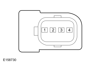 C543, pin 2, component side

 C543, pin 3, component side
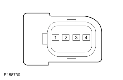 C634, pin 2, component side

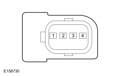 C634, pin 3, component side


 Click here to access the guided procedure (BCM).
 Internet Explorer version 11 or later is required to perform this Pinpoint test.
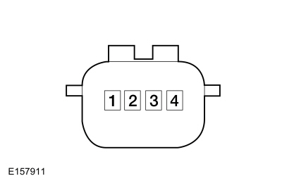 C4817, pin 1, component side

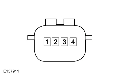 C4817, pin 2, component side


 Click here to access the guided procedure (BCM).
 Internet Explorer version 11 or later is required to perform this Pinpoint test.


 Click here to access the guided procedure (BCM).
 Internet Explorer version 11 or later is required to perform this Pinpoint test.


 Click here to access the guided routine (PCM).
 Internet Explorer version 11 or later is required to perform this Pinpoint test.


 Click here to access the guided procedure (BCM).
 Internet Explorer version 11 or later is required to perform this Pinpoint test.
 Click here to access the guided procedure (BCM).
 Internet Explorer version 11 or later is required to perform this Pinpoint test.
 Click here to access the guided routine (FCIM).
 Internet Explorer version 11 or later is required to perform this Pinpoint test.
 Click here to access the guided routine (PCM).
 Internet Explorer version 11 or later is required to perform this Pinpoint test.
 Click here to access the guided procedure (BCM).
 Internet Explorer version 11 or later is required to perform this Pinpoint test.