Pinpoint Tests
PINPOINT TEST A: THE ENGINE DOES NOT CRANK AND THE RELAY DOES CLICK
| Test Step | Result / Action to Take |
| A1 CHECK THE VOLTAGE TO THE STARTER RELAY | Yes GO to A2 . No REPAIR circuit 1050 (LG/VT) for an open. TEST the system for normal operation. |
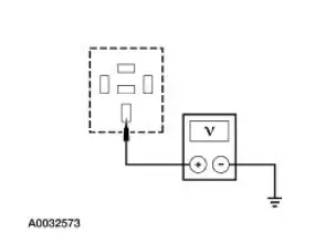
|
|
| A2 CHECK THE VOLTAGE TO THE STARTER MOTOR SOLENOID | Yes GO to A3 . No REPAIR circuit 2037 (RD) for an open. TEST the system for normal operation. |
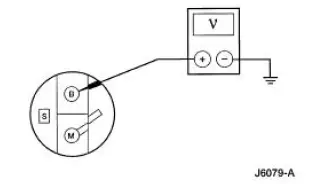
|
|
| A3 MANUALLY JUMP THE STARTER MOTOR | Yes GO to A4 . No INSTALL a new starter motor. REFER to Starter Motor-3.8L or Starter Motor-4.6L . TEST the system for normal operation. |
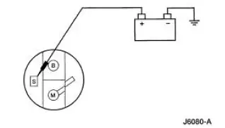
|
|
| A4 TEST THE STARTER MOTOR RELAY | Yes REPAIR circuit 33 (WH/PK)/262 (BN/PK) for an open. TEST the system for normal operation. No INSTALL a new starter motor relay. TEST the system for normal operation. |
|
PINPOINT TEST B: THE ENGINE DOES NOT CRANK AND THE RELAY DOES NOT CLICK
| Test Step | Result / Action to Take |
| B1 CHECK CIRCUIT 33 (WH/PK) FOR VOLTAGE | Yes GO to B10 . No For automatic transmissions, GO to B2 . For manual transmissions, GO to B5 . |
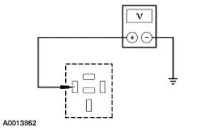
|
|
| B2 CHECK CIRCUIT 32 (RD/LB) FOR VOLTAGE AT THE DIGITAL TR SENSOR | Yes GO to B3 . No GO to B7 . |
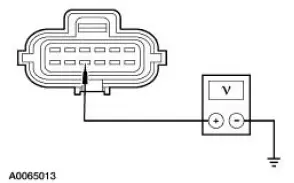
|
|
| B3 CHECK CIRCUIT 33 (WH/PK) FOR OPEN | Yes GO to B4 . No REPAIR circuit 33 (WH/PK). TEST the system for normal operation. |
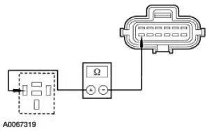
|
|
| B4 CHECK DIGITAL TRANSMISSION RANGE (TR) SENSOR ADJUSTMENT | Yes INSTALL a new digital TR sensor. TEST the system for normal operation. No ADJUST the digital TR as necessary. TEST the system for normal operation. |
|
|
| B5 CHECK CIRCUIT 32 (RD/LB) FOR VOLTAGE AT THE CLUTCH SWITCH OR JUMPER | Yes GO to B6 . No GO to B7 . |
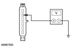
|
|
| B6 CHECK CIRCUIT 33 (WH/PK)/32 (RD/LB) FOR OPEN | Yes INSTALL a new clutch pedal switch. TEST the system for normal operation. No REPAIR circuit 33 (WH/PK)/32 (RD/LB). TEST the system for normal operation. |
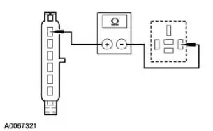
|
|
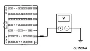
| B7 CHECK FOR VOLTAGE AT FUSE 6 | Yes REPAIR circuit 32 (RD/LB). TEST the system for normal operation. No GO to B8 . |
|
|
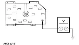
| B8 CHECK CIRCUIT 1050 (LG/VT) FOR VOLTAGE | Yes GO to B9 . No REPAIR circuit 1050 (LG/VT). TEST the system for normal operation. |
|
|
| B9 CHECK THE IGNITION SWITCH | Yes REPAIR circuit 33 (WH/PK). TEST the system for normal operation. No INSTALL a new ignition switch. TEST the system for normal operation. |
|
|
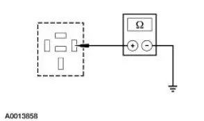
| B10 CHECK CIRCUIT 1205 (BK) FOR OPEN | Yes INSTALL a new starter motor relay. TEST the system for normal operation. No REPAIR circuit 1205 (BK). TEST the system for normal operation. |
|
PINPOINT TEST C: THE ENGINE CRANKS SLOWLY
| Test Step | Result / Action to Take |
| NOTE: Before beginning this test, be sure that the battery is tested and fully charged. | |
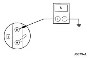
| C1 CHECK THE VOLTAGE TO THE STARTER | Yes GO to C2 . No REPAIR the circuit between the battery and the starter solenoid. CLEAN and TIGHTEN the connections at the battery terminals. TEST the system for normal operation. |
|
|
| C2 CHECK MOTOR GROUND CIRCUIT | Yes INSTALL a new starter motor. REFER to Starter Motor-3.8L or Starter Motor-4.6L . TEST the system for normal operation. No REPAIR the ground circuit as necessary. TEST the system for normal operation. |
|
|
PINPOINT TEST D: UNUSUAL STARTER NOISE
| Test Step | Result / Action to Take |
| D1 CHECK THE STARTER MOTOR MOUNTING | GO to D2 . No REINSTALL the starter motor correctly. REFER to Starter Motor-3.8L or Starter Motor-4.6L in this section. |
|
|
| D2 INSPECT THE STARTER MOTOR | Yes INSTALL a new starter motor. REFER to Starter Motor-3.8L or Starter Motor-4.6L in this section. TEST the system for normal operation. No CHECK the starter drive. REFER to Component Tests, Starter Drive Test in this section. INSTALL a new starter motor. TEST the system for normal operation. |
|
Test yourself
A quick Ford Mustang quiz: every answer comes with an explanation and a link to the manual page.